clutch DODGE TRUCK 1993 Service User Guide
[x] Cancel search | Manufacturer: DODGE, Model Year: 1993, Model line: TRUCK, Model: DODGE TRUCK 1993Pages: 1502, PDF Size: 80.97 MB
Page 158 of 1502
•
REAR
SUSPENSION
AND
AXLE
3 - 31
LUBRICANT
Hypoid gear lubricant, as defined by MIL-L-2105-B
and API GL 5 is the specified lube. MOPAR Hypoid
Gear Lubricant conforms with both of these specifica
tions and is highly recommended.
CAUTION:
If a
rear
axle
is
submerged
in
water,
the
axle
lubricant
must
be
replaced
immediately,
DRAIN
AND
REFILL
(1) Drive the vehicle until the gear lubricant
reaches normal operating temperature. (2) Raise and support the vehicle. (3) Remove the lubricant fill hole plug from the
differential housing cover. (4) Remove the differential housing cover. Allow
the lubricant to completely drain from the housing and axle shaft tubes. (5) Flush the differential and the housing cavity
with a flushing oil to remove residual lubricant and
foreign matter. Do not use water,
steam,
kerosene
or
gasoline for
flushing,
(6) Scrape the residual gasket from the housing
and cover mating surfaces. Clean the mating sur
faces with mineral spirits. Install a new cover gas
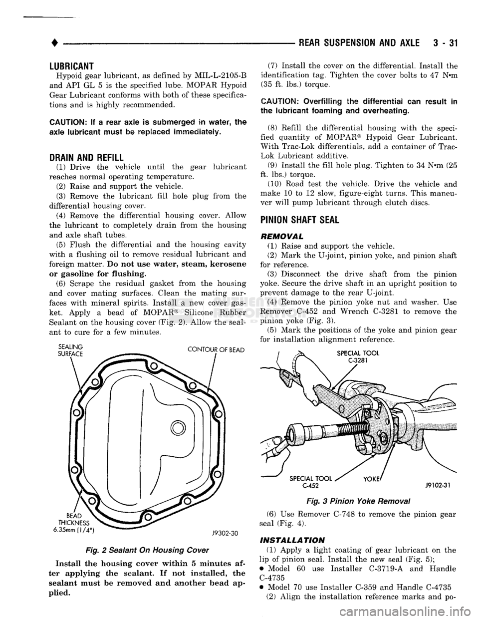
ket. Apply a bead of MOPAR® Silicone Rubber Sealant on the housing cover (Fig. 2). Allow the seal
ant to cure for a few minutes.
SEALING
SURFACE
CONTOUR
OF
BEAD
BEAD
THICKNESS
6.35mm
(1/4")
J9302-30
Fig.
2 Sealant On Housing Cower
Install
the
housing
cover
within 5
minutes
af
ter
applying
the
sealant.
If not
installed,
the
sealant
must be
removed
and another
bead
ap
plied.
(7) Install the cover on the differential. Install the
identification tag. Tighten the cover bolts to 47 Nem (35 ft. lbs.) torque.
CAUTION:
Overfilling
the differential" can
result
in
the
lubricant
foaming
and
overheating.
(8) Refill the differential housing with the speci
fied quantity of MOPAR® Hypoid Gear Lubricant.
With Trac-Lok differentials, add a container of Trac-
Lok Lubricant additive.
(9) Install the fill hole plug. Tighten to 34 N-m (25
ft. lbs.) torque.
(10) Road test the vehicle. Drive the vehicle and
make 10 to 12 slow, figure-eight turns. This maneu
ver will pump lubricant through clutch discs.
PINION
SHAFT
SEAL
REMOVAL
(1) Raise and support the vehicle.
(2) Mark the U-joint, pinion yoke, and pinion shaft
for reference.
(3) Disconnect the drive shaft from the pinion
yoke. Secure the drive shaft in an upright position to
prevent damage to the rear U-joint.
(4) Remove the pinion yoke nut and washer. Use
Remover C-452 and Wrench C-3281 to remove the
pinion yoke (Fig. 3).
(5) Mark the positions of the yoke and pinion gear
for installation alignment reference.
SPECIAL
TOOL
C-3281
SPECIAL
TOOL
C-452
J9102-31
Fig.
3 Pinion Yoke
Removal
(6) Use Remover C-748 to remove the pinion gear
seal (Fig. 4).
INSTALLATION
(1) Apply a light coating of gear lubricant on the
lip of pinion seal. Install the new seal (Fig. 5);
• Model 60 use Installer C-3719-A and Handle C-4735
• Model 70 use Installer C-359 and Handle C-4735 (2) Align the installation reference marks and po-
Page 178 of 1502
REAR
SUSPENSION
AND
AXLE
3 - 51
TRAC-LOK
DIFFERENTIAL
SERVICE
INFORMATION
Model
60 rear
axles equipped
with
Trac-Lok
differ
ential are optionally available for Ram Truck vehi
cles.
DIFFERENTIAL
NOISE
Noise complaints involving Trac-Lok should be
evaluated to determine the source of the noise. If a noise occurs while the vehicle is turning, the proba
ble cause is incorrect or insufficient gear lubricant. Replace the axle gear lubricant and add MOPAR Hy
poid Gear Lubricant Additive. If the chatter persists, clutch disc damage could have occurred.
WARNING: WHEN SERVICING VEHICLES
WITH
A
TRAC-LOK DIFFERENTIAL,
DO NOT
USE
THE EN
GINE
TO
ROTATE
THE
AXLE
AND
WHEELS.
BOTH
REAR
WHEELS MUST
BE
RAISED, FROM
THE
SUR
FACE
AND THE
VEHICLE SUPPORTED. TRAC-LOK
CAN EXERT ENOUGH DRIVING FORCE
TO
CAUSE
THE VEHICLE
TO
MOVE.
(4) Place a block of wood that is 2 inches high and
a minimum of 3 inches wide in front of one of the
front tires.
(5) With a gradual throttle opening, attempt to
slowly drive the vehicle over the block of wood.
(6) If the Kraft paper slips out before the front
wheel moves over the block of wood; reposition the vehicle so paper and board are under the opposite
rear wheel. Attempt to drive over the block of wood
the second time.
(7) If the front wheel moves over the block of wood,
the axle can be considered to be functioning nor mally.
LUBRICANTS
The lubricant recommended for Trac-Lok differen
tial is API grade GL 5. A container of Trac-Lok Lu
bricant (friction modifier) should be added after service. Refer to Group 0, Lubrication and Maintenance for
additional information.
DIFFERENTIAL
TEST
(1) Drive the vehicle to thoroughly warm up the
lubricant in the rear axle. (2) Place a large piece of Kraft paper over a
smooth Formica board.
(3) Drive the vehicle over the Formica board until
one rear wheel/tire is in the center of the board and
paper.
COMPONENTS
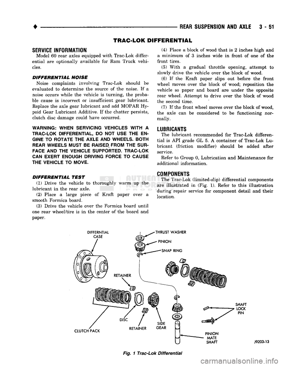
The Trac-Lok (limited-slip) differential components
are illustrated in (Fig. 1). Refer to this illustration
during repair service for component detail and their
location.
DIFFERNTIAL
CASE
THRUST
WASHER
PINION
SNAP
RING
SHAFT
LOCK
PIN
CLUTCH PACK
PINION
MATE
SHAFT
J9203-13
Fig.
1
Trac-Lok
Differential
Page 180 of 1502
•
REAR SUSPENSION
AND
AXLE
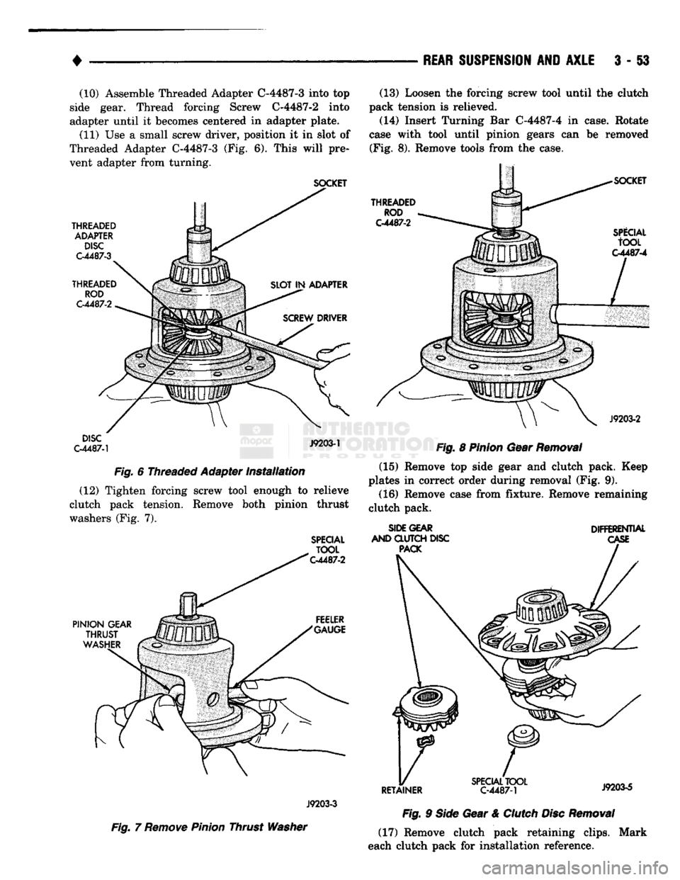
3 - §3 (10) Assemble Threaded Adapter C-4487-3 into top
side gear. Thread forcing Screw C-4487-2 into
adapter until it becomes centered in adapter plate.
(11) Use a small screw driver, position it in slot of
Threaded Adapter C-4487-3 (Fig. 6). This will pre
vent adapter from turning.
SOCKET
THREADED ADAPTER DISC
C-4487-3
THREADED ROD
C-4487-2
DISC
C-4487-1
J9203-1
Fig. 6 Threaded Adapter Installation (12) Tighten forcing screw tool enough to relieve
clutch pack tension. Remove both pinion thrust
washers (Fig. 7).
SPECIAL
TOOL
C-4487-2
(13) Loosen the forcing screw tool until the clutch
pack tension is relieved.
(14) Insert Turning Bar C-4487-4 in case. Rotate
case with tool until pinion gears can be removed (Fig. 8). Remove tools from the case.
THREADED
ROD
C-4487-2
SPlCIAL
tOOL
C-4487-4
J9203-2
Fig. 8 Pinion Gear Removal (15) Remove top side gear and clutch pack. Keep
plates in correct order during removal (Fig. 9).
(16) Remove case from fixture. Remove remaining
clutch pack.
SIDE GEAR
AND CLUTCH DISC PACK DIFFERENTIAL
CASE
PINION
GEAR
THRUST
WASHER FEELER
"GAUGE
33
X
/
J9203-3
Fig. 7 Remove Pinion Thrust Washer
RETAINER
SPECIAL
TOOL
C-4487-1 J9203-5
Fig. 9 Side Gear & Clutch Disc Removal (17) Remove clutch pack retaining clips. Mark
each clutch pack for installation reference.
Page 181 of 1502
3
- 54
REAR SUSPENSION
AID
AXLE
•
CLEANING AND INSPECTION
(1) Clean all components in cleaning solvent. Dry
components with compressed air. (2) Inspect clutch pack plates for wear, scoring or
damage. Replace both clutch packs if any one compo
nent in either pack is damaged. (3) Inspect side and pinion gears. Replace any gear
that is worn, cracked, chipped or damaged. (4) Inspect differential case and pinion shaft. Re
place if worn or damaged.
ASSEMBLY
(1) The clutch discs are replaceable as complete
sets only. If one clutch disc pack is damaged,
both packs must be replaced. Lubricate each com
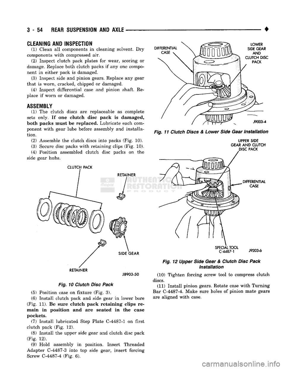
ponent with gear lube before assembly and installa tion. (2) Assemble the clutch discs into packs (Fig. 10).
(3) Secure disc packs with retaining clips (Fig. 10).
(4) Position assembled clutch disc packs on the
side gear hubs.
CLUTCH
PACK
RETAINER
J8903-50
Fig.
10
Clutch
Disc
Pack
(5) Position case on fixture (Fig. 3).
(6) Install clutch pack and side gear in lower bore
(Fig. 11). Be sure clutch pack retaining clips re
main in position and are seated in the case
pockets.
(7) Install lubricated Step Plate C-4487-1 on first
clutch pack (Fig. 12). (8) Install the upper side gear and clutch disc pack
(Fig. 12).
(9) Hold assembly in position. Insert Threaded
Adapter C-4487-3 into top side gear, insert forcing Screw C-4487-4 (Fig. 6).
Fig.
11
Clutch
Discs
&
Lower
Side
Gear
Installation
UPPER SIDE
GEAR AND
CLUTCH
DISC PACK
Installation
(10) Tighten forcing screw tool to compress clutch
discs.
(11) Install pinion gears. Rotate case with Turning
Bar C-4487-4. Make sure holes of pinion mate gears are aligned with case.
Page 182 of 1502
•
REAR
SUSPENSION
AND
AXLE
3 - 55
(12) Tighten forcing screw
to
compress
the
conned
plates.
Lubricate
and
install pinion gear thrust washers with
a
small screw driver.
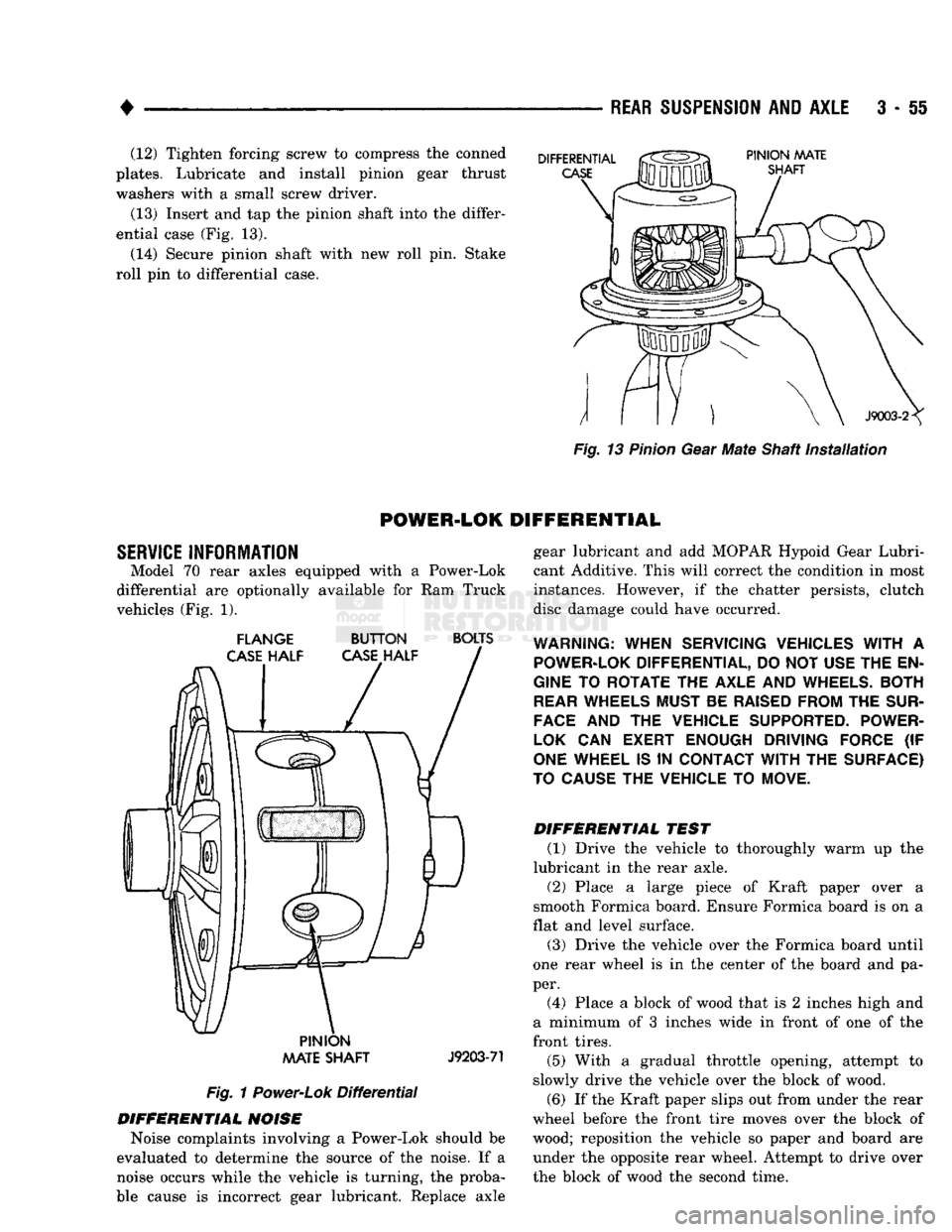
(13) Insert and tap
the
pinion shaft into the differ
ential case (Fig.
13).
(14) Secure pinion shaft with
new
roll pin. Stake
roll
pin
to
differential case.
Fig.
13
Pinion
Gear
Mate
Shaft
installation
POWER-LOK
DIFFERENTIAL
SERVICE
INFORMATION Model
70
rear axles equipped with
a
Power-Lok
differential
are
optionally available
for
Ram
Truck
vehicles (Fig.
1).
FLANGE
BUTTON
BOLTS
PINION
AAATE
SHAFT
J9203-71
Fig.
1
Power-Lok
Differential
DIFFERENTIAL
NOISE
Noise complaints involving
a
Power-Lok should
be
evaluated
to
determine
the
source
of
the noise.
If a
noise occurs while
the
vehicle
is
turning,
the
proba
ble cause
is
incorrect gear lubricant. Replace axle gear lubricant
and add
MOPAR Hypoid Gear Lubri
cant Additive. This will correct the condition
in
most
instances. However,
if the
chatter persists, clutch
disc damage could have occurred.
WARNING:
WHEN SERVICING VEHICLES
WITH
A
POWER-LOK
DIFFERENTIAL, DO NOT USE THE EN
GINE
TO
ROTATE THE AXLE AND
WHEELS.
BOTH
REAR
WHEELS MUST BE
RAISED
FROM THE
SUR
FACE
AND
THE
VEHICLE SUPPORTED. POWER-
LOK
CAN
EXERT ENOUGH DRIVING FORCE
(IF
ONE
WHEEL IS
IN
CONTACT
WITH
THE SURFACE)
TO
CAUSE
THE VEHICLE TO MOVE.
DIFFERENTIAL
TEST
(1) Drive
the
vehicle
to
thoroughly warm
up the
lubricant
in
the
rear axle.
(2) Place
a
large piece
of
Kraft paper over
a
smooth Formica board. Ensure Formica board
is on a
flat and level surface.
(3) Drive
the
vehicle over
the
Formica board until
one rear wheel
is in the
center
of
the board
and
pa
per. (4) Place
a
block
of
wood that
is 2
inches high
and
a minimum
of 3
inches wide
in
front
of
one
of
the
front tires.
(5) With
a
gradual throttle opening, attempt
to
slowly drive
the
vehicle over
the
block
of
wood.
(6)
If
the Kraft paper slips out from under the rear
wheel before
the
front tire moves over
the
block
of
wood; reposition
the
vehicle
so
paper
and
board
are
under
the
opposite rear wheel. Attempt
to
drive over
the block
of
wood
the
second time.
Page 183 of 1502
3
- 56
REAR SUSPENSION
AND
AXLE
CLUTCH
PLATES
J9203-72
BUTTON
HALF
FLANGE
HALF
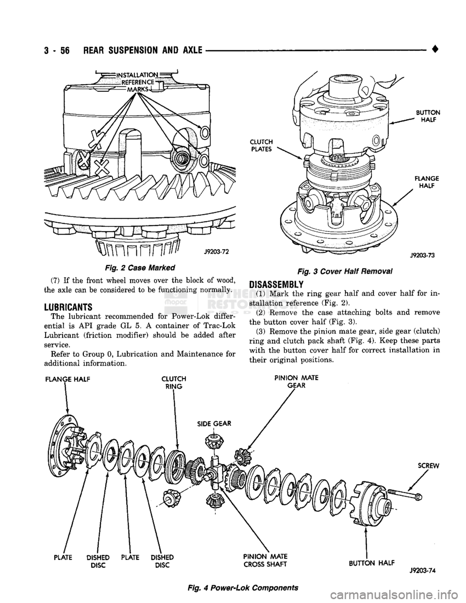
Fig.
2
Case
Marked
(7)
If the front wheel moves over the block of wood,
the axle can be considered to be functioning normally.
LUBRICANTS
The lubricant recommended for Power-Lok differ
ential is API grade GL 5. A container of Trac-Lok
Lubricant (friction modifier) should be added after
service. Refer to Group 0, Lubrication and Maintenance for
additional information.
FLANGE
HALF
CLUTCH
RING
J9203-73
Fig.
3
Cover
Half
Removal
DISASSEMBLY
(1) Mark the ring gear half and cover half for in
stallation reference (Fig. 2). (2) Remove the case attaching bolts and remove
the button cover half (Fig. 3). (3) Remove the pinion mate gear, side gear (clutch)
ring and clutch pack shaft (Fig. 4). Keep these parts with the button cover half for correct installation in
their original positions.
PINION MATE
GEAR
SCREW
PLATE
DISHED
DISC
PLATE
DISHED
DISC PINION AAATE
CROSS
SHAFT
BUTTON HALF
J9203-74
Fig.
4
Power-Lok
Components
Page 184 of 1502
•
REAR SUSPENSION
AND
AXLE
3 - 57 (4) Remove the same parts listed above from the
ring gear flange half of the case. (Fig. 4). Keep these
parts with the flange cover half for correct installa tion in their original positions.
CLEANING AND INSPECTION
(1) Clean all components (Fig. 4) in cleaning sol
vent. Dry components with compressed air. (2) Inspect clutch pack plates for wear, scoring or
damage. Replace both clutch packs if any one compo
nent in either pack is damaged. (3) Inspect side and pinion gears. Replace any gear
that is worn, cracked, chipped or damaged. (4) Inspect differential case and pinion shaft. Re
place if worn or damaged.
ASSEMBLY
(1) The clutch discs are replaceable as complete
sets only. If one clutch disc pack is damaged,
both packs must be replaced. Lubricate each com
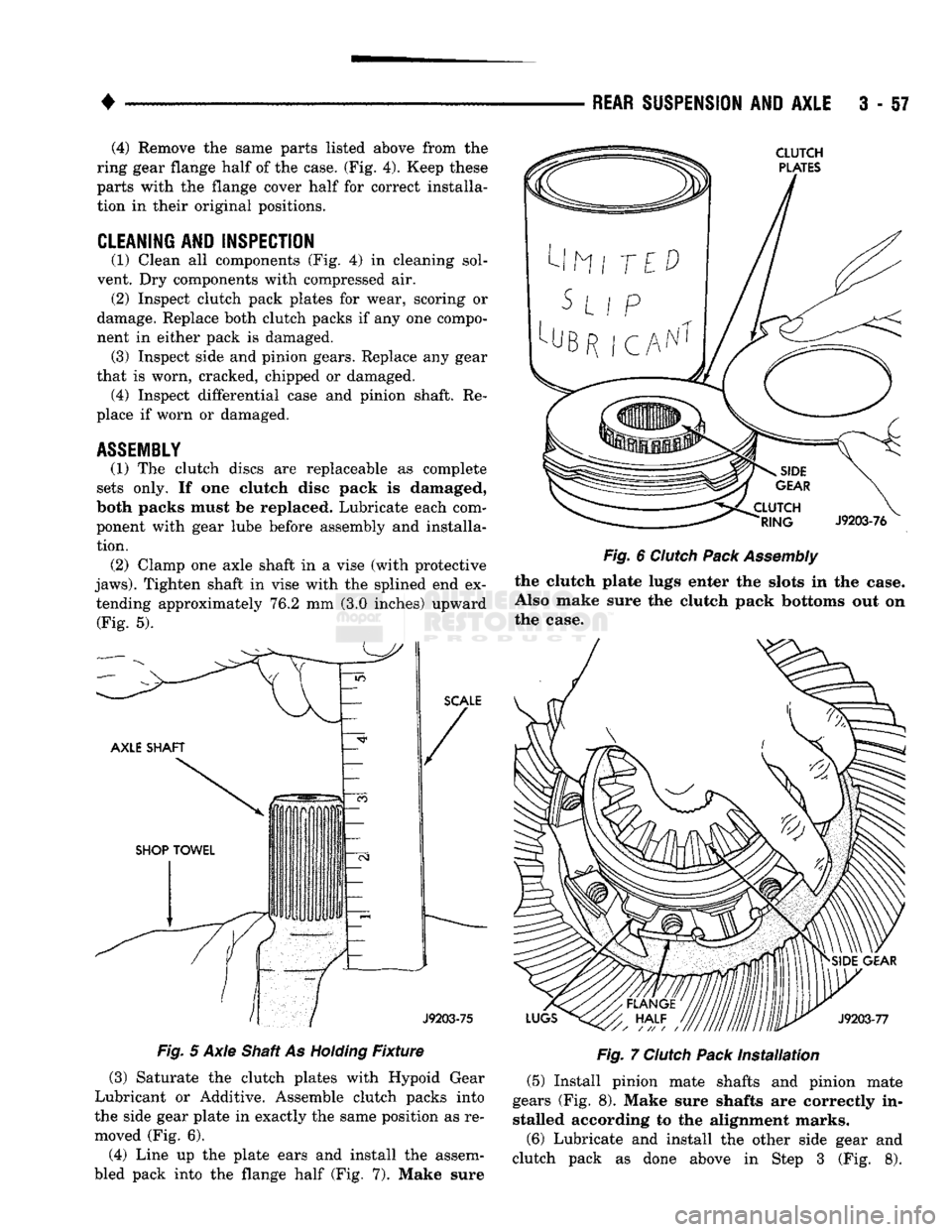
ponent with gear lube before assembly and installa tion. (2) Clamp one axle shaft in a vise (with protective
jaws).
Tighten shaft in vise with the splined end ex tending approximately 76.2 mm (3.0 inches) upward (Fig. 5).
Fig.
5 Axle Shaft As
Holding
Fixture
(3) Saturate the clutch plates with Hypoid Gear
Lubricant or Additive. Assemble clutch packs into
the side gear plate in exactly the same position as re moved (Fig. 6).
(4) Line up the plate ears and install the assem
bled pack into the flange half (Fig. 7). Make sure
Fig.
6
Clutch
Pack
Assembly
the clutch plate lugs enter the slots in the case.
Also make sure the clutch pack bottoms out on
the case.
Fig.
7
Clutch
Pack
Installation
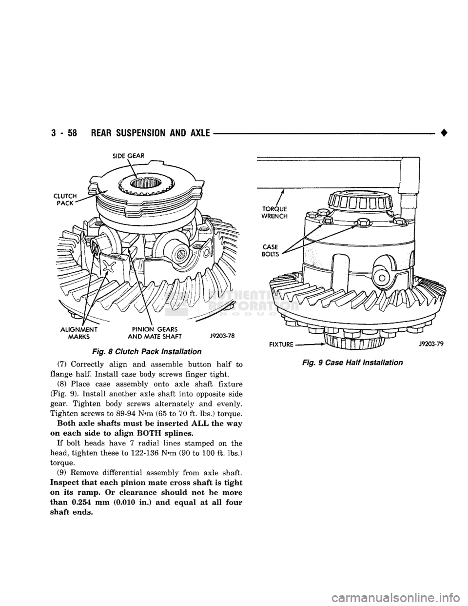
(5) Install pinion mate shafts and pinion mate
gears (Fig. 8). Make sure shafts are correctly in stalled according to the alignment marks.
(6) Lubricate and install the other side gear and
clutch pack as done above in Step 3 (Fig. 8).
Page 185 of 1502
3
- 58
REAR SUSPENSION
AND
AXLE
•
SIDE
GEAR
ALIGNMENT PINION
GEARS MARKS
AND
MATE SHAFT
J9203-78
Fig.
8
Clutch
Pack
Installation
(7) Correctly align and assemble button half to
flange
half.
Install case body screws finger tight.
(8) Place case assembly onto axle shaft fixture
(Fig. 9). Install another axle shaft into opposite side
gear. Tighten body screws alternately and evenly.
Tighten screws to 89-94 N«m (65 to 70 ft. lbs.) torque.
Both axle shafts must be inserted ALL the way
on each side to align BOTH splines.
If bolt heads have 7 radial lines stamped on the
head, tighten these to 122-136 N-m (90 to 100 ft. lbs.)
torque.
(9) Remove differential assembly from axle shaft.
Inspect that each pinion mate cross shaft is tight
on its ramp. Or clearance should not be more
than 0.254 mm (0.010 in.) and equal at all four shaft ends.
Fig.
9
Case
Half
Installation
Page 254 of 1502
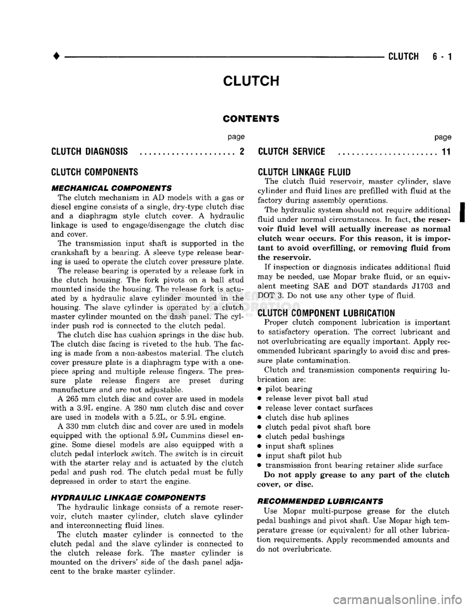
CLUTCH
6 - 1
CLUTCH
CONTENTS
page
CLUTCH
DIAGNOSIS
2
CLUTCH
COMPONENTS
MECHANICAL COMPONENTS
The clutch mechanism
in
AD
models with
a gas or
diesel engine consists
of a
single, dry-type clutch disc and
a
diaphragm style clutch cover.
A
hydraulic
linkage
is
used
to
engage/disengage
the
clutch disc
and cover.
The transmission input shaft
is
supported
in the
crankshaft
by a
bearing.
A
sleeve type release bear
ing
is
used
to
operate
the
clutch cover pressure plate.
The release bearing
is
operated
by a
release fork
in
the clutch housing.
The
fork pivots
on a
ball stud
mounted inside
the
housing.
The
release fork
is
actu ated
by a
hydraulic slave cylinder mounted
in the
housing.
The
slave cylinder
is
operated
by a
clutch master cylinder mounted
on the
dash panel.
The
cyl
inder push
rod is
connected
to the
clutch pedal.
The clutch disc
has
cushion springs
in the
disc
hub.
The clutch disc facing
is
riveted
to the hub. The
fac ing
is
made from
a
non-asbestos material.
The
clutch
cover pressure plate
is a
diaphragm type with
a one-
piece spring
and
multiple release fingers.
The
pres sure plate release fingers
are
preset during
manufacture
and are not
adjustable.
A
265 mm
clutch disc
and
cover
are
used
in
models
with
a 3.9L
engine.
A 280 mm
clutch disc
and
cover are used
in
models with
a 5.2L, or
5.9L engine.
A
330 mm
clutch disc
and
cover
are
used
in
models
equipped with
the
optional
5.9L
Cummins diesel
en
gine.
Some diesel models
are
also equipped with
a
clutch pedal interlock switch.
The
switch
is in
circuit
with
the
starter relay
and is
actuated
by the
clutch
pedal
and
push
rod. The
clutch pedal must
be
fully depressed
in
order
to
start
the
engine.
HYDRAULIC LINKAGE COMPONENTS
The hydraulic linkage consists
of a
remote reser
voir, clutch master cylinder, clutch slave cylinder and interconnecting fluid lines.
The clutch master cylinder
is
connected
to the
clutch pedal
and the
slave cylinder
is
connected
to
the clutch release fork.
The
master cylinder
is
mounted
on the
drivers' side
of the
dash panel adja
cent
to the
brake master cylinder.
page
CLUTCH
SERVICE
11
CLUTCH LINKAGE FLUID
The clutch fluid reservoir, master cylinder, slave
cylinder
and
fluid lines
are
prefilled with fluid
at the
factory during assembly operations. The hydraulic system should
not
require additional
fluid under normal circumstances.
In
fact,
the
reser
voir fluid level will actually increase
as
normal clutch wear occurs.
For
this reason,
it is
impor
tant
to
avoid overfilling,
or
removing fluid from
the reservoir. If inspection
or
diagnosis indicates additional fluid
may
be
needed,
use
Mopar brake fluid,
or an
equiv
alent meeting
SAE and DOT
standards J1703
and
DOT
3. Do not use any
other type
of
fluid.
CLUTCH
COMPONENT LUBRICATION
Proper clutch component lubrication
is
important
to satisfactory operation.
The
correct lubricant
and
not overlubricating
are
equally important. Apply rec
ommended lubricant sparingly
to
avoid disc
and
pres sure plate contamination. Clutch
and
transmission components requiring
lu
brication
are:
• pilot bearing
• release lever pivot ball stud
• release lever contact surfaces
• clutch disc
hub
splines
• clutch pedal pivot shaft bore
• clutch pedal bushings
• input shaft splines
• input shaft pilot
hub
• transmission front bearing retainer slide surface Do
not
apply grease
to any
part
of the
clutch
cover,
or
disc.
RECOMMENDED LUBRICANTS
Use Mopar multi-purpose grease
for the
clutch
pedal bushings
and
pivot shaft.
Use
Mopar high tem
perature grease
(or
equivalent)
for all
other lubrica
tion requirements. Apply recommended amounts
and
do
not
over lubricate.
Page 255 of 1502
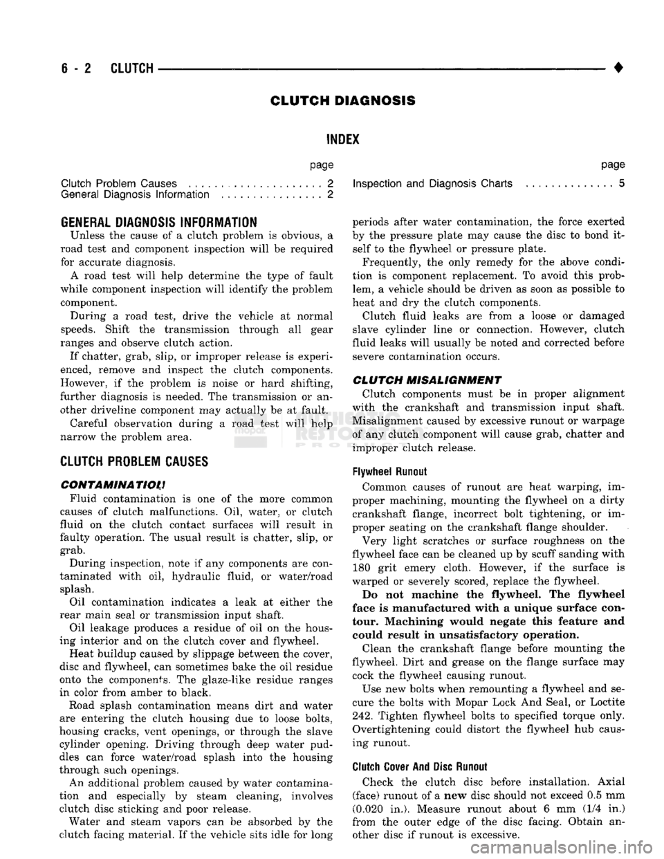
6
- 2
CLUTCH
•
CLUTCH DIAGNOSIS
INDEX
page
Clutch Problem
Causes
, 2
General
Diagnosis
Information
2
GENERAL
DIAGNOSIS INFORMATION
Unless the cause of a clutch problem is obvious, a
road test and component inspection will be required
for accurate diagnosis. A road test will help determine the type of fault
while component inspection will identify the problem component. During a road test, drive the vehicle at normal
speeds. Shift the transmission through all gear
ranges and observe clutch action. If chatter, grab, slip, or improper release is experi
enced, remove and inspect the clutch components.
However, if the problem is noise or hard shifting,
further diagnosis is needed. The transmission or an
other driveline component may actually be at fault. Careful observation during a road test will help
narrow the problem area.
CLUTCH PROBLEM
CAUSES
CONTAMINATION Fluid contamination is one of the more common
causes of clutch malfunctions. Oil, water, or clutch
fluid on the clutch contact surfaces will result in
faulty operation. The usual result is chatter, slip, or
grab.
During inspection, note if any components are con
taminated with oil, hydraulic fluid, or water/road splash.
Oil contamination indicates a leak at either the
rear main seal or transmission input shaft.
Oil leakage produces a residue of oil on the hous
ing interior and on the clutch cover and flywheel.
Heat buildup caused by slippage between the cover,
disc and flywheel, can sometimes bake the oil residue
onto the components. The glaze-like residue ranges
in color from amber to black.
Road splash contamination means dirt and water
are entering the clutch housing due to loose bolts,
housing cracks, vent openings, or through the slave
cylinder opening. Driving through deep water pud
dles can force water/road splash into the housing
through such openings.
An additional problem caused by water contamina
tion and especially by steam cleaning, involves
clutch disc sticking and poor release. Water and steam vapors can be absorbed by the
clutch facing material. If the vehicle sits idle for long
page
Inspection
and
Diagnosis
Charts 5
periods after water contamination, the force exerted
by the pressure plate may cause the disc to bond it self to the flywheel or pressure plate.
Frequently, the only remedy for the above condi
tion is component replacement. To avoid this prob
lem, a vehicle should be driven as soon as possible to
heat and dry the clutch components.
Clutch fluid leaks are from a loose or damaged
slave cylinder line or connection. However, clutch
fluid leaks will usually be noted and corrected before severe contamination occurs.
CLUTCH MISALIGNMENT
Clutch components must be in proper alignment
with the crankshaft and transmission input shaft.
Misalignment caused by excessive runout or warpage of any clutch component will cause grab, chatter and improper clutch release.
Flywheel
Runout
Common causes of runout are heat warping, im
proper machining, mounting the flywheel on a dirty crankshaft flange, incorrect bolt tightening, or im
proper seating on the crankshaft flange shoulder.
Very light scratches or surface roughness on the
flywheel face can be cleaned up by scuff sanding with 180 grit emery cloth. However, if the surface is
warped or severely scored, replace the flywheel.
Do not machine the flywheel. The flywheel
face is manufactured with a unique surface con
tour. Machining would negate this feature and could result in unsatisfactory operation.
Clean the crankshaft flange before mounting the
flywheel. Dirt and grease on the flange surface may cock the flywheel causing runout.
Use new bolts when remounting a flywheel and se
cure the bolts with Mopar Lock And Seal, or Loctite
242.
Tighten flywheel bolts to specified torque only.
Overtightening could distort the flywheel hub caus
ing runout.
Clutch
Cover
And Disc
Runout
Check the clutch disc before installation. Axial
(face) runout of a new disc should not exceed 0.5 mm
(0.020 in.). Measure runout about 6 mm (1/4 in.)
from the outer edge of the disc facing. Obtain an other disc if runout is excessive.