gas tank size DODGE TRUCK 1993 Service Repair Manual
[x] Cancel search | Manufacturer: DODGE, Model Year: 1993, Model line: TRUCK, Model: DODGE TRUCK 1993Pages: 1502, PDF Size: 80.97 MB
Page 719 of 1502

9
- 114 5.9L
(DIESEL) ENGINE
—
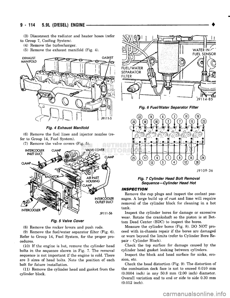
Fig.
4
Exhaust
Manifold
(6) Remove the fuel lines and injector nozzles (re
fer to Group 14, Fuel System).
(7) Remove the valve covers (Fig. 5).
Fig.
5
Valve
Cover
(8) Remove the rocker levers and push rods.
(9) Remove the fuel/water separator filter (Fig. 6).
Refer to Group 14, Fuel System, for the proper pro
cedures.
(10) If the engine is hot, remove the cylinder head
bolts in the sequence shown in Fig. 7..The removal sequence is not important if the engine is cold. There
are 3 sizes of head bolts. Note the position of each
bolt for future installation.
(11) Remove the cylinder head and gasket from the
cylinder block.
•
Fig. 6 Fuel/Water Separator Filter J9109-36
Fig. 7 Cylinder Head Bolt Removal Sequence—Cylinder Head Hot
INSPECTION
Remove the cup plugs and inspect the coolant pas
sages.
A large build up of rust and lime will require
removal of the cylinder block for cleaning in a hot
tank.
Inspect the cylinder bores for damage or excessive
wear. Rotate the crankshaft so the piston is at Bot
tom Dead Center (BDC) to inspect the bores. Measure the cylinder bores (Fig. 8). DO NOT pro
ceed with in-chassis repair if the bores are damaged
or worn beyond the limits (refer to Cylinder Bore Re
pair - Cylinder Block).
Check the top surface for damage caused by the
cylinder head gasket leaking between cylinders.
Inspect the block and head surface for nicks, ero
sion, etc. Check the head distortion (Fig. 9). The distortion of
the combustion deck face is not to exceed 0.010 mm (0.0004 inch) in any 50.8 mm (2.00 inch) diameter.
Overall variation end to end or side to side 0.30 mm (0.012 inch).
(3) Disconnect the radiator and heater hoses (refer
to Group 7, Cooling System). (4) Remove the turbocharger.
(5) Remove the exhaust manifold (Fig. 4).
Page 1159 of 1502

21 - 158
TRANSMISSION
OVERHAUL—32RH
•
OVERHAUL SERVICE
INFORMATION
Inspect all the transmission bushings during over
haul. Bushing condition is important as worn, scored
bushings contribute to low pressures, clutch slip and accelerated wear of other components. Do not replace
bushings as a matter of course. Replace bushings
only when actually worn or scored. Use recommended tools to replace bushings. The
tools are sized and designed to remove, install and seat bushings correctly, The bushing replacement
tools are included in Bushing Tool Set C-3887-B. The
tool set is manufactured by the Miller Tool Co. and is available through the dealer tool program. Pre-sized service bushings are available for re
placement purposes. Only the sun gear bushings are
not serviced. Low cost of the sun gear assembly
makes it easier to simply replace the gear and bush
ings as an assembly. Heli-Coil inserts are recommended for repairing
damaged, stripped or worn threads in aluminum
parts.
These inserts are available from most automo
tive jobbers. Stainless steel inserts are preferred. The use of crocus cloth is permissible where neces
sary, providing it is used carefully. When used on
valves, use extreme care to avoid rounding off sharp
edges.
Sharp edges are vital as they prevent foreign
matter from getting between the valve and valve
bore.
Do not reuse oil seals, gaskets, seal rings, or
O-rings during overhaul. Replace these parts as a
matter of course. Also do not reuse snap rings or
E-clips that are bent or distorted. Replace these parts as well.
Lubricate transmission parts with Mopar ATF
Plus,
Type 7176, or Dexron II™ transmission fluid during overhaul and assembly.
Use Ru-Glyde or Door Eze to lubricate clutch pis
ton seals. Use petroleum jelly to lubricate O-rings and thrust washers. Petroleum jelly can also be used
to hold parts in place during reassembly.
TRANSMISSION
CASE
CLEAN1N8
AND
INSPECTION
Clean the case in a solvent tank. Flush the case
bores and fluid passages thoroughly with solvent. Dry the case and all fluid passages with compressed
air. Be sure all solvent is removed from the case and
that all fluid passages are clear. Do not use shop towels or rags to dry the case
(or any other transmission component) unless
they are made from lint-free materials. Lint will
readily adhere to case surfaces and transmission
components and will circulate throughout the
transmission after assembly. A sufficient quan
tity of lint can block fluid passages and interfere
with valve body operation. Inspect the case for cracks, porous spots, worn
bores,
or damaged threads. Damaged threads can be repaired with Helicoil thread inserts. However, the
case will have to be replaced if it exhibits any type of
damage or wear.
Lubricate the front band adjusting screw threads
with petroleum jelly and thread the screw part-way into the case. Be sure the screw turns freely.
Remount the case in Repair Stand C-3750-B after
cleaning and inspection.
OVERRUNNING CLUTCH-LOW-REVERSE
DRUM-REAR
SUPPORT OVERHAUL
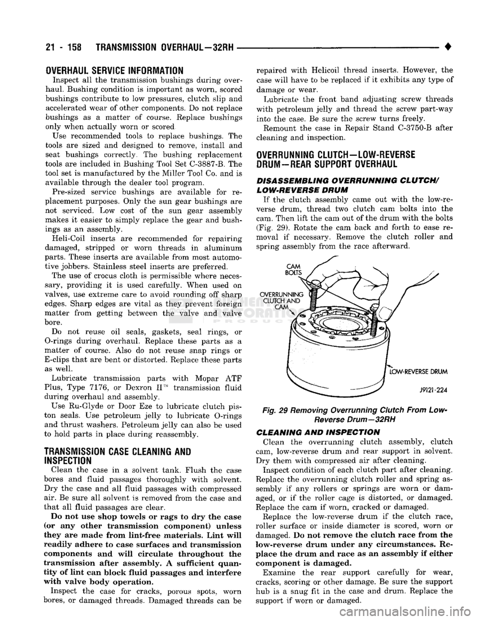
DISASSEMBLING OVERRUNNING CLUTCH/ LOW-REVERSE DRUM
If the clutch assembly came out with the low-re
verse drum, thread two clutch cam bolts into the cam. Then lift the cam out of the drum with the bolts (Fig. 29). Rotate the cam back and forth to ease re
moval if necessary. Remove the clutch roller and spring assembly from the race afterward.
Fig, 29 Removing Overrunning Clutch From Low- Reverse Drum—32RH
CLEANING AND INSPECTION Clean the overrunning clutch assembly, clutch
cam, low-reverse drum and rear support in solvent.
Dry them with compressed air after cleaning. Inspect condition of each clutch part after cleaning.
Replace the overrunning clutch roller and spring as sembly if any rollers or springs are worn or dam
aged, or if the roller cage is distorted, or damaged.
Replace the cam if worn, cracked or damaged.
Replace the low-reverse drum if the clutch race,
roller surface or inside diameter is scored, worn or damaged. Do not remove the clutch race from the
low-reverse drum under any circumstances. Re place the drum and race as an assembly if either component is damaged.
Examine the rear support carefully for wear,
cracks, scoring or other damage. Be sure the support
hub is a snug fit in the case and drum. Replace the support if worn or damaged.
Page 1203 of 1502

21
- 202
TRANSMISSION
OVERHAUL—36RH/37RH
•
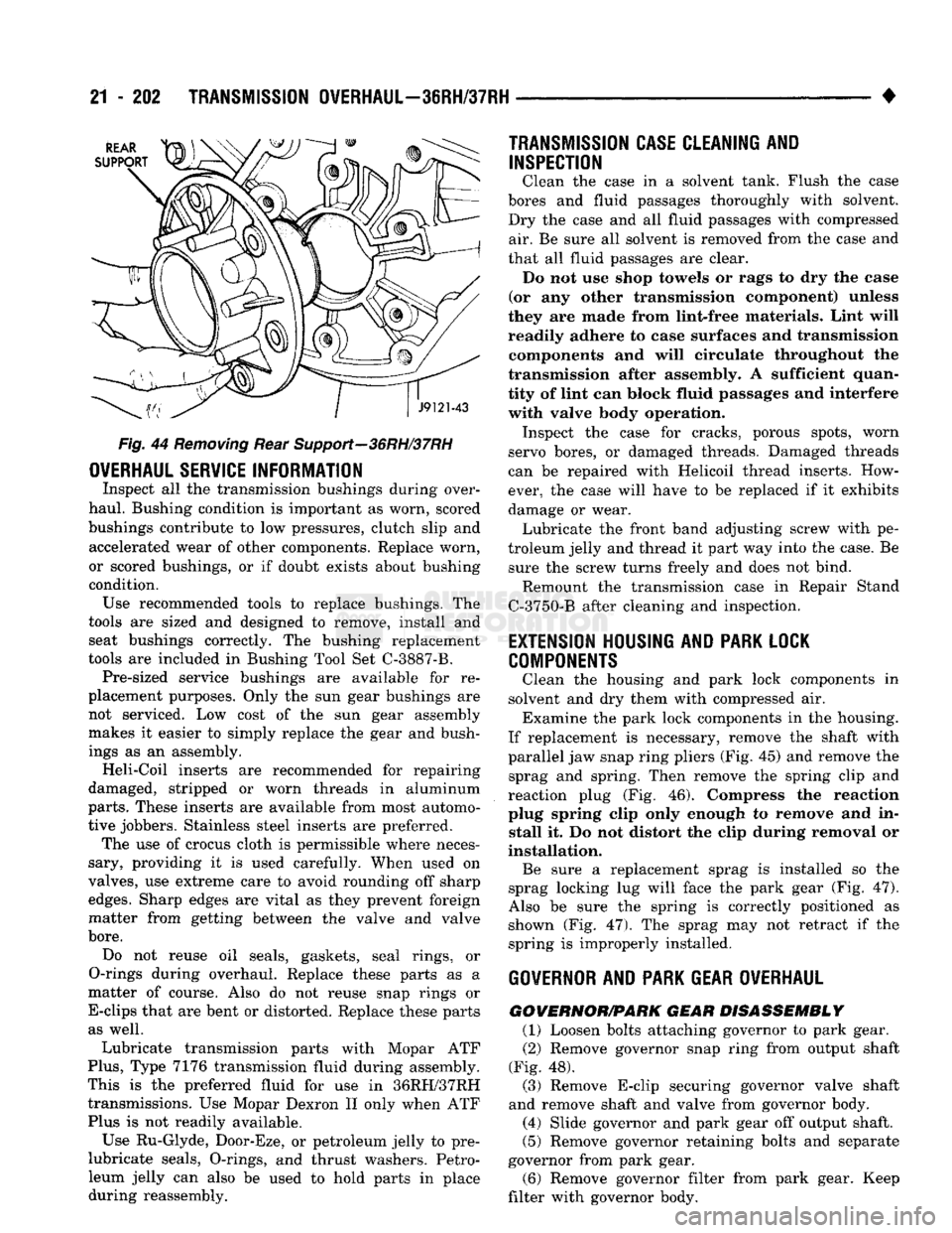
Fig.
44
Removing
Rear Support—36RH/37RH
OVERHAUL
SERVICE
INFORMATION
Inspect
all the
transmission bushings during over
haul. Bushing condition
is
important
as
worn, scored
bushings contribute
to low
pressures, clutch slip
and
accelerated wear
of
other components. Replace worn,
or scored bushings,
or if
doubt exists about bushing
condition. Use recommended tools
to
replace bushings.
The
tools
are
sized
and
designed
to
remove, install
and
seat bushings correctly.
The
bushing replacement
tools
are
included
in
Bushing Tool
Set
C-3887-B. Pre-sized service bushings
are
available
for re
placement purposes. Only
the sun
gear bushings
are
not serviced.
Low
cost
of the sun
gear assembly
makes
it
easier
to
simply replace
the
gear
and
bush
ings
as an
assembly. Heli-Coil inserts
are
recommended
for
repairing
damaged, stripped
or
worn threads
in
aluminum
parts.
These inserts
are
available from most automo
tive jobbers. Stainless steel inserts
are
preferred. The
use of
crocus cloth
is
permissible where neces
sary, providing
it is
used carefully. When used
on
valves,
use
extreme care
to
avoid rounding
off
sharp
edges.
Sharp edges
are
vital
as
they prevent foreign
matter from getting between
the
valve
and
valve
bore.
Do
not
reuse
oil
seals, gaskets, seal rings,
or
O-rings during overhaul. Replace these parts
as a
matter
of
course. Also
do not
reuse snap rings
or
E-clips that
are
bent
or
distorted. Replace these parts as well.
Lubricate transmission parts with Mopar
ATF
Plus,
Type
7176
transmission fluid during assembly.
This
is the
preferred fluid
for use in
36RH/37RH transmissions.
Use
Mopar Dexron
II
only when
ATF
Plus
is not
readily available.
Use Ru-Glyde, Door-Eze,
or
petroleum jelly
to pre-
lubricate seals, O-rings,
and
thrust washers. Petro
leum jelly
can
also
be
used
to
hold parts
in
place during reassembly.
TRANSMISSION CASE
CLEAN1NI
AND
INSPECTION
Clean
the
case
in a
solvent tank. Flush
the
case
bores
and
fluid passages thoroughly with solvent.
Dry
the
case
and all
fluid passages with compressed air.
Be
sure
all
solvent
is
removed from
the
case
and
that
all
fluid passages
are
clear. Do
not use
shop towels
or
rags
to dry the
ease
(or
any
other transmission component) unless
they
are
made from lint-free materials. Lint will
readily adhere
to
case surfaces
and
transmission components
and
will circulate throughout
the
transmission after assembly.
A
sufficient quan
tity
of
lint
can
block fluid passages
and
interfere with valve body operation. Inspect
the
case
for
cracks, porous spots, worn
servo bores,
or
damaged threads. Damaged threads
can
be
repaired with Helicoil thread inserts. How
ever,
the
case will have
to be
replaced
if it
exhibits
damage
or
wear. Lubricate
the
front band adjusting screw with
pe
troleum jelly
and
thread
it
part
way
into
the
case.
Be
sure
the
screw turns freely
and
does
not
bind. Remount
the
transmission case
in
Repair Stand
C-3750-B after cleaning
and
inspection.
EXTENSION
HOUSING
AND PARK
LOCK
COMPONENTS
Clean
the
housing
and
park lock components
in
solvent
and dry
them with compressed
air.
Examine
the
park lock components
in the
housing.
If replacement
is
necessary, remove
the
shaft with
parallel
jaw
snap ring pliers
(Fig. 45) and
remove
the
sprag
and
spring. Then remove
the
spring clip
and
reaction plug
(Fig. 46).
Compress
the
reaction
plug spring clip only enough
to
remove
and in
stall
it. Do not
distort
the
clip during removal
or
installation. Be sure
a
replacement sprag
is
installed
so the
sprag locking
lug
will face
the
park gear
(Fig. 47).
Also
be
sure
the
spring
is
correctly positioned
as
shown
(Fig. 47). The
sprag
may not
retract
if the
spring
is
improperly installed.
GOVERNOR
AND PARK
GEAR OVERHAUL
GOWERNOR/PARK
GEAR DISASSEMBLY
(1) Loosen bolts attaching governor
to
park gear.
(2) Remove governor snap ring from output shaft
(Fig.
48).
(3) Remove E-clip securing governor valve shaft
and remove shaft
and
valve from governor body. (4) Slide governor
and
park gear
off
output shaft.
(5) Remove governor retaining bolts
and
separate
governor from park gear.
(6) Remove governor filter from park gear. Keep
filter with governor body.
Page 1286 of 1502

•
TRANSMISSION
OVERHAUL-46RH
21 - 285 ercise caution when removing snap ring. Servo
bore can be scratched or nicked if care is not
exercised.
(39)
Remove tools and remove servo piston and
spring.
(40)
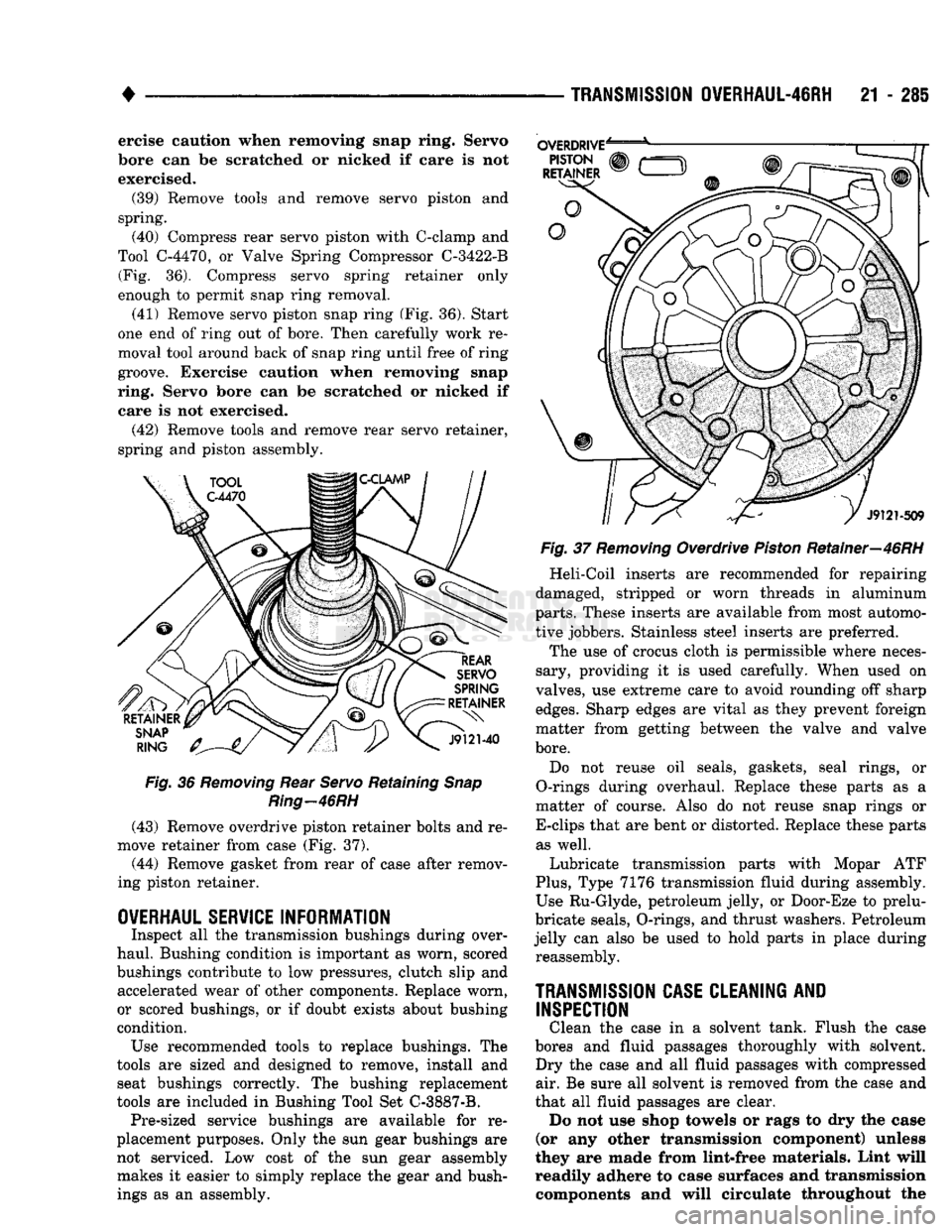
Compress rear servo piston with C-clamp and
Tool C-4470, or Valve Spring Compressor C-3422-B (Fig. 36). Compress servo spring retainer only
enough to permit snap ring removal.
(41) Remove servo piston snap ring (Fig. 36). Start
one end of ring out of bore. Then carefully work re
moval tool around back of snap ring until free of ring
groove. Exercise caution when removing snap
ring. Servo bore can be scratched or nicked if care is not exercised.
(42) Remove tools and remove rear servo retainer,
spring and piston assembly.
Fig.
36
Removing
Rear
Servo
Retaining
Snap
Ring—46RH
(43) Remove overdrive piston retainer bolts and re
move retainer from case (Fig. 37).
(44) Remove gasket from rear of case after remov
ing piston retainer.
OVERHAUL SERVICE
INFORMATION
Inspect all the transmission bushings during over
haul. Bushing condition is important as worn, scored
bushings contribute to low pressures, clutch slip and accelerated wear of other components. Replace worn,
or scored bushings, or if doubt exists about bushing
condition. Use recommended tools to replace bushings. The
tools are sized and designed to remove, install and seat bushings correctly. The bushing replacement
tools are included in Bushing Tool Set C-3887-B. Pre-sized service bushings are available for re
placement purposes. Only the sun gear bushings are not serviced. Low cost of the sun gear assembly makes it easier to simply replace the gear and bushings as an assembly.
Fig.
37
Removing
Overdrive
Piston
Retainer—46RH
Heli-Coil inserts are recommended for repairing
damaged, stripped or worn threads in aluminum
parts.
These inserts are available from most automo
tive jobbers. Stainless steel inserts are preferred.
The use of crocus cloth is permissible where neces
sary, providing it is used carefully. When used on
valves, use extreme care to avoid rounding off sharp
edges.
Sharp edges are vital as they prevent foreign
matter from getting between the valve and valve
bore.
Do not reuse oil seals, gaskets, seal rings, or
O-rings during overhaul. Replace these parts as a
matter of course. Also do not reuse snap rings or
E-clips that are bent or distorted. Replace these parts as well.
Lubricate transmission parts with Mopar ATF
Plus,
Type 7176 transmission fluid during assembly.
Use Ru-Glyde, petroleum jelly, or Door-Eze to prelu-
bricate seals, O-rings, and thrust washers. Petroleum
jelly can also be used to hold parts in place during reassembly.
TRANSMISSION
CASE
CLEANING
AND
INSPECTION
Clean the case in a solvent tank. Flush the case
bores and fluid passages thoroughly with solvent. Dry the case and all fluid passages with compressed air. Be sure all solvent is removed from the case and
that all fluid passages are clear. Do not use shop towels or rags to dry the case
(or any other transmission component) unless
they are made from lint-free materials. Lint will readily adhere to case surfaces and transmission components and will circulate throughout the