height DODGE TRUCK 1993 Service Repair Manual
[x] Cancel search | Manufacturer: DODGE, Model Year: 1993, Model line: TRUCK, Model: DODGE TRUCK 1993Pages: 1502, PDF Size: 80.97 MB
Page 9 of 1502
4 INTRODUCTION
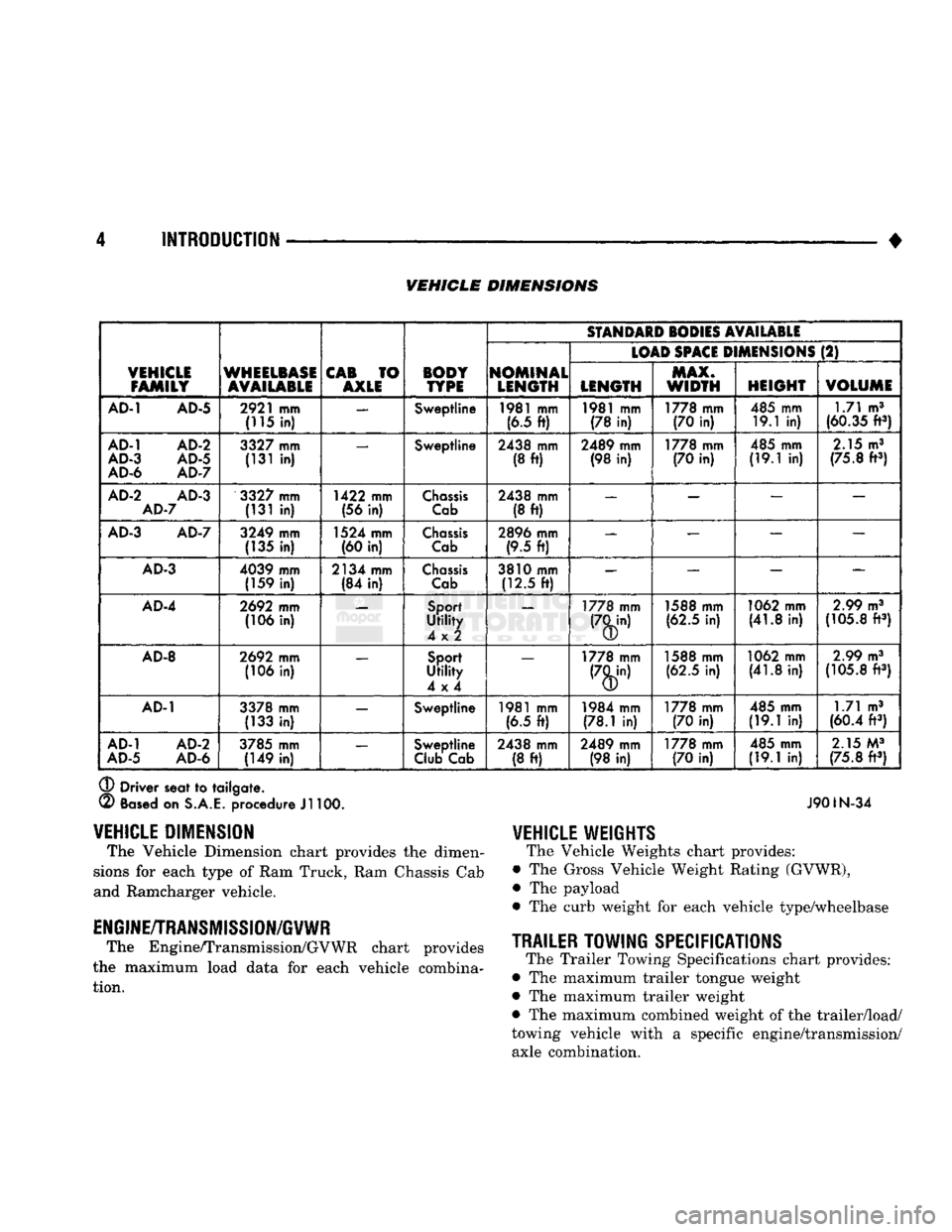
• VEHICLE DIMENSIONS
VEHICLE
FAMILY
WHEELBASE
AVAILABLE
CAB
TO
AXLE BODY
TYPE
SfANDAID
SODIES
AVAILABLE
VEHICLE
FAMILY
WHEELBASE
AVAILABLE
CAB
TO
AXLE BODY
TYPE
NOMINAL
LENGTH
(LOAD
SPACE
D
MENSIONS
(2)
VEHICLE
FAMILY
WHEELBASE
AVAILABLE
CAB
TO
AXLE BODY
TYPE
NOMINAL
LENGTH LENGTH MAX.
WIDTH
HEIGHT
VOLUME
AD-1
AD-5
2921
mm
(115
in) —
Sweptline
1981
mm
(6.5
ft)
1981
mm
(78
in)
1778 mm
(70
in)
485 mm
19.1
in) 1.71 m3
(60.35
ft3)
AD-1
AD-2
AD-3
AD-5
AD-6
AD-7
3327
mm
(131
in) —
Sweptline
2438 mm
(8
ft)
2489 mm
(98
in)
1778 mm
(70
in)
485 mm
(19.1
in)
2.15
m3
(75.8
ft3)
AD-2
AD-3
AD-7
3327
mm
(131
in)
1422 mm
(56
in)
Chassis
Cab
2438 mm
(8
ft)
—
— — —
AD-3
AD-7
3249 mm
(135
in)
1524 mm
(60
in)
Chassis
Cab
2896 mm
(9.5
ft) —
— — —
AD-3
4039 mm
(159
in)
2134 mm
(84
in)
Chassis
Cab
3810 mm
(12.5
ft)
—
— —
AD-4
2692
mm
(106
in)
Sport
Utility
4x2
—
1778 mm 1588 mm
(62.5
in)
1062 mm
(41.8
in)
2.99
m3
(105.8
ft3)
AD-8
2692
mm
(106
in)
Sport
Utility
4x4
—
1778 mm 1588 mm
(62.5
in)
1062 mm
(41.8
in)
2.99
m3
(105.8
ft3)
AD-1
3378 mm
(133
in) —
Sweptline
1981
mm
(6.5
ft)
1984 mm
(78.1
in)
1778 mm
(70
in)
485 mm
(19.1
in) 1.71 m3
(60.4
ft3)
AD-1
AD-2
AD-5
AD-6
3785 mm
(149
in) —
Sweptline
Club
Cab 2438 mm
(8
ft)
2489 mm
(98
in)
1778 mm
(70
in)
485 mm
(19.1
in)
2.15
M3
(75.8
ft3)
®
Driver seat
to
tailgate.
(2)
Based
on
S.A.E.
procedure
Jl
100. J901N-34
VEHICLE
WEIGHTS
The Vehicle Weights chart provides:
• The Gross Vehicle Weight Rating (GVWR),
• The payload
• The curb weight
for
each vehicle type/wheelbase
TRAILER
TOWING
SPECIFICATIONS
The Trailer Towing Specifications chart provides:
• The maximum trailer tongue weight
• The maximum trailer weight
• The maximum combined weight of the trailer/load/
towing vehicle with
a
specific engine/transmission/ axle combination.
VEHICLE
DIMENSION
The Vehicle Dimension chart provides
the
dimen
sions
for
each type
of
Ram Truck, Ram Chassis Cab
and Ramcharger vehicle.
ENGINE/TRANSMISSION/GVWR
The Engine/Transmission/GVWR chart provides
the maximum load data
for
each vehicle combina tion.
Page 59 of 1502
2
- 6
FRONT
SUSPENSION
AND
AXLE
•
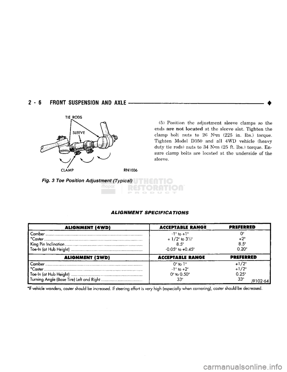
(5) Position the adjustment sleeve clamps so the
ends are not located at the sleeve slot. Tighten the
clamp bolt nuts to 26 N*m (225 in. lbs.) torque.
Tighten Model D350 and all 4WD vehicle (heavy
duty tie rods) nuts to 34 N*m (25 ft. lbs.) torque. En
sure clamp bolts are located at the underside of the
sleeve.
CLAMP
RN1036
Fig.
3 Toe Position Adjustment
(Typical)
ALIGNMENT
SPECIFICATIONS
ALIGNMENT
(4WD)
ASGSPTABLE RANGE
PREFERRED
Camber
-rto+r
0°
"Caster
+
1/2°
to
37*°
+2°
King
Pin
Inclination
8.5° 8.5°
Toe-In
(at
Hub
Height)
-0.05°
to
+0.45° 0.20°
ALIGNMENT
(2WD)
ACCEPTABLE RANGE PREFERRED
Camber
0°to 1°
+1/2°
'Caster
-1°
to
+2°
+1/2°
Toe-in
(at
Hub
Height)
0°
to
0.50° 0.25°
Turning
Angle
(Base
Tire)
Left
and
Right
33°
33°
J9102-64
*lf vehicle
wanders,
caster
should
be increased. If steering
effort
is very
high
(especially when cornering), caster
should
be decreased.
TIE
RODS
Page 60 of 1502
•
FRONT
SUSPENSION
AND
AXLE
2 • 7
FRONT SUSPENSION
—2WD
VEHICLES
INDEX
page
Coil Springs
9
Lower Ball Stud
. 10
Lower Suspension
Arm 10
Lower Suspension
Arm
Bushing
11
Lower Suspension
Arm
Strut
8
Service
Information
7
Shock
Absorber
9
page
Stabilizer
Bar 8
Steering Knuckle
13
Upper Ball Stud
11
Upper Suspension
Arm 11
Upper Suspension
Arm
Bushing Replacement
. . . 12
Wheel
Hub and
Bearings
7
SERVICE
INFORMATION
Periodic lubrication of the front suspension (steer
ing) system components is required. Refer to Group 0, Lubrication And Maintenance for the service in
terval.
Rubber bushings must never be lubricated.
All front suspension components that are
cushioned by rubber should be tightened with
the suspension system at the normal height.
WHEEL
HUB
AND
BEARINGS
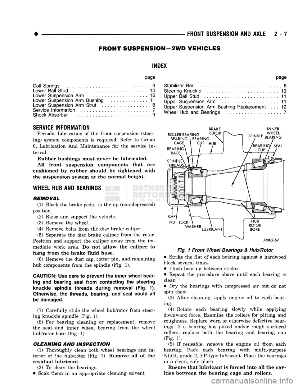
REMOVAL (1) Block the brake pedal in the up (non-depressed)
position.
(2) Raise and support the vehicle.
(3) Remove the wheel.
(4) Remove bolts from the disc brake caliper.
(5) Separate the disc brake caliper from the rotor.
Position and support the caliper away from the im
mediate work area. Do not allow the caliper to
hang from the brake fluid hose.
(6) Remove the dust cap, cotter pin, and remaining
hub components from the spindle (Fig. 1).
CAUTION:
Use care
to
prevent
the
inner wheel bear
ing
and
bearing seal from contacting
the
steering
knuckle spindle threads during removal
(Fig. 1).
Otherwise,
the
threads, bearing,
and
seal could
all
be damaged.
(7) Carefully slide the wheel hub/rotor from steer
ing knuckle spindle (Fig. 1).
(8) For bearing cleaning or replacement, remove
the seal and inner wheel bearing from the wheel
hub/rotor bore (Fig. 1).
CLEANING AND INSPECTION (1) Thoroughly clean both wheel bearings and in
terior of the hub/rotor (Fig. 1). Remove all of the residual lubricant.
(2) To clean the bearings:
• Soak them in an appropriate cleaning solvent
BRAKE
INNER
Fig.
1 Front
Wheel
Bearings
&
Hub/Rotor
• Strike the flat of each bearing against a hardwood
block several times • Flush bearing between strikes
• Repeat the procedure above until each bearing is
clean
• Dry the bearings with compressed air but do not spin them
(3) After cleaning, apply engine oil to each bear
ing. (4) Rotate each bearing slowly while applying
downward force. Examine the rollers for pitting and
roughness. Replace worn or otherwise defective bear
ings.
If a bearing has pitted and/or rough surfaced
rollers, replace both the bearing and bearing cup (Fig. 1).
(5) If reusable, remove the engine oil from each
bearing. Pack each bearing with multi-purpose NLGI, grade 2, EP-type lubricant. Place the bearings
in a clean, safe place.
Ensure that lubricant is forced into all the cav
ities between the bearing cage and rollers.
Page 68 of 1502
•
FRONT
SUSPENSION
AND
AXLE
2 - 15 Ensure the shock absorber is positioned on the
stud with retainers correctly located (Fig. 2).
(2)
Position the inner retainers on the mounting
studs.
(3) Install the shock on the upper and lower stud
and install the outer retainers.
(4) Install the nuts on the frame bracket and axle
(Fig. 2). (5) Tighten the shock absorber upper and lower
nuts;
• Standard shock upper and lower nut to 75 Nnn (55
ft. lbs.) torque
• Air-adjustable shock upper nut to 75 N»m (55 ft. lbs.) torque, lower nut to 271 Nnn (200 ft. lbs.)
torque
CAUTION:
Vehicles
with
air
shocks MUST
maintain
a
minimum
pressure
of 10 to 15 psi (70 to 105 kPa). Operation below the specified minimum
pressures
may cause damage.
(6) Remove the supports and lower the vehicle.
LEAF
SPRINGS
REMOVAL
(1) Raise and support the frame until all weight is
removed from the front springs. (2) With the front tires in contact with the surface,
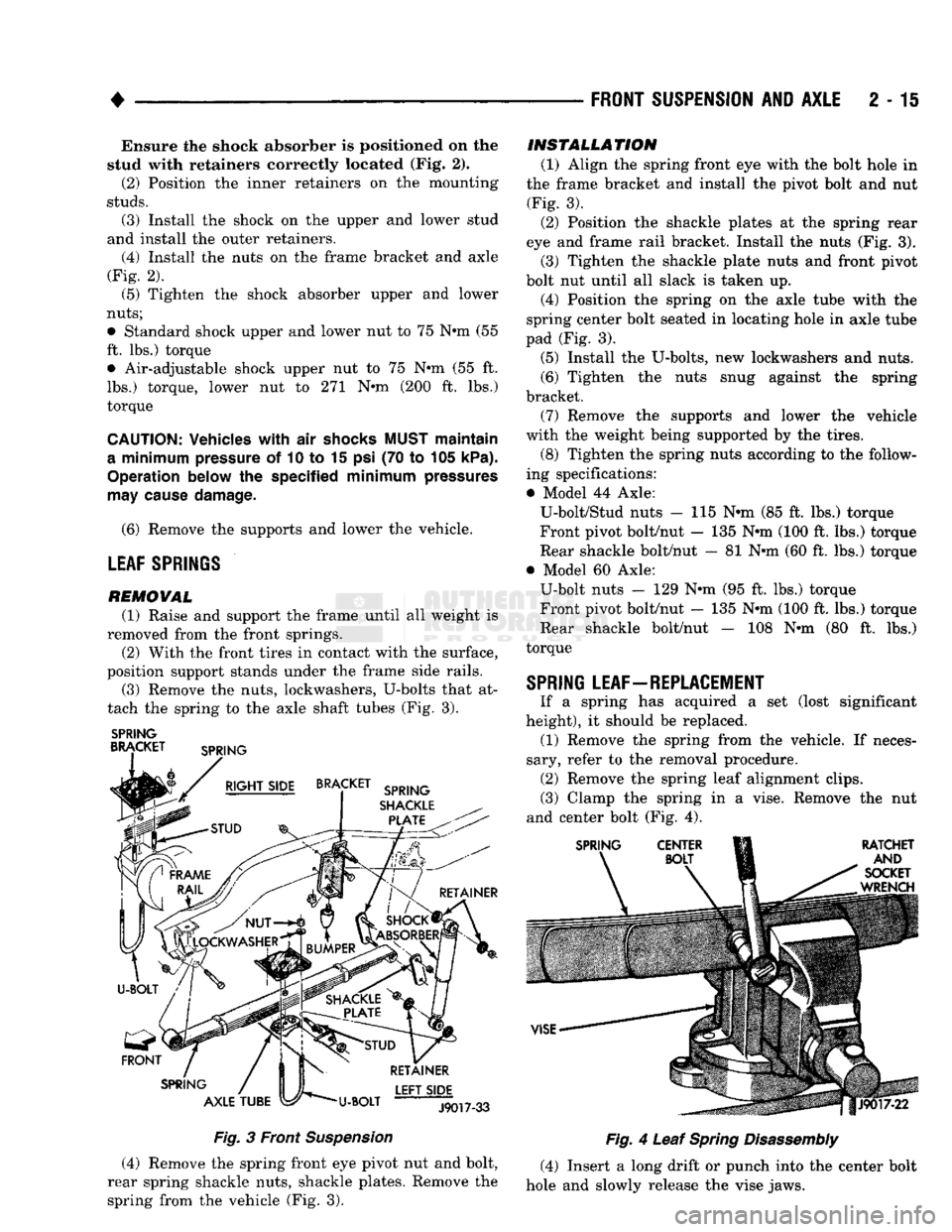
position support stands under the frame side rails. (3) Remove the nuts, lockwashers, U-bolts that at
tach the spring to the axle shaft tubes (Fig. 3).
SPRING
BRACKET SPRING
BRACKET SPRING
SHACKLE
PLATE
FRONT
SPRING
AXLE
TUBE U-BOLT LEFT
SIDE
J9017-33
Fig.
3 Front
Suspension
(4) Remove the spring front eye pivot nut and bolt,
rear spring shackle nuts, shackle plates. Remove the spring from the vehicle (Fig. 3).
INSTALLATION
(1) Align the spring front eye with the bolt hole in
the frame bracket and install the pivot bolt and nut (Fig. 3). (2) Position the shackle plates at the spring rear
eye and frame rail bracket. Install the nuts (Fig. 3). (3) Tighten the shackle plate nuts and front pivot
bolt nut until all slack is taken up. (4) Position the spring on the axle tube with the
spring center bolt seated in locating hole in axle tube
pad (Fig. 3).
(5) Install the U-bolts, new lockwashers and nuts.
(6) Tighten the nuts snug against the spring
bracket.
(7) Remove the supports and lower the vehicle
with the weight being supported by the tires. (8) Tighten the spring nuts according to the follow
ing specifications:
• Model 44 Axle: U-bolt/Stud nuts - 115 Nnn (85 ft. lbs.) torque
Front pivot bolt/nut — 135 Nnn (100 ft. lbs.) torque
Rear shackle bolt/nut — 81 Nnn (60 ft. lbs.) torque
• Model 60 Axle: U-bolt nuts - 129 Nnn (95 ft. lbs.) torque Front pivot bolt/nut - 135 Nnn (100 ft. lbs.) torque
Rear shackle bolt/nut - 108 Nnn (80 ft. lbs.)
torque
SPRING LEAF-REPLACEMENT
If a spring has acquired a set (lost significant
height), it should be replaced. (1) Remove the spring from the vehicle. If neces
sary, refer to the removal procedure. (2) Remove the spring leaf alignment clips.
(3) Clamp the spring in a vise. Remove the nut
and center bolt (Fig. 4).
SPRING
CENTER
RATCHET
AND
SOCKET
WRENCH
Fig.
4 Leaf
Spring
Disassembly
(4) Insert a long drift or punch into the center bolt
hole and slowly release the vise jaws.
Page 91 of 1502
2
- 38
FRONT
SUSPENSION
AND
AXLE
•
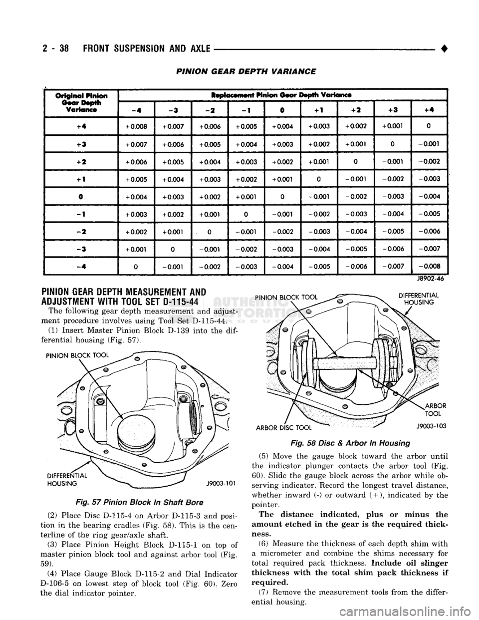
PINION GEAR DEPTH VARIANCE
Or§@ift^i
Linton
IsptocMnwtt
HnS®n
Oior Itoplli
fflttanct
Or§@ift^i
Linton
-4
-2
-1
0
+
1
-ft
+3
+4
+4
+
0.008
+
0.007
+
0.006
+
0.005
+
0.004
+
0.003
+
0.002
+
0.001
0
+3
+
0.007
+
0.006
+
0.005
+
0.004
+
0.003
+
0.002
+
0.001
0
-0.001
+2
+
0.006
+
0.005
+
0.004
+
0.003
+
0.002
+
0.001
0
-0.001
-0.002
+
1
+
0.005
+
0.004
+
0.003
+
0.002
+
0.001
0
-0.001
-0.002
-0.003
0
+
0.004
+
0.003
+
0.002
+
0.001
0
-0.001
-0.002
-0.003
-0.004
-1
+
0.003
+
0.002
+
0.001
0
-0.001
-0.002
-0.003 -0.004
-0.005
-2
+
0.002
+
0.001
. 0
-0.001
-0.002
-0.003 -0.004
-0.005 -0.006
-3
+
0.001
0
-0.001
-0.002
-0.003 -0.004
-0.005 -0.006
-0.007
-.4
0
-0.001
-0.002
-0.003 -0.004 -0.005
-0.006
-0.007
-0.008
PINION
GEAR
DEPTH
MEASUREMENT
AND
ADJUSTMENT
WITH TOOL SET D-11144
The following gear depth measurement and adjust
ment procedure involves using Tool Set D-115-44. (1) Insert Master Pinion Block D-139 into the
dif
ferential housing (Fig. 57).
PINION BLOCK TOOL PINION BLOCK TOOL
J8902-46
DIFFERENTIAL
HOUSING
ARBOR
DISC
TOOL
ARBOR
TOOL
J9003-103
DIFFERENTIAL
HOUSING
J9003-101
Fig.
57
Pinion
Block
In Shaft
Bore
(2) Place Disc D-115-4 on Arbor D-115-3 and posi
tion in the bearing cradles (Fig. 58). This is the cen
terline of the ring gear/axle shaft. (3) Place Pinion Height Block D-115-1 on top of
master pinion block tool and against arbor tool (Fig.
59).
(4) Place Gauge Block D-115-2 and Dial Indicator
D-106-5 on lowest step of block tool (Fig. 60). Zero
the dial indicator pointer.
Fig.
58
Disc
&
Arbor
In
Housing
(5) Move the gauge block toward the arbor until
the indicator plunger contacts the arbor tool (Fig.
60).
Slide the gauge block across the arbor while ob
serving indicator. Record the longest travel distance,
whether inward (-) or outward (+•), indicated by the
pointer.
The distance indicated, plus or minus the
amount etched in the gear is the required thick
ness.
(6) Measure the thickness of each depth shim with
a micrometer and combine the shims necessary for
total required pack thickness. Include oil slinger
thickness with the total shim pack thickness if
required.
(7) Remove the measurement tools from the differ
ential housing.
Page 92 of 1502
•
FRONT
SUSPENSION
AND
AXLE
2 - 39
Fig.
59
Pinion
Height
Block
Against
Arbor
Fig.
60
Pinion
Gear Depth Measurement
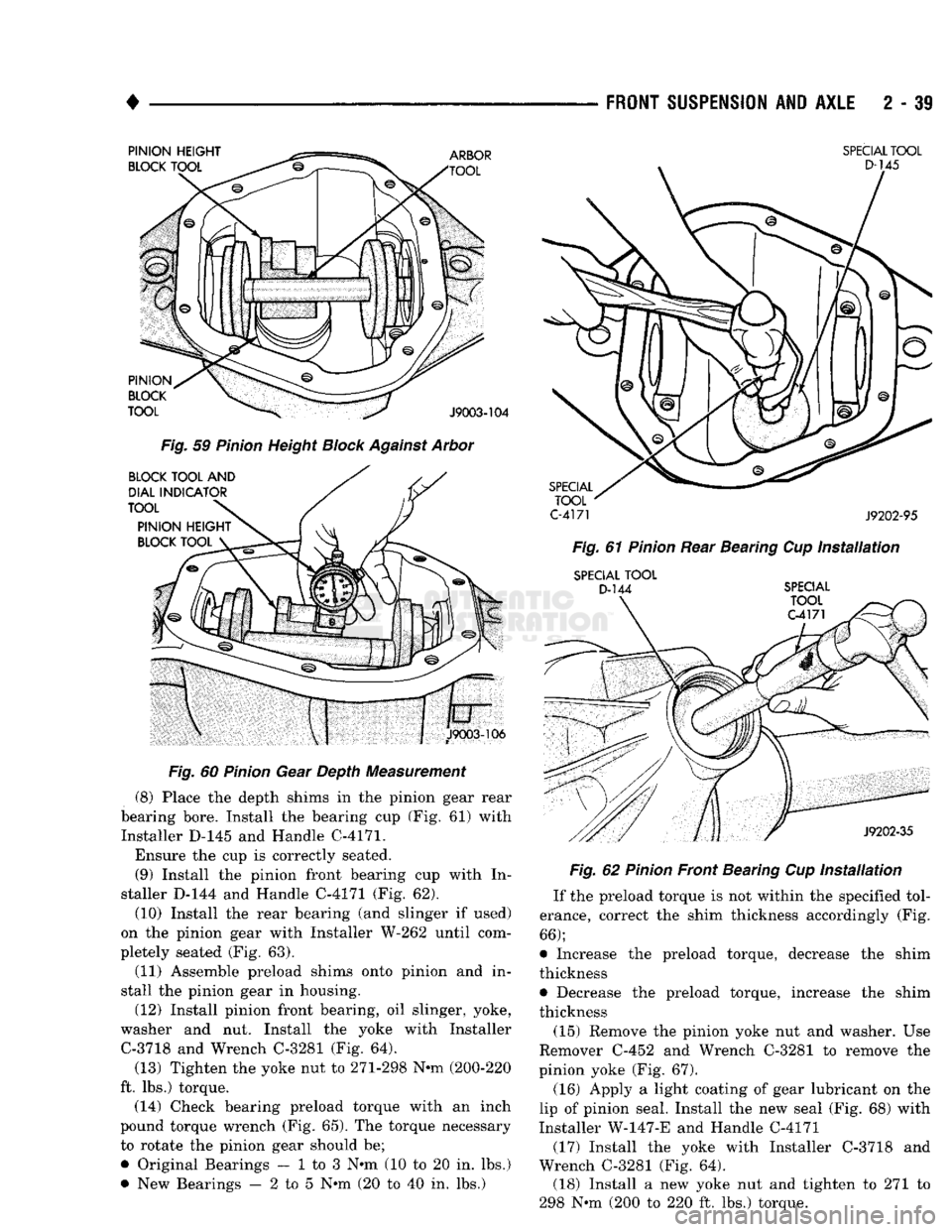
(8) Place the depth shims in the pinion gear rear
bearing bore. Install the bearing cup (Fig. 61) with Installer D-145 and Handle C-4171.
Ensure the cup is correctly seated. (9) Install the pinion front bearing cup with In
staller D-144 and Handle C-4171 (Fig. 62).
(10) Install the rear bearing (and slinger if used)
on the pinion gear with Installer W-262 until com
pletely seated (Fig. 63).
(11) Assemble preload shims onto pinion and in
stall the pinion gear in housing.
(12) Install pinion front bearing, oil slinger, yoke,
washer and nut. Install the yoke with Installer C-3718 and Wrench C-3281 (Fig. 64).
(13) Tighten the yoke nut to 271-298 N-m (200-220
ft. lbs.) torque. (14) Check bearing preload torque with an inch
pound torque wrench (Fig. 65). The torque necessary
to rotate the pinion gear should be;
• Original Bearings — 1 to 3 N*m (10 to 20 in. lbs.)
• New Bearings — 2 to 5 N*m (20 to 40 in. lbs.)
SPECIAL
TOOL
C-4171
J9202-95
Fig.
61
Pinion
Rear Bearing Cup
Installation
SPECIAL
TOOL
D-144
SPECIAL Fig.
62
Pinion
Front Bearing Cup
Installation
If the preload torque is not within the specified tol
erance, correct the shim thickness accordingly (Fig.
66);
• Increase the preload torque, decrease the shim
thickness
• Decrease the preload torque, increase the shim
thickness
(15) Remove the pinion yoke nut and washer. Use
Remover C-452 and Wrench C-3281 to remove the
pinion yoke (Fig. 67).
(16) Apply a light coating of gear lubricant on the
lip of pinion seal. Install the new seal (Fig. 68) with
Installer W-147-E and Handle C-4171
(17) Install the yoke with Installer C-3718 and
Wrench C-3281 (Fig. 64). (18) Install a new yoke nut and tighten to 271 to
298 N-m (200 to 220 ft. lbs.) torque.
Page 112 of 1502
•
TAPERED
BUSHING
J9202-53
Fig.
32 Tapered
Bushing
Installation
J9202-52
Fig.
33
Lower
King
Pin and Retainer
Installation
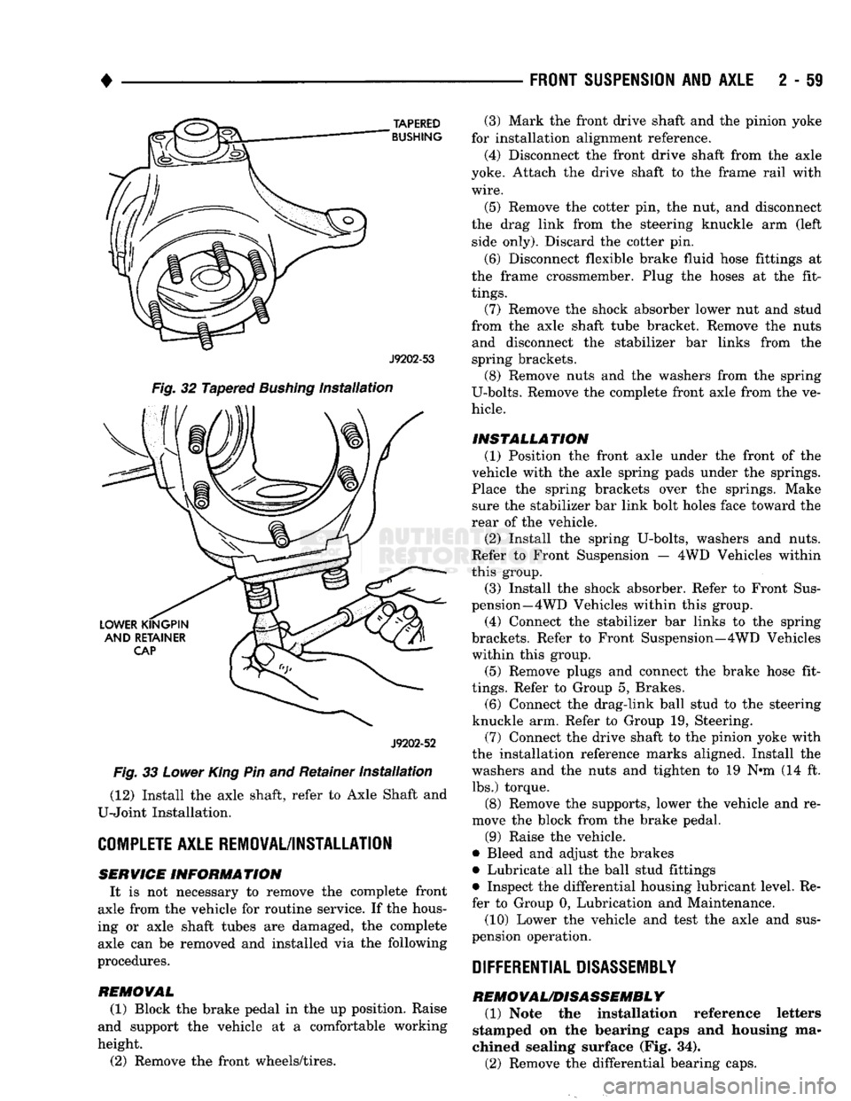
(12) Install the axle shaft, refer to Axle Shaft and
U-Joint Installation.
COMPLETE
AXLE REMOVAL/INSTALLATION SERVICE
INFORMATION
It is not necessary to remove the complete front
axle from the vehicle for routine service. If the hous
ing or axle shaft tubes are damaged, the complete axle can be removed and installed via the following
procedures.
REMOVAL
(1) Block the brake pedal in the up position. Raise
and support the vehicle at a comfortable working
height.
(2) Remove the front wheels/tires.
FRONT SUSPENSION
AND
AXLE
2 - 59
(3) Mark the front drive shaft and the pinion yoke
for installation alignment reference.
(4) Disconnect the front drive shaft from the axle
yoke. Attach the drive shaft to the frame rail with
wire.
(5) Remove the cotter pin, the nut, and disconnect
the drag link from the steering knuckle arm (left side only). Discard the cotter pin.
(6) Disconnect flexible brake fluid hose fittings at
the frame crossmember. Plug the hoses at the fit
tings.
(7) Remove the shock absorber lower nut and stud
from the axle shaft tube bracket. Remove the nuts and disconnect the stabilizer bar links from the
spring brackets. (8) Remove nuts and the washers from the spring
U-bolts. Remove the complete front axle from the ve
hicle.
INSTALLATION (1) Position the front axle under the front of the
vehicle with the axle spring pads under the springs.
Place the spring brackets over the springs. Make sure the stabilizer bar link bolt holes face toward the
rear of the vehicle.
(2) Install the spring U-bolts, washers and nuts.
Refer to Front Suspension — 4WD Vehicles within
this group. (3) Install the shock absorber. Refer to Front Sus
pension—4 WD Vehicles within this group.
(4) Connect the stabilizer bar links to the spring
brackets. Refer to Front Suspension—4WD Vehicles within this group.
(5) Remove plugs and connect the brake hose fit
tings.
Refer to Group 5, Brakes. (6) Connect the drag-link ball stud to the steering
knuckle arm. Refer to Group 19, Steering. (7) Connect the drive shaft to the pinion yoke with
the installation reference marks aligned. Install the
washers and the nuts and tighten to 19 N-m (14 ft. lbs.) torque.
(8) Remove the supports, lower the vehicle and re
move the block from the brake pedal.
(9) Raise the vehicle.
• Bleed and adjust the brakes
• Lubricate all the ball stud fittings
• Inspect the differential housing lubricant level. Re
fer to Group 0, Lubrication and Maintenance.
(10) Lower the vehicle and test the axle and sus
pension operation.
DIFFERENTIAL DISASSEMBLY
REMOVAL/DISASSEMBLY
(1) Note the installation reference letters
stamped on the bearing caps and housing ma
chined sealing surface (Fig. 34).
(2) Remove the differential bearing caps.
Page 119 of 1502
2
- 66
FRONT
SUSPENSION
AND
AXLE
•
PINION
GEAR
DEPTH
MEASUREMENT
AND
ADJUSTMENT
WITH
TOOL
SET
D-116 The following gear depth measurement and adjust
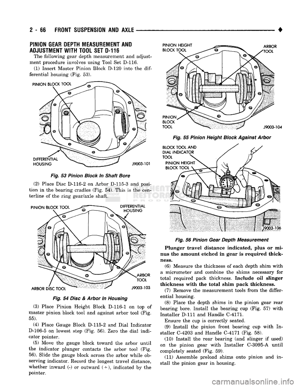
ment procedure involves using Tool Set D-116. (1) Insert Master Pinion Block D-120 into the
dif
ferential housing (Fig. 53).
Fig.
53
Pinion
Block
In Shaft
Bore
(2) Place Disc D-116-2 on Arbor D-115-3 and posi
tion in the bearing cradles (Fig. 54). This is the cen
terline of the ring gear/axle shaft.
Fig.
54
Disc
&
Arbor
In
Housing
(3) Place Pinion Height Block D-116-1 on top of
master pinion block tool and against arbor tool (Fig.
55).
(4) Place Gauge Block D-115-2 and Dial Indicator
D-106-5 on lowest step (Fig. 56). Zero the dial indi
cator pointer.
(5) Move the gauge block toward the arbor until
the indicator plunger contacts the arbor tool (Fig.
56).
Slide the gauge block across the arbor while ob
serving indicator. Record the longest travel distance,
whether inward (-) or outward
(
+ ), indicated by the
pointer.
Fig.
55
Pinion
Height
Block
Against
Arbor
Fig.
56
Pinion
Gear Depth Measurement
Plunger travel distance indicated, plus or mi
nus the amount etched in gear is required thick
ness.
(6) Measure the thickness of each depth shim with
a micrometer and combine the shims necessary for
total required pack thickness. Include oil slinger
thickness with the total shim pack thickness.
(7) Remove the measurement tools from the differ
ential housing.
(8) Place the depth shims in the pinion gear rear
bearing bore. Install the bearing cup (Fig. 57) with
Installer D-lll and Handle C-4171.
Ensure the cup is correctly seated. (9) Install the pinion front bearing cup with In
staller C-4203 and Handle C-4171 (Fig. 58). (10) Install the rear bearing (and slinger if used)
on the pinion gear with Installer C-3095-A until
completely seated (Fig. 59).
(11) Assemble preload shims onto pinion and in
stall the pinion gear in housing.
Page 134 of 1502
•
Fig.
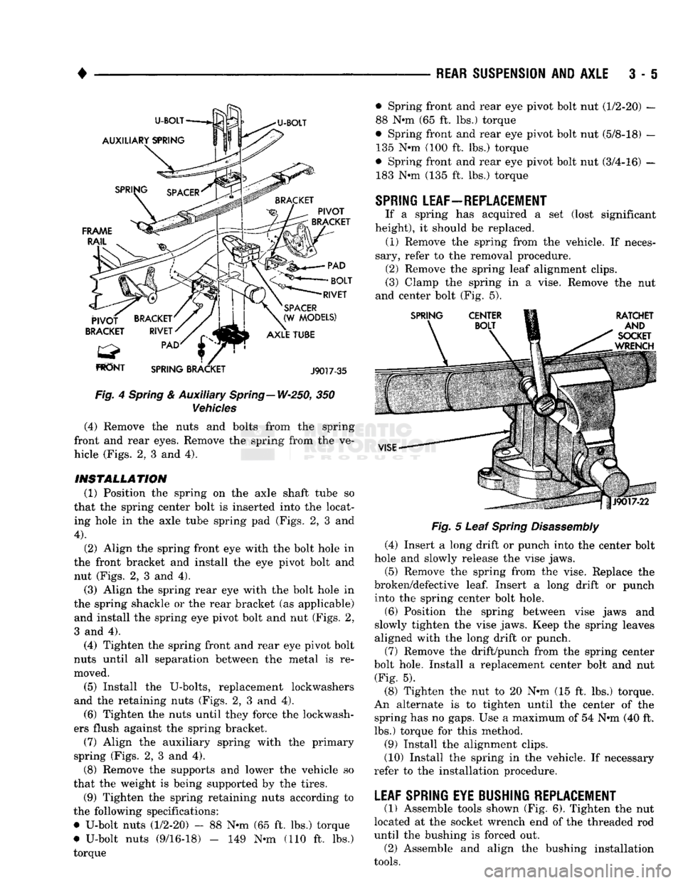
4
Spring
& Auxiliary Spring—W-250, 350
Vehicles
(4) Remove the nuts and bolts from the spring
front and rear eyes. Remove the spring from the ve
hicle (Figs. 2, 3 and 4).
INSTALLATION (1) Position the spring on the axle shaft tube so
that the spring center bolt is inserted into the locat ing hole in the axle tube spring pad (Figs. 2, 3 and
4).
(2) Align the spring front eye with the bolt hole in
the front bracket and install the eye pivot bolt and nut (Figs. 2, 3 and 4). (3) Align the spring rear eye with the bolt hole in
the spring shackle or the rear bracket (as applicable) and install the spring eye pivot bolt and nut (Figs. 2,
3 and 4).
(4) Tighten the spring front and rear eye pivot bolt
nuts until all separation between the metal is re
moved.
(5) Install the U-bolts, replacement lockwashers
and the retaining nuts (Figs. 2, 3 and 4). (6) Tighten the nuts until they force the lockwash
ers flush against the spring bracket. (7) Align the auxiliary spring with the primary
spring (Figs. 2, 3 and 4).
(8) Remove the supports and lower the vehicle so
that the weight is being supported by the tires.
(9) Tighten the spring retaining nuts according to
the following specifications:
• U-bolt nuts (1/2-20) - 88 N*m (65 ft. lbs.) torque
# U-bolt nuts (9/16-18) - 149 N-m (110 ft. lbs.)
torque —
REAR SUSPENSION
AND
AXLE
3 • 5
Fig.
5 Leaf
Spring
Disassembly
(4) Insert a long drift or punch into the center bolt
hole and slowly release the vise jaws.
(5) Remove the spring from the vise. Replace the
broken/defective
leaf.
Insert a long drift or punch into the spring center bolt hole.
(6) Position the spring between vise jaws and
slowly tighten the vise jaws. Keep the spring leaves
aligned with the long drift or punch.
(7) Remove the drift/punch from the spring center
bolt hole. Install a replacement center bolt and nut (Fig. 5).
(8) Tighten the nut to 20 N-m (15 ft. lbs.) torque.
An alternate is to tighten until the center of the spring has no gaps. Use a maximum of 54 N*m (40 ft.
lbs.) torque for this method.
(9) Install the alignment clips.
(10) Install the spring in the vehicle. If necessary
refer to the installation procedure.
LEAF SPRING EYE BUSHING REPLACEMENT
(1) Assemble tools shown (Fig. 6). Tighten the nut
located at the socket wrench end of the threaded rod
until the bushing is forced out. (2) Assemble and align the bushing installation
tools.
• Spring front and rear eye pivot bolt nut (1/2-20) —
88 N«m (65 ft. lbs.) torque
© Spring front and rear eye pivot bolt nut (5/8-18) — 135 N»m (100 ft. lbs.) torque
• Spring front and rear eye pivot bolt nut (3/4-16) — 183 N-m (135 ft. lbs.) torque
SPRING
LEAF—REPLACEMENT
If a spring has acquired a set (lost significant
height), it should be replaced. (1) Remove the spring from the vehicle. If neces
sary, refer to the removal procedure. (2) Remove the spring leaf alignment clips.
(3) Clamp the spring in a vise. Remove the nut
and center bolt (Fig. 5).
Page 143 of 1502
3
- 14
REAR SUSPENSION
AND
AXLE
3
- 18
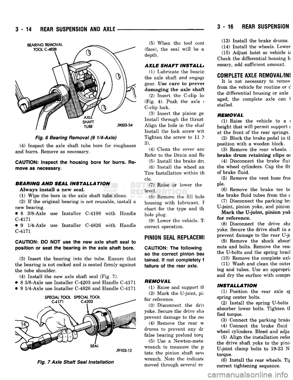
REAR SUSPENSION Fig.
6 Bearing
Removal
(9
1/4-Axle)
(4) Inspect the axle shaft tube bore for roughness
and burrs. Remove as necessary.
CAUTION:
Inspect
the
housing
bore for
burrs.
Re
move
as
necessary.
BEARING
AND
SEAL
INSTALLATION
Always install a new seal. (1) Wipe the bore in the axle shaft tube clean.
(2) If the original bearing is not reusable, install a
new bearing.
• 8 3/8-Axle use Installer C-4198 with Handle
C-4171
• 9
1/4-Axle
use Installer C-4826 with Handle
C-4171
CAUTION:
DO NOT use the new axle
shaft
seal
to
position
or
seat
the bearing in the axle
shaft
bore.
(3) Insert the bearing into the tube. Ensure that
the bearing is not cocked and is seated firmly against
the tube shoulder.
(4) Install the new axle shaft seal (Fig. 7).
• 8 3/8-Axle use Installer C-4203 and Handle C-4171
• 9
1/4-Axle
use Installer C-4826 and Handle C-4171
SPECIAL
TOOL
SPECIAL
TOOL
Fig.
7 Axle Shaft
Seal
Installation
(5) When the tool cont
(face),
the seal will be a
depth.
AXLE SHAFT INSTALL* (1) Lubricate the bearin
the axle shaft and engage gear. Use care to prevei damaging the axle shaft
(2) Insert the C-clip loi
(Fig. 4). Push the axle s
C-clip lock.
(3) Insert the pinion ge
Install through the thrust
Align the hole in the shaf
Install the lock screw wit
Tighten the screw to 11 Is
3).
(4) Clean the cover anc
Refer to the Drain and Re
(5) Install the brake drv
(6) Install the wheel an
Tire Installation within th
cle.
(7) Raise or lower the
level.
(8) Remove the fill hole
housing with lubricant. I chart for the type and th
hole plug.
(9) Lower the vehicle. T
correct operation.
PINION
SEAL REPLACE!!
CAUTION:
The following
so
the correct pinion bea
tained.
If not completely f
failure
of the rear axle.
REMOVAL (1) Raise and support tr
(2) Mark the U-joint, pi]
for reference.
(3) Disconnect the drh
yoke. Secure the drive sha
prevent damage to the re*
(4) Remove the rear w
drums to prevent any dr
false bearing preload torq
(5) Use a Newton-mete
wrench to measure the p
tate the pinion shaft sev( wrench. Note the indicate moved through several re' (13) Install the brake drums.
(14) Install the wheels. Lower
(15) Adjust hoist so vehicle k
Check the differential housing h
essary, add sufficient amount.
COMPLETE AXLE REMOVAL/IN!
It is not necessary to remov
from the vehicle for routine or d
the differential housing or axle aged, the complete axle can 1
stalled.
REMOVAL (1) Raise the vehicle to a <
height that will permit support t at the front of the rear springs. (2) Block the brake pedal in tl
position with a wooden block. (3) Remove the rear wheels. '.
brake drum retaining clips oi
(4) Disconnect the brake flui
the wheel cylinders. Cap the fit of brake fluid.
(5) Remove the vent hose froi
pie.
(6) Remove the brake tee be
the brake fluid tubes from the c (7) Disconnect the parking bn
U-joint, pinion yoke, and pinion
Mark the U-joint, pinion yol
for reference. (8) Disconnect the drive she
yoke. Secure the drive shaft in a prevent damage to the rear U-jc
(9) Remove the shock absorl
nuts and bolts. Remove the reai
the U-bolts and the spring brad
(10) Remove the complete axL
(11) Wash and clean the outei
ing and tubes. Use an appropri; and dry the surface with comprc
INSTALLATION
(1) Position the rear axle sj
spring center bolts.
(2) Install the spring U-bolts
absorber lower bolts. Tighten tl
fled torque.
(3) Connect the parking brake
(4) Connect the brake fluid
wheel cylinders. Bleed and adjui (5) Align the installation refer
the drive shaft yoke to the pinii U-joint clamp bolts to 19-23 N
torque.
(6) Install the rear wheels. Ti|
correct tightening sequence.