inflation pressure DODGE TRUCK 1993 Service Repair Manual
[x] Cancel search | Manufacturer: DODGE, Model Year: 1993, Model line: TRUCK, Model: DODGE TRUCK 1993Pages: 1502, PDF Size: 80.97 MB
Page 6 of 1502
INTRODUCTION
INTRODUCTION
DESIGNATIONS,
LABELS/PLATES/DECALS,
CODES
AND DIMENSIONS/WEIGHTS .
CONTENTS
page
MEASUREMENT
AND TORQUE
... 1 SPECIFICATIONS
page
. 11
DESIGNATIONS, LABELS/PLATES/DECALS, CODES
AND
DIMENSIONS/WEIGHTS
INDEX
page
Engine
and
Transmission/Transfer
Case
Identification
2
Engine/Transmission/GVWR
4
Equipment
Identification
Plate
3
International
Vehicle Control
and
Display
Symbols
10
Major Component
Identification 3
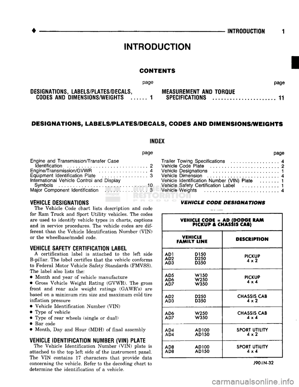
VEHICLE DESIGNATIONS The Vehicle Code chart lists description and code
for Ram Truck and Sport Utility vehicles. The codes are used to identify vehicle types in charts, captions
and in service procedures. The vehicle codes are
dif
ferent than the Vehicle Identification Number (VIN) or the wheelbase/model code.
VEHICLE SAFETY CERTIFICATION
LABEL
A certification label is attached to the left side
B-pillar. The label certifies that the vehicle conforms
to Federal Motor Vehicle Safety Standards (FMVSS).
The label also lists the: • Month and year of vehicle manufacture
• Gross Vehicle Weight Rating (GVWR). The gross
front and rear axle weight ratings (GAWR's) are
based on a minimum rim size and maximum cold tire inflation pressure Vehicle Identification Number (VIN)
Type of vehicle
Type of rear wheels (single or dual) Bar code
Month, Day and Hour (MDH) of final assembly
VEHICLE IDENTIFICATION NUMBER (VIN) PLATE The Vehicle Identification Number (VIN) plate is
attached to the top left side of the instrument panel.
The VIN contains 17 characters that provide data
concerning the vehicle. Refer to the decoding chart to
determine the identification of a vehicle.
page
Trailer
Towing Specifications
4
Vehicle Code Plate
2
Vehicle Designations
1
Vehicle Dimension
4
Vehicle
Identification
Number (VIN) Plate
1
Vehicle Safety
Certification
Label
............. 1
Vehicle Weights
4
VEHICLE CODE
DESIGNATIONS
VEHICLE CODE
= AD
(DODGE
RAM
PICKUP
&
CHASSIS
CAB)
VEHICLE
FAMILY LINE DESCRIPTION
AD1
D150
AD2
D250
AD3
D350
PICKUP
4x2
AD5
W150
AD6
W250
AD7
W350
PICKUP
4x4
AD2
D250
AD3
D350
CHASSIS
CAB
4x2
AD6
W250
AD7
W350
CHASSIS
CAB
4x4
AD4
AD100
AD4
AD150
SPORT
UTILITY
4x2
AD8
AD100
AD8 AD
150
SPORT
UTILITY
4x4
J90IN-32
Page 21 of 1502
0 - 2
LUBRICATION
AND
MAINTENANCE
• Commercial service
When a vehicle is continuously subjected to severe
driving conditions, lubricate:
• Body components
• All the driveline coupling joints
• Steering linkage More often than normal driving conditions
DUSTY
AREAS
With this type of severe driving condition, special
care should be given to the:
• Engine air cleaner filter
• PCV filter
• Crankcase ventilation system
• Brake booster control valve air filter. Verify that the filters and the associated compo
nents are clean. Also verify that they are functioning
effectively. This will minimize the amount of abra sive particles that enter the engine.
OFF-ROAD
(4WD)
OPERATION
After off-road (4WD) operation, inspect the under
side of the vehicle. Inspect the:
• Tires
• Body structure
• Steering components
• Suspension components • Exhaust system
• Threaded fasteners
HARSH
SURFACE ENVIRONMENTS
After extended operation in harsh environments,
the brake drums, brake linings, and rear wheel bear ings should be inspected and cleaned. This will pre
vent wear and erratic brake action.
ROUTINE MAINTENANCE
The following routine maintenance is recommended
on a monthly basis: TIRES—Inspect the tires for unusual wear/damage.
Determine if the inflation pressure is adequate for
the vehicle load. BATTERY—Inspect and clean the terminals.
Tighten the terminals if necessary. FLUIDS—Determine if the component fluid levels
are acceptable. Add fluid, if necessary. LIGHTS/ELECTRICAL—Test all the electrical sys
tems in the vehicle for proper operation. It is also recommended that the engine oil and the
washer fluid level be determined at each fuel fill-up.
VEHICLE
NOISE CONTROL
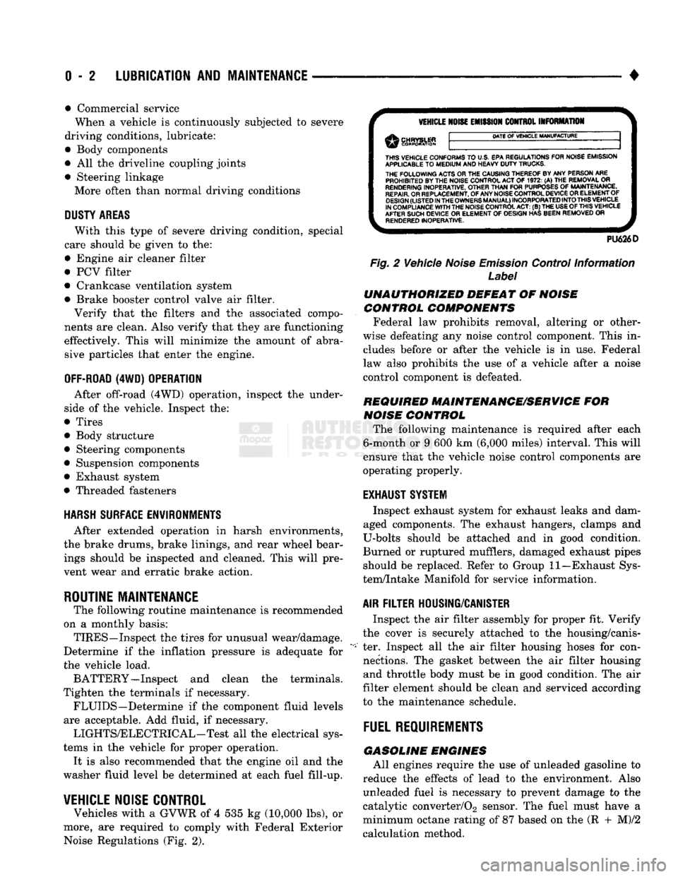
Vehicles with a GVWR of 4 535 kg (10,000 lbs), or
more, are required to comply with Federal Exterior Noise Regulations (Fig. 2).
VEHICLE
NOISE
EMISSION
CONTROL INFORMATION
DATE
OF
VEHICLE
MANUFACTURE
THIS
VEHICLE CONFORMS
TO
U.S. EPA REGULATIONS FOR NOISE EMISSION
APPLICABLE
TO
MEDIUM
AND HEAVY
DUTY
TRUCKS. THE
FOLLOWING
ACTS OR THE CAUSING THEREOF BY ANY PERSON ARE PROHIBITED BY THE NOISE CONTROL ACT
OF 1972. (A) THE
REMOVAL
OR
RENDERING
INOPERATIVE, OTHER
THAN
FOR
PURPOSES
OF
MAINTENANCE,
REPAIR.
OR REPLACEMENT, OF ANY NOISE CONTROL DEVICE OR ELEMENT OF
DESIGN
(LISTED
IN
THE
OWNERS
MANUAL)
INCORPORATED
INTO
THIS
VEHICLE
IN COMPLIANCE
WITH
THE NOISE CONTROL
ACT:
(B) THE
USE
OF
THIS
VEHICLE
AFTER SUCH DEVICE
OR
ELEMENT
OF
DESIGN HAS BEEN REMOVED
OR
RENDERED
INOPERATIVE.
PU626D
Fig.
2 Vehicle
Noise
Emission
Control Information
Label
UNAUTHORIZED
DEFEAT
OF
NOISE
CONTROL COMPONENTS
Federal law prohibits removal, altering or other
wise defeating any noise control component. This in
cludes before or after the vehicle is in use. Federal
law also prohibits the use of a vehicle after a noise
control component is defeated.
REQUIRED MAINTENANCE/SERVICE
FOR
NOISE
CONTROL
The following maintenance is required after each
6-month or 9 600 km (6,000 miles) interval. This will
ensure that the vehicle noise control components are
operating properly.
EXHAUST SYSTEM
Inspect exhaust system for exhaust leaks and dam
aged components. The exhaust hangers, clamps and
U-bolts should be attached and in good condition.
Burned or ruptured mufflers, damaged exhaust pipes should be replaced. Refer to Group 11—Exhaust Sys
tem/Intake Manifold for service information.
AIR
FILTER
HOUSING/CANISTER
Inspect the air filter assembly for proper fit. Verify
the cover is securely attached to the housing/canis
ter. Inspect all the air filter housing hoses for con nections. The gasket between the air filter housing and throttle body must be in good condition. The air
filter element should be clean and serviced according
to the maintenance schedule.
FUEL
REQUIREMENTS
GASOLINE
ENGINES
All engines require the use of unleaded gasoline to
reduce the effects of lead to the environment. Also unleaded fuel is necessary to prevent damage to the
catalytic converter/02 sensor. The fuel must have a
minimum octane rating of 87 based on the (R + M)/2
calculation method.
Page 51 of 1502
0
- 32
LUBRICATION
AND
MAINTENANCE
•
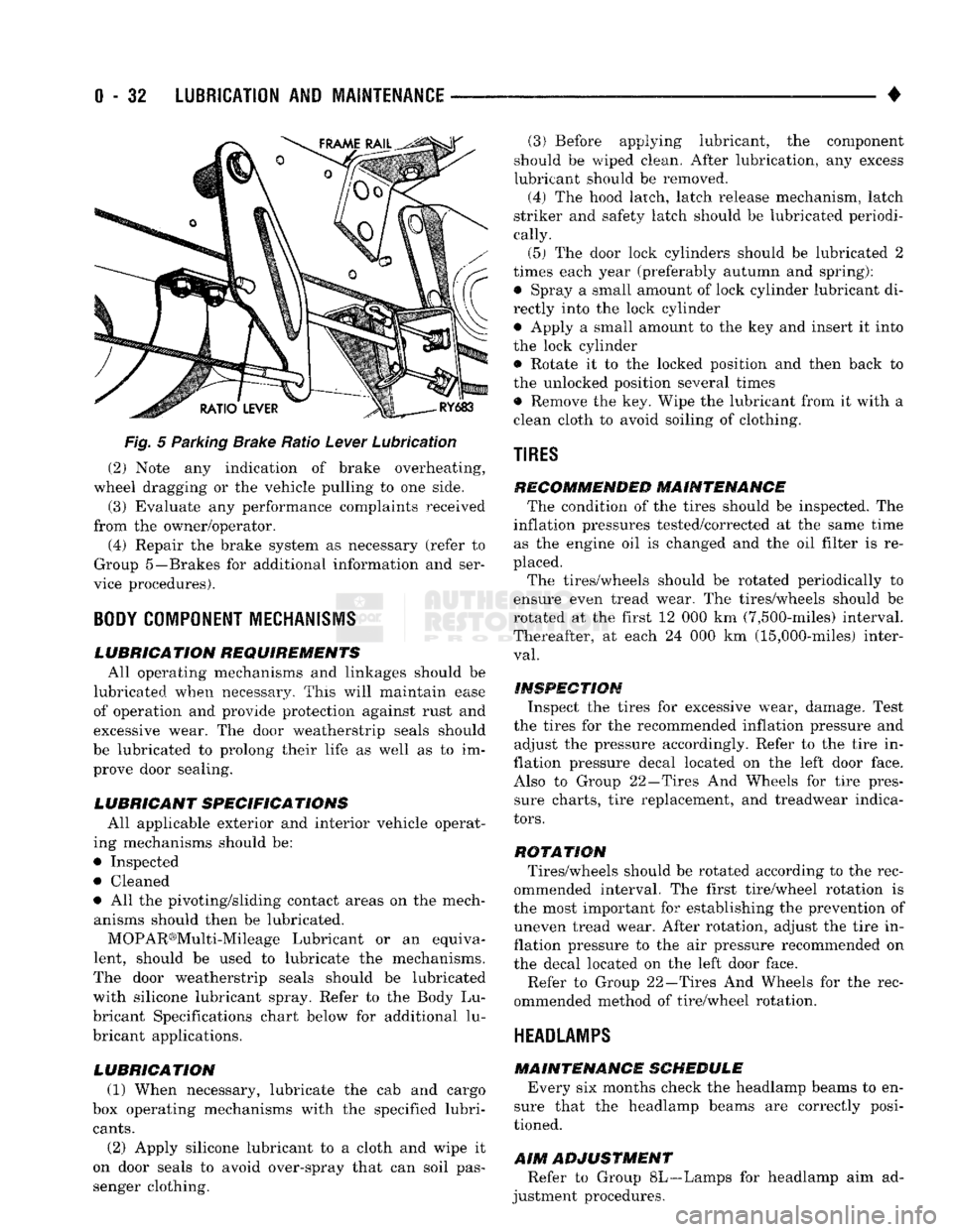
Fig.
5 Parking Brake Ratio Lever Lubrication (2) Note any indication of brake overheating,
wheel dragging or the vehicle pulling to one side.
(3) Evaluate any performance complaints received
from the owner/operator. (4) Repair the brake system as necessary (refer to
Group 5—Brakes for additional information and ser
vice procedures).
BODY
COMPONENT
MECHANISMS
LUBRICATION REQUIREMENTS
All operating mechanisms and linkages should be
lubricated when necessary. This will maintain ease of operation and provide protection against rust and
excessive wear. The door weatherstrip seals should
be lubricated to prolong their life as well as to im prove door sealing.
LUBRICANT SPECIFICATIONS
All applicable exterior and interior vehicle operat
ing mechanisms should be:
• Inspected • Cleaned
• All the pivoting/sliding contact areas on the mech anisms should then be lubricated.
MOPAR®Multi-Mileage Lubricant or an equiva
lent, should be used to lubricate the mechanisms.
The door weatherstrip seals should be lubricated
with silicone lubricant spray. Refer to the Body Lu
bricant Specifications chart below for additional lu
bricant applications.
LUBRICATION
(1) When necessary, lubricate the cab and cargo
box operating mechanisms with the specified lubri
cants.
(2) Apply silicone lubricant to a cloth and wipe it
on door seals to avoid over-spray that can soil pas
senger clothing. (3) Before applying lubricant, the component
should be wiped clean. After lubrication, any excess
lubricant should be removed.
(4) The hood latch, latch release mechanism, latch
striker and safety latch should be lubricated periodi
cally.
(5) The door lock cylinders should be lubricated 2
times each year (preferably autumn and spring): • Spray a small amount of lock cylinder lubricant di
rectly into the lock cylinder
• Apply a small amount to the key and insert it into
the lock cylinder • Rotate it to the locked position and then back to
the unlocked position several times
• Remove the key. Wipe the lubricant from it with a
clean cloth to avoid soiling of clothing.
TIRES
RECOMMENDED MAINTENANCE
The condition of the tires should be inspected. The
inflation pressures tested/corrected at the same time as the engine oil is changed and the oil filter is re
placed.
The tires/wheels should be rotated periodically to
ensure even tread wear. The tires/wheels should be
rotated at the first 12 000 km (7,500-miles) interval.
Thereafter, at each 24 000 km (15,000-miles) inter
val.
INSPECTION
Inspect the tires for excessive wear, damage. Test
the tires for the recommended inflation pressure and adjust the pressure accordingly. Refer to the tire in
flation pressure decal located on the left door face. Also to Group 22—Tires And Wheels for tire pressure charts, tire replacement, and treadwear indica
tors.
ROTATION
Tires/wheels should be rotated according to the rec
ommended interval. The first tire/wheel rotation is
the most important for establishing the prevention of uneven tread wear. After rotation, adjust the tire in
flation pressure to the air pressure recommended on
the decal located on the left door face.
Refer to Group 22—Tires And Wheels for the rec
ommended method of tire/wheel rotation.
HEADLAMPS
MAINTENANCE SCHEDULE
Every six months check the headlamp beams to en
sure that the headlamp beams are correctly posi
tioned.
AIM
ADJUSTMENT
Refer to Group 8L—Lamps for headlamp aim ad
justment procedures.
Page 58 of 1502
•
FRONT
SUSPENSION
AND
AXLE
2 - 5 (4) Front wheels for excessive radial, lateral
runout and unbalance. Refer to Group 22, Wheels and Tires for diagnosis information.
(5) Suspension components for wear and noise. Check
components for correct torque. Refer to Groups 2 and 3, Suspension and Axle for additional information.
WHEEL
ALIGNMENT
MEASUREMENTS/ADJUSTMENTS
The front wheel alignment positions must be set to
the specified limits. This will prevent abnormal tire
tread wear. The equipment manufacturer's recommenda
tions for use of their
equipment
should always
be followed. All
damaged
front suspension sys
tem components
should
be replaced. Do not at tempt to straighten any
bent
component.
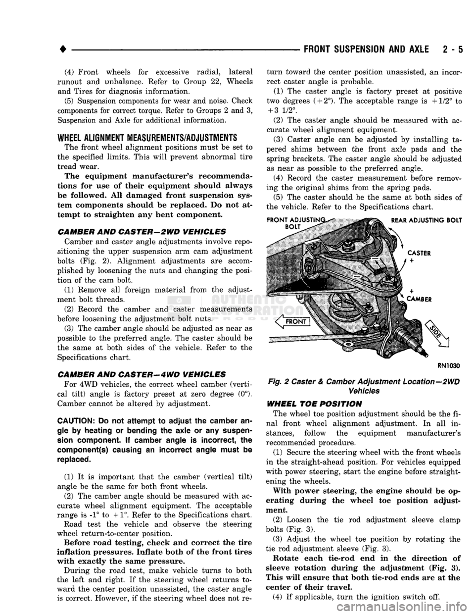
CAMBER AND CASTER-2WD VEHICLES Camber and caster angle adjustments involve repo
sitioning the upper suspension arm cam adjustment
bolts (Fig. 2). Alignment adjustments are accom
plished by loosening the nuts and changing the posi
tion of the cam bolt.
(1) Remove all foreign material from the adjust
ment bolt threads.
(2) Record the camber and caster measurements
before loosening the adjustment bolt nuts.
(3) The camber angle should be adjusted as near as
possible to the preferred angle. The caster should be
the same at both sides of the vehicle. Refer to the Specifications chart.
CAMBER AND CASTER—4WD VEHICLES For 4WD vehicles, the correct wheel camber (verti
cal tilt) angle is factory preset at zero degree (0°).
Camber cannot be altered by adjustment.
CAUTION: Do not attempt to
adjust
the
camber
an
gle by
heating
or bending the axle or any
suspen
sion
component. If camber angle is
incorrect,
the
component(s)
causing
an
incorrect
angle must be replaced.
(1) It is important that the camber (vertical tilt)
angle be the same for both front wheels.
(2) The camber angle should be measured with ac
curate wheel alignment equipment. The acceptable
range is -1° to +1°. Refer to the Specifications chart.
Road test the vehicle and observe the steering
wheel return-to-center position. Before road testing,
check
and
correct
the tire
inflation pressures. Inflate
both
of the front tires
with exactly the
same
pressure.
During the road test, make vehicle turns to both
the left and right. If the steering wheel returns to
ward the center position unassisted, the caster angle is correct. However, if the steering wheel does not re turn toward the center position unassisted, an incor
rect caster angle is probable.
(1) The caster angle is factory preset at positive
two degrees
(
+
2°).
The acceptable range is +1/2° to +
3
1/2°.
(2) The caster angle should be measured with ac
curate wheel alignment equipment.
(3) Caster angle can be adjusted by installing ta
pered shims between the front axle pads and the spring brackets. The caster angle should be adjusted
as near as possible to the preferred angle.
(4) Record the caster measurement before remov
ing the original shims from the spring pads.
(5) The caster should be the same at both sides of
the vehicle. Refer to the Specifications chart.
RN1030
Fig.
2 Caster &
Camber
Adjustment Location—2WD
Vehicles
WHEEL TOE POSITION The wheel toe position adjustment should be the fi
nal front wheel alignment adjustment. In all in stances, follow the equipment manufacturer's
recommended procedure.
(1) Secure the steering wheel with the front wheels
in the straight-ahead position. For vehicles equipped
with power steering, start the engine before straight ening the wheels.
With power steering, the engine should be op
erating during the wheel toe position adjust
ment.
(2) Loosen the tie rod adjustment sleeve clamp
bolts (Fig. 3).
(3) Adjust the wheel toe position by rotating the
tie rod adjustment sleeve (Fig. 3). Rotate each tie-rod end in the direction of
sleeve rotation during the adjustment (Fig. 3).
This will ensure that both tie-rod ends are at the center of their travel.
(4) If applicable, turn the ignition switch off.
Page 812 of 1502
FRAME
AND
BUMPERS
13 - 25
FUNCTION
The frame is the foundation and the structural cen
ter of the vehicle. The primary function of a frame is
to provide support and attachment locations: • For all the chassis/drivetrain components
• For the cab/body
• For the vehicle payload While limiting deflections and twisting of the
frame members. The frame maintains the correct relationship and
alignment of the powertrain. This relationship and
alignment ensures normal operation of the attached
units.
CONSTRUCTION MATERIAL High-strength, carbon steel with a minimum yield
strength of 32,000 psi is used to construct frame side
rails.
A frame made of 32,000 psi minimum yield
strength steel has, in reality, a range of 32,000 to
44,000 psi yield strength.
For 4WD vehicle applications, the frame side rails
reinforcements are constructed of the same high- strength, carbon steel as the side rails.
BENDING RESISTANCE A frame reacts to its load and the road surface de
viations by deflecting and twisting. The primary de
flecting frame members are the side rails. Resistance
to frame twist is provided by the crossmembers.
FRAME
INSPECTION/MEASUREMENTS
INSPECTION Inspect the frame members for visible damage and
metal deformations. Inspect all riveted, bolted and
welded connections for looseness and/or missing hardware. All damaged areas must be repaired and/or the
frame members replaced, as necessary.
MEASUREMENTS Measure the frame for mis-alignment with the cab/
body and cargo box attached to the frame. Figures 7, 8, 9 provide the frame alignment reference dimen
sions.
The following information applies to all measure
ments.
(1) Place the vehicle on a level surface.
(2) If the vehicle is loaded, verify the vehicle does
not exceed the gross vehicle weight rating (GVWR).
Verify the load is distributed in the vehicle as evenly as possible. For better measurement results, remove
the cargo/payload from the vehicle.
(3) Measure the tire inflation pressures. Adjust as
necessary.
HORIZONTAL/DIAGONAL
FRAME MEASUREMENTS
Determine the frame horizontal, according to the
following procedure.
(1) Select several reference points along one frame
side rail, preferably at the crossmember junctions.
(2) Transfer these reference points to the surface/
floor. Paper sheets can be attached to the surface be low the reference points.
(3) Locate the same reference points on the other
frame side rail. Transfer them to the surface/floor.
(4) Move the vehicle away. Measure between all
the reference points diagonally from and parallel to
the side rails (Fig. 10). The corresponding measure ments should not differ by more than 6 mm (1/4 in).
(5)
Measure the distance between the two front
reference points. Measure the distance between the
two rear reference points. Divide each distance in
half and indicate the two half-way points on the sur
face/floor. Designate the front point as 1 and the rear
point as 2 (Fig. 10).
(6) Place a chalk-line between points 1 and 2 (Fig.
10) and snap the string.
(7) Determine how close the center line is to the
diagonal intersection points in Figure 10.
(8) The marks on the floor will show the amount of
frame misalignment.
(9) The reference point transferred from one side
rail should be within 3 mm (1/8 in) of the opposite
reference point.
(10) Frame bow to the side should not exceed 3
mm per 2540 mm (1/8 inch per 100 inches) in frame
length.
(11) The overall width of the frame should not
vary more than 3 mm (1/8 in). (12) Repeat steps (1) through (11) after straighten
ing the frame.
Refer to Figures 7, 8, and 9 for frame horizon
tal alignment reference dimensions.
TWIST
AND PARALLEL FRAME MEASUREMENTS
Determine the amount of frame twist using the fol
lowing procedure.
(1) Mark the vertical reference points under the
frame side rails at 305-mm (12-in) intervals. Start at
the rear frame crossmember.
(2) Measure the distance up from a level surface/
floor to each corresponding reference point. (3) The distance to a reference point under one
side rail should be a maximum of 3 mm (1/8 in)
dif
ference than the opposite side rail.
Refer to Figures 7, 8 and 9 for frame vertical
alignment reference dimensions.
Page 1370 of 1502
•
WHEELS
AND
TIRES
22 - 1
CONTENTS
page page
TIRES
1
VEHICLE VIBRATION
11
TORQUE SPECIFICATIONS
13
WHEELS
6
TIRES INDEX
page
Cleaning
of
Tires
2
General
Information
1
Pressure
Gauges
. 2
Repairing Leaks
3
Replacement Tires
2
GENERAL
INFORMATION
Tires are designed for each specific vehicle. They
provide the best overall performance for normal op eration. The ride and handling characteristics match
the vehicle's requirements. With proper care they
will give excellent reliability, traction, skid resis
tance, and tread life. These tires have specific load carrying capacities. When correctly inflated, they
will operate properly.
Tires used in cool climates, and with light loads
will have a longer life than tires used in hot climates
with heavy loads. Abrasive road surfaces will accel erate tire wear.
Driving habits have more effect on tire life than
any other factor. Careful drivers will obtain much
greater mileage than careless drivers.
Driving habits that shorten the life of any tire;
• Rapid acceleration and deceleration
• Severe application of brakes • High-speed driving
• Taking turns at excessive speeds
• Striking curbs and other obstacles It is very important to follow the tire rotation in
terval
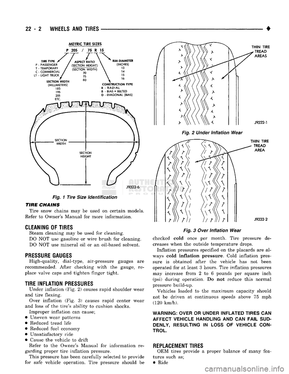
IDENTIFICATION Tire type, size, aspect ratio and speed rating are
encoded in the letters and numbers imprinted on the
side wall of the tire. Refer to the chart to decipher
the tire identification code (Fig. 1). Performance tires will have a speed rating letter
after the aspect ratio number. The speed rating is
page
Rotation
. 3
Tire
Inflation
Pressures
2
Tire
Noise
or
Vibration
4
Tire
Wear
Patterns
4
Tread Wear
Indicators
3
not always printed on the tire side wall. The letter S
indicates that the tire is speed rated up to 112 mph.
• Q up to 100 mph
• T up to 118 mph
• U up to 124 mph
• H up to 130 mph
• V up to 149 mph
• Z more than 149 mph (consult the tire manufac
turer for the specific speed rating)
An All Season type tire will have either M + S, M
& S or M—S (indicating mud and snow traction) im
printed on the side wall.
RADIAL-PLY TIRES Radial-ply tires improve handling, tread life, ride
quality and decrease rolling resistance. Radial-ply tires must always be used in sets of
four. Under no circumstances should they be used on
the front only. They may be mixed with temporary spare tires when necessary, but reduced speeds are
recommended.
Radial-ply tires have the same load-carrying capac
ity as other types of tires of the same size. They use
the same recommended inflation pressures.
SPARE TIRE (TEMPORARY) The compact spare tire is designed for emergency
use only. The original tire should be repaired and re
installed at the first opportunity. Refer to Owner's
Manual for complete details.
WHEELS
AND
TIRES
Page 1371 of 1502
22 - 2
WHEELS
AND
TIRES
•
METRIC
TIRE
SIZES
P
205 / 75 I 15
J9322-6
Fig.
1
Tire
Size
identification
TIRE
CHAINS
Tire snow chains may be used on certain models.
Refer to Owner's Manual for more information.
CLEANING
OF
TIRES
Steam cleaning may be used for cleaning.
DO NOT use gasoline or wire brush for cleaning.
DO NOT use mineral oil or an oil-based solvent.
PRESSURE GAUGES
High-quality, dial-type, air-pressure gauges are
recommended. After checking with the gauge, re
place valve caps and tighten finger tight.
TIRE
INFLATION
PRESSURES
Under inflation (Fig. 2) causes rapid shoulder wear
and tire flexing. Over inflation (Fig. 3) causes rapid center wear
and loss of the tire's ability to cushion shocks. Improper inflation can cause;
• Uneven wear patterns
• Reduced tread life
• Reduced fuel economy
• Unsatisfactory ride
• Cause the vehicle to drift Refer to the Owner's Manual for information re
garding proper tire inflation pressure. This pressure has been carefully selected to provide
for safe vehicle operation. Tire pressure should be
Fig.
2
Under
infiation
Wear
Fig.
3
Over
Infiation
Wear
checked cold once per month. Tire pressure de creases when the outside temperature drops.
Inflation pressures specified on the placards are al
ways cold
inflation
pressure. Cold inflation pres sure is obtained after the vehicle has not been
operated for at least 3 hours. Tire inflation pressures may increase from 2 to 6 pounds per square inch (psi) during operation. Do not reduce this normal
pressure build-up.
Vehicles loaded to the maximum capacity should
not be driven at continuous speeds above 75 mph (120 km/h).
WARNING: OVER
OR
UNDER INFLATED TIRES
CAN
AFFECT VEHICLE HANDLING
AND CAN
FAIL
SUD DENLY, RESULTING
IN
LOSS
OF
VEHICLE CON
TROL
REPLACEMENT TIRES
OEM tires provide a proper balance of many fea
tures such as; • Ride
Page 1373 of 1502
22 - 4
WHEELS
AND
TIRES
• puncture is in the tread area (Fig. 7). If outside the
tread area the tire should be replaced.
J8922-6
Fig.
7
Tire
Repair Area
Deflate tire completely before dismounting tire
from the wheel. Use lubrication such as a mild soap solution when dismounting or mounting tire. Use
tools free of burrs or sharp edges.
Before mounting tire on wheel, make sure all rust
scale is removed from the rim. Repaint or seal if nec
essary.
TIRE NOISE
OR
VIBRATION
The radial-ply tire on your vehicle is more sensi
tive to improper mounting, or imbalance. To determine if tires are the cause of vibration,
drive the vehicle over a smooth road at different speeds. Note the effect of acceleration and decelera
tion on noise level. Differential and exhaust noise
will change in intensity as speed varies. Tire noise
will usually remain constant.
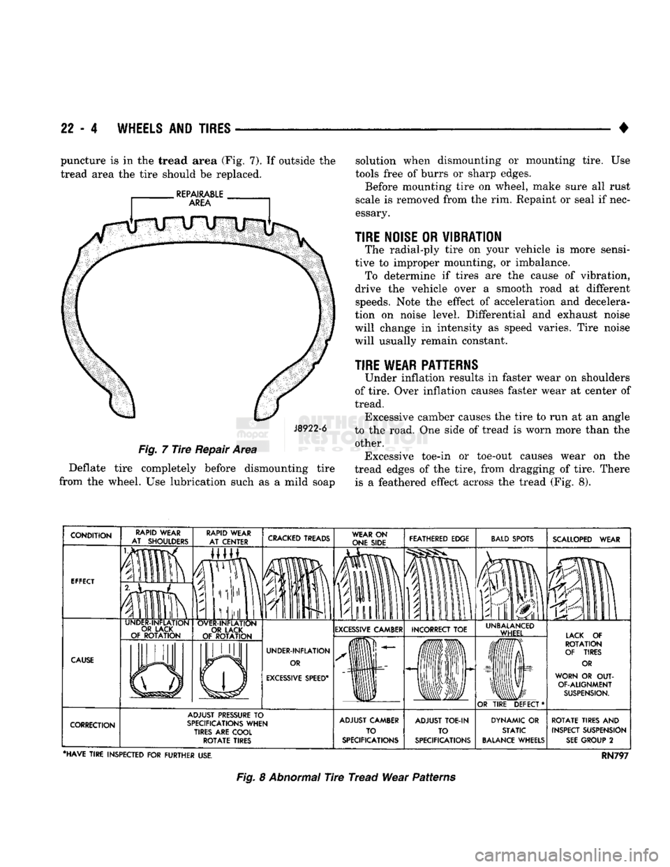
TIRE WEAR PATTERNS
Under inflation results in faster wear on shoulders
of tire. Over inflation causes faster wear at center of
tread. Excessive camber causes the tire to run at an angle
to the road. One side of tread is worn more than the other. Excessive toe-in or toe-out causes wear on the
tread edges of the tire, from dragging of tire. There is a feathered effect across the tread (Fig. 8).
CRACKED
TREADS
WEAR
ON
ONE SIDE FEATHERED EDGE
BALD
SPOTS
IP
fa
SCALLOPED
WEAR
EXCESSIVE
CAMBER INCORRECT
TOE
EXCESSIVE
SPEED*
UNBALANCED
WHEEL LACK
OF
ROTATION
OF TIRES
OR
WORN
OR OUT-
OF-ALIGNMENT
SUSPENSION.
OR
TIRE
DEFECT* ADJUST
PRESSURE
TO
SPECIFICATIONS
WHEN
TIRES ARE COOL
ROTATE
TIRES ADJUST CAMBER
TO
SPECIFICATIONS ADJUST
TOE-IN
TO
SPECIFICATIONS DYNAMIC
OR
STATIC
BALANCE
WHEELS
ROTATE
TIRES
AND
INSPECT SUSPENSION
SEE
GROUP
2
•HAVE
TIRE
INSPECTED
FOR
FURTHER
USE.
RN797
Fig.
8 Abnormal Tire Tread Wear Patterns