lug pattern DODGE TRUCK 1993 Service Repair Manual
[x] Cancel search | Manufacturer: DODGE, Model Year: 1993, Model line: TRUCK, Model: DODGE TRUCK 1993Pages: 1502, PDF Size: 80.97 MB
Page 239 of 1502
5
- 52
BRAKES
•
BRAKE
DRUM
REMOVAL
(1) Raise and support vehicle.
(2) Remove wheel and tire assembly.
(3) Remove axle shaft nuts, washers and cones.
Strike axle shaft in center with copper or dead blow
hammer to loosen retaining cones.
(4) Remove axle shaft.
(5) Remove outer hub nut.
(6)
Straighten and remove lock washer.
(7) Remove inner nut and bearing.
(8) Remove drum. If drum is difficult to remove,
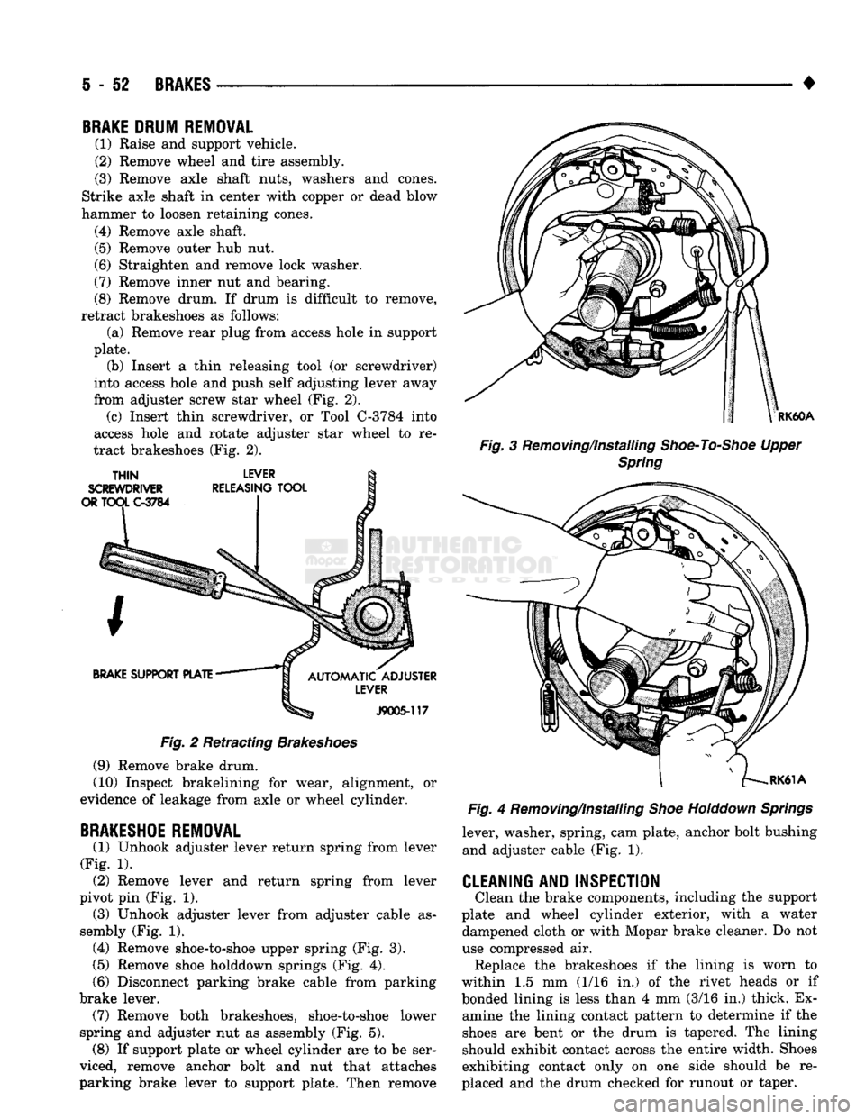
retract brakeshoes as follows: (a) Remove rear plug from access hole in support
plate. (b) Insert a thin releasing tool (or screwdriver)
into access hole and push self adjusting lever away
from adjuster screw star wheel (Fig. 2). (c) Insert thin screwdriver, or Tool C-3784 into
access hole and rotate adjuster star wheel to re
tract brakeshoes (Fig. 2).
Fig.
2 Retracting
Brakeshoes
(9) Remove brake drum.
(10) Inspect brakelining for wear, alignment, or
evidence of leakage from axle or wheel cylinder.
BRAKESHOE
REMOVAL
(1) Unhook adjuster lever return spring from lever
(Fig. 1). (2) Remove lever and return spring from lever
pivot pin (Fig. 1). (3) Unhook adjuster lever from adjuster cable as
sembly (Fig. 1). (4) Remove shoe-to-shoe upper spring (Fig. 3).
(5)
Remove shoe holddown springs (Fig. 4).
(6)
Disconnect parking brake cable from parking
brake lever. (7) Remove both brakeshoes, shoe-to-shoe lower
spring and adjuster nut as assembly (Fig. 5). (8) If support plate or wheel cylinder are to be ser
viced, remove anchor bolt and nut that attaches
parking brake lever to support plate. Then remove
RK60A
Fig.
3 Removing/Installing
Shoe-To-Shoe
Upper
Spring
Fig.
4 Removing/Installing
Shoe
Holddown
Springs
lever, washer, spring, cam plate, anchor bolt bushing and adjuster cable (Fig. 1).
CLEANING AND INSPECTION
Clean the brake components, including the support
plate and wheel cylinder exterior, with a water dampened cloth or with Mopar brake cleaner. Do not
use compressed air. Replace the brakeshoes if the lining is worn to
within 1.5 mm (1/16 in.) of the rivet heads or if
bonded lining is less than 4 mm (3/16 in.) thick. Ex amine the lining contact pattern to determine if the
shoes are bent or the drum is tapered. The lining
should exhibit contact across the entire width. Shoes
exhibiting contact only on one side should be re
placed and the drum checked for runout or taper.
Page 1002 of 1502
•
TRANSMISSION
AND
TRANSFER
CASE
21 - 1
CONTENTS
page
AUTOMATIC
TRANSMISSI0N-32RH/36RH/
37RH/42RH/46RH
73
G360
MANUAL
TRANSMISSION
46
6360
TRANSMISSION
OVERHAUL
..........
53
NP2Q5
TRANSFER
CASE
................
342
page
NP241
TRANSFER
CASE
350
NV4500 MANUAL
TRANSMISSION
1
NV4500
TRANSMISSION
OVERHAUL
.........
6
TRANSMISSION/TRANSFER
CASE
SPECIFICATIONS
.....................
364
NV4300
MANUAL TRANSMISSION
INDEX
page
Gear Ratios
1
General
Information
1
Recommended
Lubricant—Capacity—Fill
Level
... 1
Shift
Pattern
1
Transmission Diagnosis
2
page
Transmission
Identification
1
Transmission
Installation—2-Wheel
Drive
4
Transmission
Installation—4-Wheel
Drive
........
5
Transmission
Removal—2-Wheel
Drive
3
Transmission
Removal—4-Wheel
Drive
4
GENERAL
INFORMATION The NV4500
is a
five-speed, constant mesh manual
transmission (Fig.
1). All
gear ranges including
re
verse
are
synchronized. Fifth gear
is an
overdrive
range with
a
ratio
of
0.74:1.
The transmission has
a
cast iron gear case and aluminum shift cover. The NV4500
is a
top loader style transmission. The
shift lever
is
located
in the
shift cover and operates
the shift forks and rails directly. The shift forks and
rails
are all
located within
the
aluminum cover
which
is
bolted
to
the top
of
the gear case.
A reverse gear inhibitor mechanism prevents
re
verse gear engagement when shifting into forward
gear ranges. The inhibitor mechanism
is
located
in
the shift cover.
Tapered roller bearings support
the
drive gear,
mainshaft
and
countershaft
in the
gear case. Pilot
roller bearings
in
the drive gear hub support the for
ward end
of
the mainshaft. The mainshaft gears
are
all supported
on
caged type roller bearings. Drive
gear thrust reaction
is
controlled
by a
needle type
thrust bearing. The bearing
is
located
at
the forward
end
of
the mainshaft.
TRANSMISSION
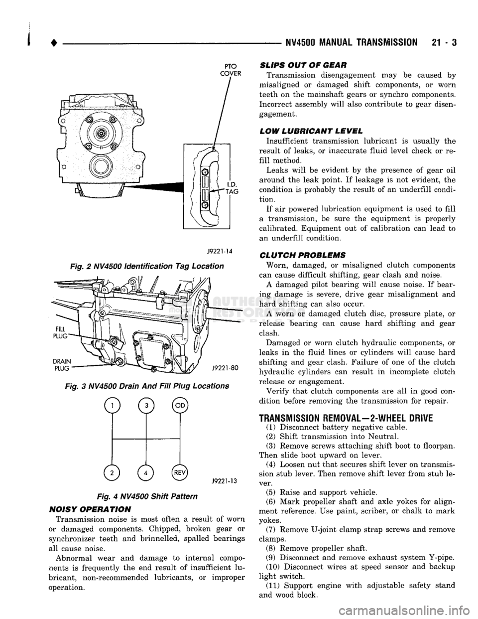
IDENTIFICATION The NV4500 transmission identification
tag is at
tached
to
the driver side PTO cover (Fig.
2).
The
tag
provides
the
transmission model number,
build date and part number.
Be
sure
to
reinstall
the
I.D.
tag if
removed during service. The information
on the tag
is
essential
to
correct parts ordering.
RECOMMENDED
LUBRICANT-CAPACITY-FILL
LEVEL
Recommended lubricant
for
the NV4500
is
Castrol
Syntorq. This
is a
SAE 75W-90 synthetic gear lubri
cant with
an
API grade rating
of
GL
4.
Syntorq
is
the only lubricant recommended
for
use
in
NV4500 transmissions. Dry fill lubricant capacity
is
approximately 3.78
li
ters
(8
pints). Correct lubricant fill level
is to
the bottom edge
of
the fill plug hole (Fig. 3). Check fill level only when
the transmission
is
level.
GEAR
RATIOS
NV4500 gear ratios are:
First gear:
5.61:1
Second gear: 3.04:1
Third gear:
1.67:1
Fourth gear:
1.00:1
Fifth gear: 0.74:1
Reverse gear:
5.61:1
SHIFT
PATTERN
The NV4500 shift pattern
is in a
modified
H
pat
tern (Fig. 4). Overdrive fifth and reverse gears are
in
line and outboard of the first through fourth gear po
sitions.
TRANSMISSION
AND
TRANSFER
CASE
Page 1004 of 1502
•
NV4500 MANUAL
TRANSMISSION
21 - 3
PTO
COVER
J9221-14
Fig. 2 NV4500 identification Tag Location
DRAIN
PLUG
J9221-80
Fig. 3 NV4500 Drain And Fill Plug Locations
o
0 ©
0 0©
J9221-13
Fig. 4 NV4500 Shitt Pattern
NOISY OPERATION Transmission noise is most often a result of worn
or damaged components. Chipped, broken gear or
synchronizer teeth and brinnelled, spalled bearings
all cause noise.
Abnormal wear and damage to internal compo
nents is frequently the end result of insufficient lu
bricant, non-recommended lubricants, or improper operation.
SLIPS
OUT OF
GEAR
Transmission disengagement may be caused by
misaligned or damaged shift components, or worn
teeth on the mainshaft gears or synchro components. Incorrect assembly will also contribute to gear disengagement.
LOW LUBRICANT LEWEL
Insufficient transmission lubricant is usually the
result of leaks, or inaccurate fluid level check or re
fill method.
Leaks will be evident by the presence of gear oil
around the leak point. If leakage is not evident, the
condition is probably the result of an underfill condi
tion.
If air powered lubrication equipment is used to fill
a transmission, be sure the equipment is properly
calibrated. Equipment out of calibration can lead to
an underfill condition.
CLUTCH
PROBLEMS
Worn, damaged, or misaligned clutch components
can cause difficult shifting, gear clash and noise.
A damaged pilot bearing will cause noise. If bear
ing damage is severe, drive gear misalignment and
hard shifting can also occur.
A worn or damaged clutch disc, pressure plate, or
release bearing can cause hard shifting and gear clash.
Damaged or worn clutch hydraulic components, or
leaks in the fluid lines or cylinders will cause hard shifting and gear clash. Failure of one of the clutch
hydraulic cylinders can result in incomplete clutch release or engagement.
Verify that clutch components are all in good con
dition before removing the transmission for repair.
TRANSMISSION
REMOVAL—2-WHEEL DRIVE
(1) Disconnect battery negative cable. (2) Shift transmission into Neutral.
(3) Remove screws attaching shift boot to floorpan.
Then slide boot upward on lever. (4) Loosen nut that secures shift lever on transmis
sion stub lever. Then remove shift lever from stub le
ver. (5) Raise and support vehicle.
(6) Mark propeller shaft and axle yokes for align
ment reference. Use paint, scriber, or chalk to mark
yokes.
(7) Remove U-joint clamp strap screws and remove
clamps. (8) Remove propeller shaft.
(9) Disconnect and remove exhaust system Y-pipe.
(10) Disconnect wires at speed sensor and backup
light switch. (11) Support engine with adjustable safety stand
and wood block.
Page 1152 of 1502
•
AUTOMATIC
TRANSMISSION
REMOVAL
AND
INSTALLATION
21 - 151
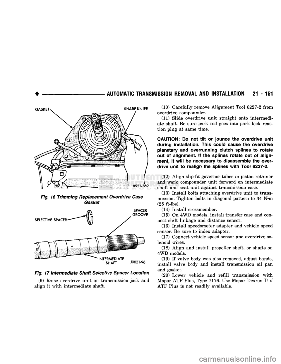
Fig.
17
Intermediate
Shaft Selective
Spacer
Location (9) Raise overdrive unit on transmission jack and
align it with intermediate shaft. (10) Carefully remove Alignment Tool 6227-2 from
overdrive compounder.
(11) Slide overdrive unit straight onto intermedi
ate shaft. Be sure park rod goes into park lock reac
tion plug at same time.
CAUTION:
Do not tilt or
jounce
the
overdrive unit
during installation. This could cause
the
overdrive planetary
and
overrunning clutch splines
to
rotate
out
of
alignment.
If the
splines
rotate
out of
align ment,
it
will
be
necessary
to
disassemble
the
over
drive unit
to
realign
the
splines
with
Tool
6227-2.
(12) Align slip-fit governor tubes in piston retainer
and work compounder unit forward on intermediate
shaft and seat unit against transmission case.
(13) Install bolts attaching overdrive unit to trans
mission. Tighten bolts in diagonal pattern to 34 N»m (25 ft-lbs).
(14) Install crossmember.
(15) On 4WD models, install transfer case and con
nect shift linkage and distance sensor. (16) Install speedometer adapter and vehicle speed
sensor. Be sure to index adapter.
(17) Connect vehicle speed sensor and overdrive so
lenoid wires.
(18) Align and install propeller shaft, or shafts on
4WD models. (19) If valve body was also removed, adjust bands,
install valve body and install transmission oil pan and gasket.
(20) Lower vehicle and refill transmission with
Mopar ATF Plus, Type 7176. Use Mopar Dexron II if
ATF Plus is not readily available.
Page 1183 of 1502
21
- 182
TRANSMISSION OVERHAUL—32RH
• VAL VE
BODY
ASSEMBL
Y
CAUTION:
Do not
force
the valves or plugs
into
place
during
reassembly. If the valve body
bores,
valves
and plugs are
free
of
distortion
or burrs, the
valve body components should all slide
into
place
easily. In
addition,
do not
overtighten
the
transfer
plate
and valve body
screws
during
reassembly.
Overtightening
can
distort
the valve body
resulting
in valve sticking,
cross
leakage and
unsatisfactory
operation. Tighten valve body
screws
to recom mended
torque
only.
(1) Lubricate valve body bores, valves and plugs
with transmission fluid.
(2) Insert rear clutch and rear servo check balls in
transfer plate (Fig. 100).
(3) Install filter screen in separator plate (Fig.
100).
(4) Align and install separator plate on transfer
plate. Verify check ball position before installing sep arator plate on transfer plate.
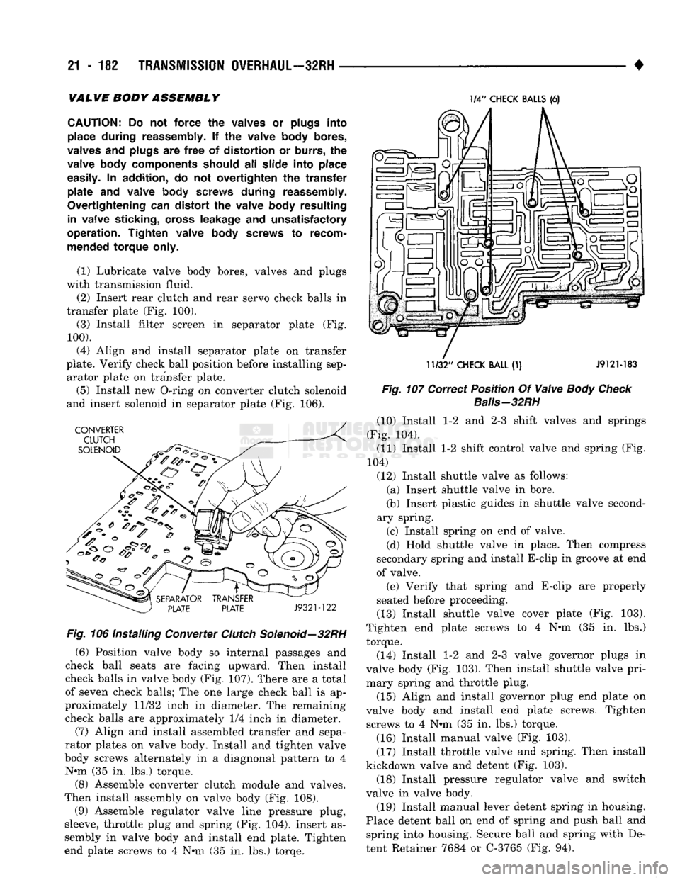
(5) Install new O-ring on converter clutch solenoid
and insert solenoid in separator plate (Fig. 106). Fig. 106
Installing
Converter
Clutch
Solenoid—32RH
(6) Position valve body so internal passages and
check ball seats are facing upward. Then install
check balls in valve body (Fig. 107). There are a total
of seven check balls; The one large check ball is ap
proximately 11/32 inch in diameter. The remaining
check balls are approximately 1/4 inch in diameter.
(7) Align and install assembled transfer and sepa
rator plates on valve body. Install and tighten valve
body screws alternately in a diagnonal pattern to 4 N»m (35 in. lbs.) torque.
(8) Assemble converter clutch module and valves.
Then install assembly on valve body (Fig. 108).
(9) Assemble regulator valve line pressure plug,
sleeve, throttle plug and spring (Fig. 104). Insert as
sembly in valve body and install end plate. Tighten
end plate screws to 4 N»m (35 in. lbs.) torqe. 1/4"
CHECK
BALLS
(6)
11/32"
CHECK
BALL
(1) J912M83
Fig. 107
Correct
Position
Of
Valve
Body Check
Baiis-32RH
(10) Install 1-2 and 2-3 shift valves and springs
(Fig. 104).
(11) Install 1-2 shift control valve and spring (Fig.
104)
(12) Install shuttle valve as follows: (a) Insert shuttle valve in bore.
(b) Insert plastic guides in shuttle valve second
ary spring.
(c) Install spring on end of valve.
(d) Hold shuttle valve in place. Then compress
secondary spring and install E-clip in groove at end
of valve. (e) Verify that spring and E-clip are properly
seated before proceeding.
(13) Install shuttle valve cover plate (Fig. 103).
Tighten end plate screws to 4 N»m (35 in. lbs.)
torque.
(14) Install 1-2 and 2-3 valve governor plugs in
valve body (Fig. 103). Then install shuttle valve pri
mary spring and throttle plug.
(15) Align and install governor plug end plate on
valve body and install end plate screws. Tighten screws to 4 N*m (35 in. lbs.) torque.
(16) Install manual valve (Fig. 103).
(17) Install throttle valve and spring. Then install
kickdown valve and detent (Fig. 103).
(18) Install pressure regulator valve and switch
valve in valve body.
(19) Install manual lever detent spring in housing.
Place detent ball on end of spring and push ball and spring into housing. Secure ball and spring with De
tent Retainer 7684 or C-3765 (Fig. 94).
Page 1222 of 1502
•
TRANSMISSION
OVERHAUL—36RH/37RH
21 - 221 (3) Align and install separator plate on transfer
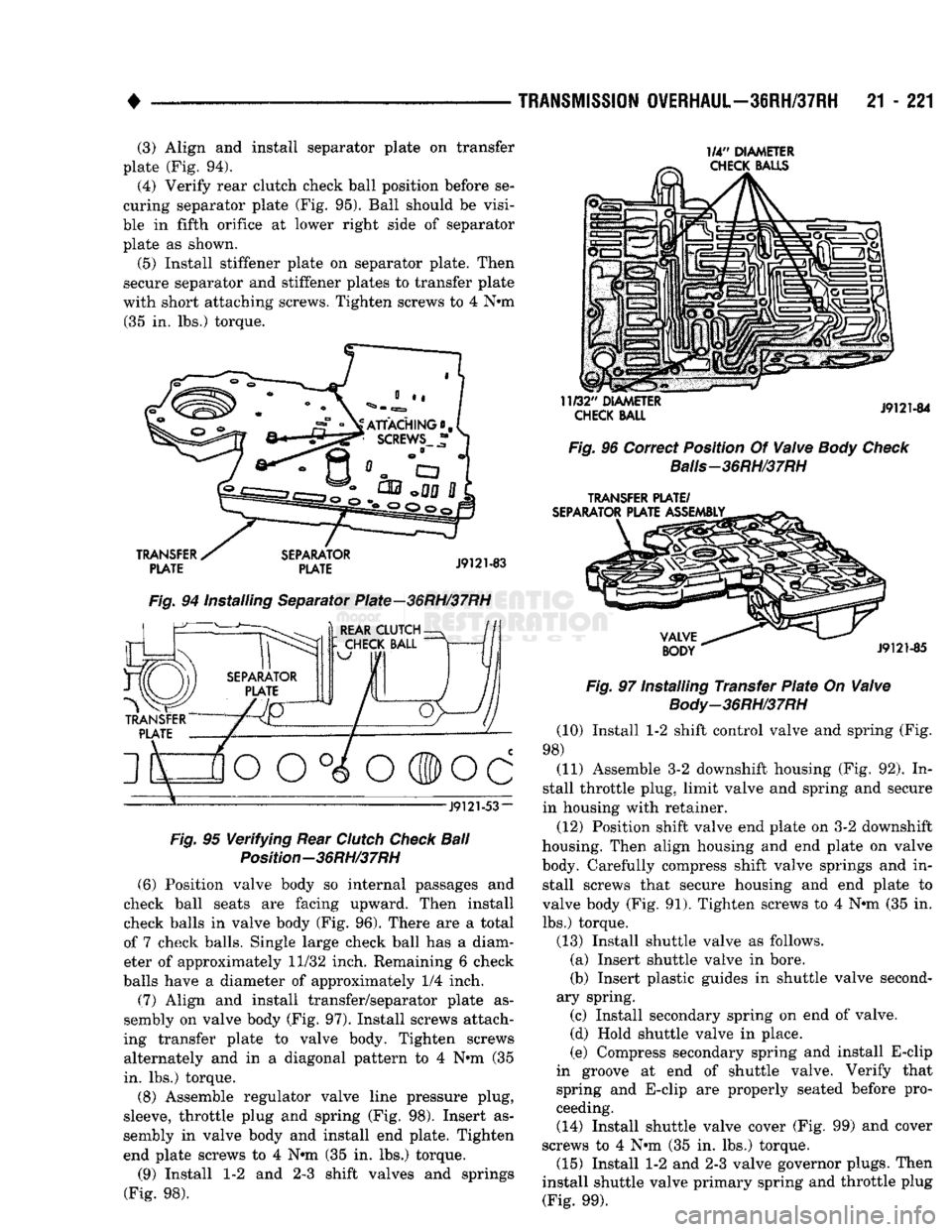
plate (Fig. 94). (4) Verify rear clutch check ball position before se
curing separator plate (Fig. 95). Ball should be visi
ble in fifth orifice at lower right side of separator plate as shown.
(5) Install stiffener plate on separator plate. Then
secure separator and stiffener plates to transfer plate
with short attaching screws. Tighten screws to 4 Nnn (35 in. lbs.) torque. 1/4"
DIAMETER
CHECK
BALLS
TRANSFER
PLATE
SEPARATOR
PLATE
J9121-83
Fig.
94 Installing Separator Plate—36RH/37RH f^-^. )
REAR CLUTCH-
J9121-53-
Fig.
95
Verifying
Rear
Clutch
Check
Ball
Position-36RH/37RH (6) Position valve body so internal passages and
check ball seats are facing upward. Then install
check balls in valve body (Fig. 96). There are a total
of 7 check balls. Single large check ball has a diam eter of approximately 11/32 inch. Remaining 6 check
balls have a diameter of approximately 1/4 inch.
(7) Align and install transfer/separator plate as
sembly on valve body (Fig. 97). Install screws attach
ing transfer plate to valve body. Tighten screws alternately and in a diagonal pattern to 4 Nnn (35
in. lbs.) torque.
(8) Assemble regulator valve line pressure plug,
sleeve, throttle plug and spring (Fig. 98). Insert as
sembly in valve body and install end plate. Tighten
end plate screws to 4 Nnn (35 in. lbs.) torque.
(9) Install 1-2 and 2-3 shift valves and springs
(Fig. 98).
11/32"
DIAMETER
CHECK
BALL
J9121-84
Fig.
96 Correct Position Of
Valve
Body Check
Balis-36RH/37RH
TRANSFER
PLATE/
SEPARATOR
PLATE ASSEMBLY
VALVE
BODY
J9121-85
Fig.
97 Installing Transfer
Plate
On
Valve
Body-36RH/37RH
(10) Install 1-2 shift control valve and spring (Fig.
98) (11) Assemble 3-2 downshift housing (Fig. 92). In
stall throttle plug, limit valve and spring and secure
in housing with retainer.
(12) Position shift valve end plate on 3-2 downshift
housing. Then align housing and end plate on valve
body. Carefully compress shift valve springs and in stall screws that secure housing and end plate to
valve body (Fig. 91). Tighten screws to 4 Nnn (35 in.
lbs.) torque.
(13) Install shuttle valve as follows. (a) Insert shuttle valve in bore.
(b) Insert plastic guides in shuttle valve second
ary spring. (c) Install secondary spring on end of valve.
(d) Hold shuttle valve in place.
(e) Compress secondary spring and install E-clip
in groove at end of shuttle valve. Verify that
spring and E-clip are properly seated before pro
ceeding. (14) Install shuttle valve cover (Fig. 99) and cover
screws to 4 Nnn (35 in. lbs.) torque. (15) Install 1-2 and 2-3 valve governor plugs. Then
install shuttle valve primary spring and throttle plug (Fig. 99).
Page 1276 of 1502
•
BAND BAND
Fig.
152 Front
Band
Linkage
Installation—42RH
SEAL
RINGS
J9121-194
Fig.
153 Reaction Shaft
Support
Seal
Rings
And Front
Clutch
Thrust
Washer
Position—42RH
work it into front clutch hub and case by hand. Then
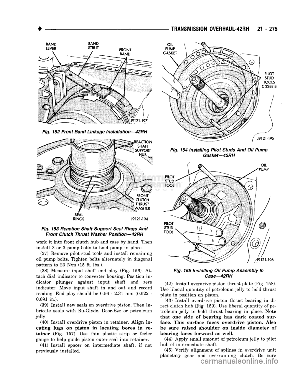
install 2 or 3 pump bolts to hold pump in place. (37) Remove pilot stud tools arid install remaining
oil pump bolts. Tighten bolts alternately in diagonal
pattern to 20 N*m (15 ft. lbs.).
(38) Measure input shaft end play (Fig. 156). At
tach dial indicator to converter housing. Position in dicator plunger against input shaft and zero indicator. Move input shaft in and out and record
reading. End play should be 0.56 - 2.31 mm (0.022 - 0.091 in.).
(39) Install new seals on overdrive piston. Then lu
bricate seals with Ru-Glyde, Door-Eze or petroleum
jelly. (40) Install overdrive piston in retainer. Align lo
cating lugs on piston in locating bores in re
tainer (Fig. 157). Use thin plastic strip or feeler gauge to help guide piston outer seal into retainer. (41) Install spacer on intermediate shaft, if not
previously installed.
TRANSMISSION
0VERHAUL-42RH
21 - 275
Fig.
154 Installing Pilot
Studs
And Oil
Pump
Gasket-42RH
Fig.
155 Installing Oil
Pump
Assembly
In
Case—42RH
(42) Install overdrive piston thrust plate (Fig. 158).
Use liberal quantity of petroleum jelly to hold thrust
plate in position on piston. (43) Install overdrive piston thrust bearing in di
rect clutch hub (Fig. 159). Use liberal quantity of pe
troleum jelly to hold thrust bearing in place. Note
that one side of bearing has dark coated sur
face. This surface faces overdrive piston. Also
be sure raised shoulder on inside diameter of
bearing faces forward as well.
(44) Apply small amount of petroleum jelly to pilot
hub of intermediate shaft.
(45) Verify alignment of splines in overdrive unit
planetary gear and overrunning clutch. Be sure
Page 1375 of 1502
22 - e
WHEELS
AND
TIRES
• WHEELS
GENERAL
INFORMATION
Original equipment wheels are designed for all
loads up to the specified Maximum Vehicle Capacity. All models use steel or cast aluminum drop center
wheels. The safety rim wheel (Fig. 1) has raised sec
tions between the rim flanges and the rim well.
S
J9022-3
Fig.
1
Wheel
Safety Rim Initial inflation of the tire forces the bead over
these raised sections. In case of tire failure, the
raised sections hold the tire in position on the wheel
until the vehicle can be brought to a safe stop.
Cast aluminum wheels require special balance
weights and alignment equipment.
DUAL
REAR
WHEELS
Ram Truck Models
D-350
and
W-350
equipped
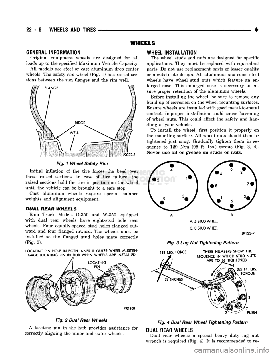
with dual rear wheels have eight-stud hole rear
wheels. Four equally-spaced stud holes flanged out
ward and four flanged inward. The wheels must be
installed so the flanged stud holes mate correctly (Fig. 2).
LOCATING PIN HOLE
IN
BOTH INNER
&
OUTER WHEEL
MUST
EN
GAGE
LOCATING PIN
IN
HUB WHEN WHEELS ARE INSTALLED.
PR1100
Fig.
2
Dual
Rear
Wheels
A locating pin in the hub provides assistance for
correctly aligning the inner and outer wheels.
WHEEL
INSTALLATION
The wheel studs and nuts are designed for specific
applications. They must be replaced with equivalent
parts.
Do not use replacement parts of lesser quality or a substitute design. All aluminum and some steel
wheels have wheel stud nuts which feature an en larged nose. This enlarged nose is necessary to en
sure proper retention of the aluminum wheels. Before installing the wheel, be sure to remove any
build up of corrosion on the wheel mounting surfaces. Ensure wheels are installed with good metal-to-metal contact. Improper installation could cause loosening
of wheel nuts. This could affect the safety and han
dling of your vehicle. To install the wheel, first position it properly on
the mounting surface. All wheel nuts should then be
tightened just snug. Gradually tighten them in se
quence to 129 N-m (95 ft. lbs.) torque (Fig. 3, 4).
Never use oil or grease on studs or nuts.
A. 5
STUD
WHEEL
B.
8
STUD
WHEEL
J9122-7
Fig.
3 Lug Nut Tightening
Pattern
118 LBS. FORCE THESE NUMBERS SHOW THE
SEQUENCE
IN
WHICH STUD NUTS
ARE
TO BE TIGHTENED.
FT. LBS.
TORQUE PU884
Fig.
4
Dual
Rear
Wheel
Tightening
Pattern
DUAL
REAR WHEELS
Dual rear wheels: a special heavy duty lug nut
wrench is required (Fig. 4). It is recommended to re-
Page 1376 of 1502
•
WHEELS
AND
TIRES
22 - 7 move and install dual rear wheels only when the
proper wrench is available.
INSTALLATION
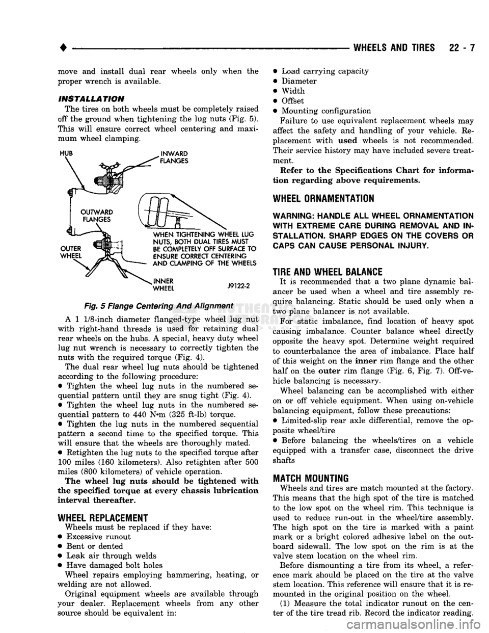
The tires on both wheels must be completely raised
off the ground when tightening the lug nuts (Fig. 5).
This will ensure correct wheel centering and maxi mum wheel clamping.
HUB
^
INWARD
Fig.
5 Flange Centering And
Alignment
A 1
1/8-inch
diameter flanged-type wheel lug nut
with right-hand threads is used for retaining dual rear wheels on the hubs. A special, heavy duty wheel lug nut wrench is necessary to correctly tighten the nuts with the required torque (Fig. 4).
The dual rear wheel lug nuts should be tightened
according to the following procedure:
• Tighten the wheel lug nuts in the numbered se
quential pattern until they are snug tight (Fig. 4).
• Tighten the wheel lug nuts in the numbered se
quential pattern to 440 N#m (325 ft-lb) torque.
• Tighten the lug nuts in the numbered sequential
pattern a second time to the specified torque. This will ensure that the wheels are thoroughly mated. • Retighten the lug nuts to the specified torque after 100 miles (160 kilometers). Also retighten after 500
miles (800 kilometers) of vehicle operation.
The wheel lug nuts should be tightened with
the specified torque at every chassis lubrication
interval thereafter.
WHEEL REPLACEMENT
Wheels must be replaced if they have:
• Excessive runout
• Bent or dented
• Leak air through welds
• Have damaged bolt holes Wheel repairs employing hammering, heating, or
welding are not allowed. Original equipment wheels are available through
your dealer. Replacement wheels from any other source should be equivalent in: • Load carrying capacity
• Diameter
® Width
• Offset
• Mounting configuration
Failure to use equivalent replacement wheels may
affect the safety and handling of your vehicle. Re
placement with used wheels is not recommended.
Their service history may have included severe treat ment.
Refer to the Specifications Chart for informa
tion regarding above requirements.
WHEEL ORNAMENTATION
WARNING; HANDLE
ALL
WHEEL ORNAMENTATION
WITH
EXTREME CARE DURING REMOVAL
AND IN
STALLATION. SHARP EDGES
ON THE
COVERS
OR
CAPS
CAN
CAUSE PERSONAL INJURY.
TIRE AND WHEEL BALANCE
It is recommended that a two plane dynamic bal
ancer be used when a wheel and tire assembly re
quire balancing. Static should be used only when a
two plane balancer is not available. For static imbalance, find location of heavy spot
causing imbalance. Counter balance wheel directly
opposite the heavy spot. Determine weight required
to counterbalance the area of imbalance. Place half of this weight on the inner rim flange and the other
half on the outer rim flange (Fig. 6, Fig. 7). Off-ve
hicle balancing is necessary. Wheel balancing can be accomplished with either
on or off vehicle equipment. When using on-vehicle
balancing equipment, follow these precautions: • Limited-slip rear axle differential, remove the op
posite wheel/tire • Before balancing the wheels/tires on a vehicle
equipped with a transfer case, disconnect the drive shafts
MATCH
MOUNTING
Wheels and tires are match mounted at the factory.
This means that the high spot of the tire is matched
to the low spot on the wheel rim. This technique is used to reduce run-out in the wheel/tire assembly.
The high spot on the tire is marked with a paint mark or a bright colored adhesive label on the out
board sidewall. The low spot on the rim is at the
valve stem location on the wheel rim. Before dismounting a tire from its wheel, a refer
ence mark should be placed on the tire at the valve stem location. This reference will ensure that it is re
mounted in the original position on the wheel. (1) Measure the total indicator runout on the cen
ter of the tire tread rib. Record the indicator reading.