timing belt DODGE TRUCK 1993 Service Repair Manual
[x] Cancel search | Manufacturer: DODGE, Model Year: 1993, Model line: TRUCK, Model: DODGE TRUCK 1993Pages: 1502, PDF Size: 80.97 MB
Page 25 of 1502
0 - 6
LUBRICATION
AND
MAINTENANCE
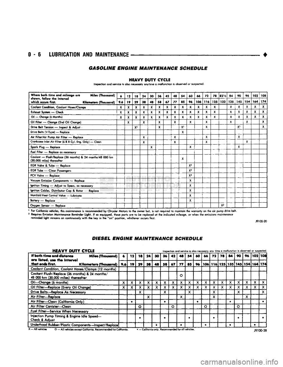
GASOLINE ENGINE MAINTENANCE SCHEDULE
HEAVY
DUTY
CYCLE
Inspection and service is also necessary anytime
a
malfunction is observed or suspected.
When both
time
and mileage
are
Miles (Thousand)
shewn,
follow
the
interval
which occurs first. Kilometers (Thousand) 6
12 18 24
30 36 42 48 54
60 66 72
78
82V2
84 90
96
102 108
When both
time
and mileage
are
Miles (Thousand)
shewn,
follow
the
interval
which occurs first. Kilometers (Thousand) 9.6 19 29
38 48 58 67 77
85 96 106 116
125 132
135
145
154 164
174
Coolant
Condition, Coolant
Hoses/Clamps
X
X X X
X X X X
X X X X
X X X
X X X
Exhaust
System
—
Check
X X X X X X X X X X X
X X X X X
X X
Oil
—
Change
(6
Months)
X X X X X X X
X X
X
X
X
X X X
X X
X
Oil
Filter
—
Change (2nd
Oil
Change)
X X X X
X X
X X
X
Drive Belt Tension
—
Inspect
&
Adjust
X' X
X1
X X' X
Drive Belts (V-Type)
—
Replace
X
Air
Filter/Air
Pump
Air
Filter
—
Replace
X X X
X
Crankcase
Inlet
Air
Filter
(6 &
8
Cyl.
Eng.
Only)
—
Clean
X X
X X
Spark
Plug
—
Replace
X X X
Fuel
Filter
—
Replace as necessary
Coolant
—
Flush/Replace
(36
months)
& 24
months/48
000 km
(30,000
miles)
thereafter
X
EGR
Valve
&
Tube
—
Replace X2
EGR
Tube
—
Clean Passengers
X2
PCV
Valve
—
Replace X2
Vacuum
Emission
Components
—
Replace
X
Ignition Timing
—
Adjust
to
Specs,
as necessary X
Ignition Cables, Distributor Cap
&
Rotor
—
Replace
X
Manifold Heat Control Valve
—
Lubricate
X
Battery
—
Replace X
Oxygen
Sensor
—
Replace
X2
1 For California vehicles, this maintenance is recommended
by
Chrysler Motors
to the
owner but, is not
required
to
maintain the
warranty
on the
air
pump drive
belt.
2 Requires
Emission
Maintenance Reminder Light.
If
so equipped, these parts
are to be
replaced
at the
indicated mileage,
or
when the
emissions
maintenance reminded light remains on continuously
with
the key in the
"on" position, whichever occurs first.
J9100-20
DIESEL
ENGINE
MAINTENANCE
SCHEDULE
HEAVY
DUTY
CYCLE
Inspection
and
service
is
also
necessary
any
time
a
malfunction
is
observed
or
suspected.
Iff both
time
and distance Miles (Thousand)
are listed, use the
interval
that
ends
first. Kilometers (Thousand) 6
12
18 24
30 36 42
4S
54
60 66
72 78
84 90 96
102 108
Iff both
time
and distance Miles (Thousand)
are listed, use the
interval
that
ends
first. Kilometers (Thousand) 9,6 19
29
38 48 58 67
77
85 96 106
116 125 135 145 154
164 174
Coolant
Condition, Coolant
Hoses/Clamps
(12 months)
Coolant
Flush/Replace (36 months) & 24 months/
48 000 km
(30,000
miles)
thereafter
O
Oil—Change
(6 months)
X X X
X X X
X X X X X
X X X X X X
X
Oil Filter—Replace (Every Oil Change)
X X X
X X X
X X
X X X
X
X X X X
X X
Drive Belts—Replace
As
Necessary
X X
X X X X
Air Filter—Replace
X X
X X
Air Filter—Clean (California Only) e
®
• •
Air
Filter
Canister—Clean
o o o
o
Fuel Filter—Service When Necessary
Injection
Pump
Timing & Engine Idle Speed—
Check
& Adjust
©
• 9 • • •
Underhood Rubber/Plastic Components—Inspect/Replace • • • • •
X
— All vehicles
O
— All
vehicles
except
California.
Recommended
for
California.
•
— California only.
Recommended
for all vehicles.
Page 33 of 1502
0 - 14
LUBRICATION
AND
MAINTENANCE
•
ENGINE
MAINTENANCE
INDEX
page
Air
Injection
Systems/Air Pump
. 17
Air-Conditioner
Compressor
21
Battery
19
Cooling System
15
Crankcase
Ventilation
System
17
Diesel Engine
Air Filter
Canister
17
Drive Belts
20
Engine
Air
Cleaner
Filter
Element
16
Engine Break-In
14
Engine
Oil 14
Engine
Oil
Change
and Filter
Replacement
15
Exhaust Gas
Recirculation
(EGR) System
...... 19
page
Exhaust
Manifold
Heat
Control
Valve
. 17
Exhaust System
, 21
Fuel System
18
Hoses
and
Fittings
16
Ignition
Cables,
Distributor
Cap and
Rotor
...... 19
Ignition
Timing
. 19
Oxygen
(02)
Sensor
19
Rubber/Plastic Components
20
Spark Plugs
. 19
Throttle
Control
Linkage
18
Vacuum Operated, Emission
Control
Components
19
ENGINE BREAK-IN
After first starting a new engine, allow it to idle
for 15 seconds before shifting into a drive gear. Also:
• Drive the vehicle at varying speeds less than 88
km/h (55 mph) for the first 480 km (300 miles).
• Avoid fast acceleration and sudden stops.
• Do not drive at full-throttle for extended periods of
time
• Do not drive at constant speeds
• Do not idle the engine excessively A special break-in engine oil is not required. The
original engine oil installed is a high quality lubri
cant. New engines tend to consume more fuel and oil un
til after the break-in period has ended.
ENGINE
OIL SPECIFICATIONS
API SERWICE
GRADE
Use an engine oil that conforms to API Service
Grade S5 SG/CD or SG/CE. MOPAR®provides engine
oils that conform to all of these service grades.
SULFATED ASH—DIESEL ENGINES
Oils that contain an excessive amount of sulfated
ash can cause deposits to develop on Diesel engine
valves. These deposits can result in valve wear.
SAE
WISC0SITY
An SAE viscosity grade is used to specify the vis
cosity of engine oil. SAE 30 specifies a single viscos
ity engine oil.
Engine oils also have multiple viscosities. 10W-30
<
5W-30
1
1 1
F
-20 0 10 20 32 60 80 100
C
-29 -18 -12 -7 0 16 27 38
ANTICIPATED
TEMPERATURE RANGE BEFORE
NEXT
OIL
CHANGE
J9000-39
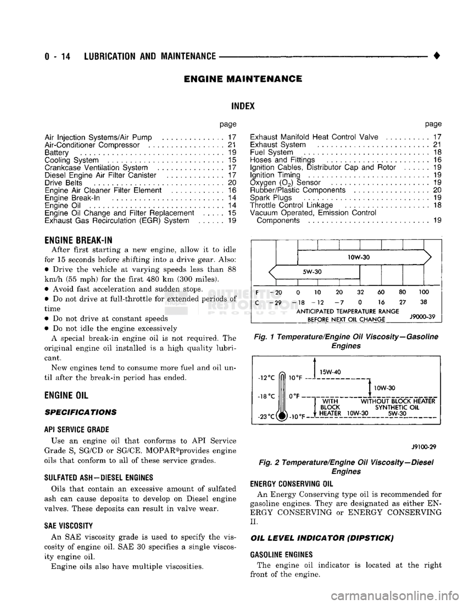
Fig.
1 Temperature/Engine Oil Viscosity—Gasoline
Engines
-12°C
-18°C 10°F
0°F- 15W-40
-23°c(^-10eF
I
10W-30
WITH
WITHOUT
BLOCK HEATER
BLOCK
SYNTHETIC
OIL
HEATER
10W-30 5W-30
J9100-29
Fig.
2 Temperature/Engine Oil Viscosity—Diesel
Engines
ENERGY
G0NSERWING
OIL
An Energy Conserving type oil is recommended for
gasoline engines. They are designated as either EN
ERGY CONSERVING or ENERGY CONSERVING
II.
OIL
LEVEL
INDICATOR (DIPSTICK)
GASOLINE ENGINES
The engine oil indicator is located at the right
front of the engine.
Page 275 of 1502
DIAGNOSIS
PRELIMINARY
CHECKS
ENGINE COOLING SYSTEM OVERHEATING Establish what driving conditions caused the com
plaint. Abnormal loads on the cooling system such as
the following may be the cause:
1.
PROLONGED IDLE, VERY HIGH AMBI
ENT TEMPERATURE, SLIGHT TAIL WIND AT
IDLE, SLOW TRAFFIC, TRAFFIC JAMS, HIGH SPEED OR STEEP GRADES.
Driving techniques that avoid overheating are:
• Idle with A/C off when temperature gauge is at
end of normal range. * Increasing engine speed for more air flow is recom
mended.
2.
TRAILER TOWING: Consult Trailer Towing section of owners manual.
Do not exceed limits.
3.
AIR CONDITIONING; ADD-ON OR AFTER
MARKET: A maximum cooling package should have been or
dered with vehicle if add-on or after market A/C is
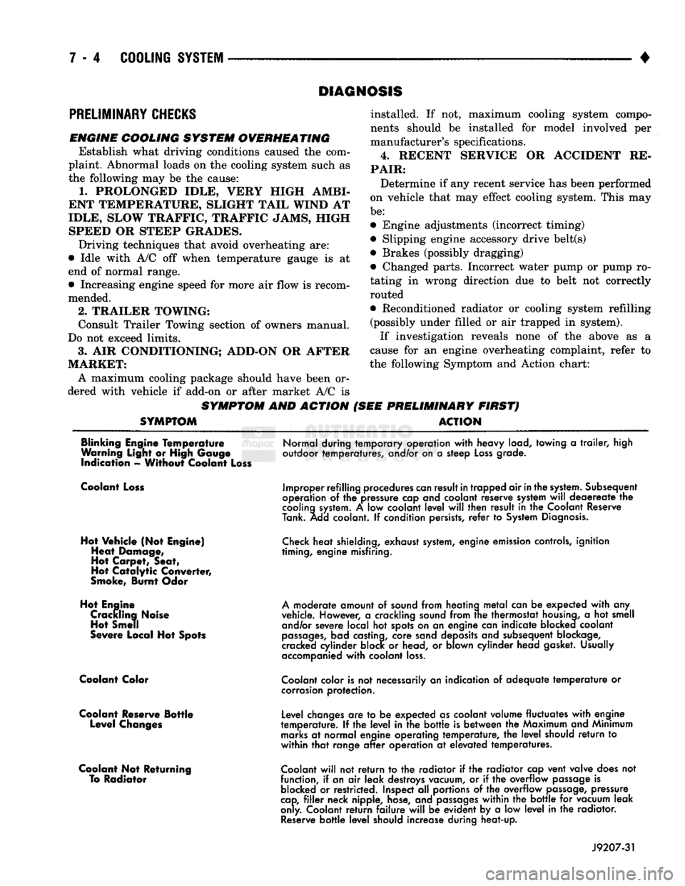
SYMPTOM AND ACTION
SYMPTOM
installed. If not, maximum cooling system compo
nents should be installed for model involved per
manufacturer's specifications.
4.
RECENT SERVICE OR ACCIDENT RE
PAIR:
Determine if any recent service has been performed
on vehicle that may effect cooling system. This may
be:
• Engine adjustments (incorrect timing)
• Slipping engine accessory drive belt(s) • Brakes (possibly dragging)
• Changed parts. Incorrect water pump or pump ro
tating in wrong direction due to belt not correctly
routed
• Reconditioned radiator or cooling system refilling (possibly under filled or air trapped in system).
If investigation reveals none of the above as a
cause for an engine overheating complaint, refer to
the following Symptom and Action chart:
PRELIMINARY FIRST) ACTION
Blinking Engine Temperature
Warning Light or High Gauge indication - Without Coolant Loss
Normal during temporary operation
with
heavy load, towing
a
trailer,
high
outdoor temperatures, and/or on
a
steep
Loss
grade.
Coolant Loss
Hot Vehicle (Not Engine) Heat Damage,
Hot Carpet, Seat,
Hot
Catalytic
Converter,
Smoke, Burnt Odor
Hot Engine Crackling Noise Hot Smell
Severe Local Hot Spots
Coolant Color
Coolant Reserve Bottle Level Changes
Coolant Not Returning To Radiator
Improper refilling procedures
can
result
in
trapped air
in
the
system.
Subsequent
operation
of the
pressure cap and coolant reserve system
will
deaereate
the
cooling
system.
A low
coolant
level
will
then result
in the
Coolant Reserve
Tank. Add coolant.
If
condition persists,
refer
to
System
Diagnosis.
Check
heat shielding, exhaust
system,
engine emission controls, ignition
timing, engine misfiring.
A
moderate amount
of
sound from heating
metal
can
be
expected
with
any
vehicle. However,
a
crackling sound from
trie
thermostat
housing,
a hot
smell and/or severe local
hot
spots on
an
engine can indicate blocked coolant
passages,
bad castina, core sand deposits and subsequent blockage,
cracked cylinder block
or
head,
or
blown cylinder head gasket. Usually
accompanied
with
coolant
loss.
Coolant
color is
not
necessarily
an
indication
of
adequate
temperature
or
corrosion
protection.
Level changes
are to be
expected as coolant volume fluctuates
with
engine
temperature.
If the
level
in the
bottle
is
between
the
Maximum and Minimum
marks
at
normal engine operating temperature,
the
level
should
return
to
within
that
range
after
operation
at
elevated temperatures.
Coolant
will
not
return
to the
radiator
if the
radiator cap vent valve does
not
function,
if
an
air
leak destroys vacuum,
or if the
overflow
passage
is
blocked
or
restricted. Inspect
all
portions
of the
overflow
passage,
pressure
cap,
filler
neck nipple, hose, and
passages
within
the
bottle
for
vacuum leak
only. Coolant
return
failure
will
be
evident
by a low
level
in the
radiator.
Reserve
bottle
level
should increase during heat-up.
J9207-31
Page 286 of 1502
•
COOLING SYSTEM
7 - 15
SERVICE
PROCEDURES
INDEX
page
Coolant
26
Coolant Reserve/Overflow System
30
Cooling System Cleaning/Reverse Flushing
28
Cooling System Fan—Diesel Engine
. 37
Cooling System
Fan—Gas
Engines
36
Cooling System
Hoses
34
Draining Cooling System
27
Pressure
Testing
Radiator
Caps
............. 32
Radiator Pressure
Cap 31
Radiators
32
Refilling
the
Cooling System
28
WATER PUMPS—EXCEPT DIESEL
A centrifugal water pump circulates coolant
through the water jackets, passages, intake manifold,
radiator core, cooling system hoses and heater core.
The pump is driven from the engine crankshaft by a drive belt. The water pump impeller is pressed onto the rear
of a shaft that rotates in a bearing pressed into the
water pump body. The body has a small hole for ven
tilation. The water pump seals are lubricated by an
tifreeze in the coolant mixture. Additional lubrication is not necessary. A quick test to determine if pump is working is to
check if heater warms properly. A defective water
pump will not be able to circulate heated coolant
through the long heater hose to the heater core. The water pump on all models can be removed
without discharging the air conditioning system (if equipped).
REMOVAL The water pump on all gas powered engines is
bolted directly to the engine timing chain case/cover.
A gasket is used as a seal between the water pump
and timing chain case/cover.
If water pump is replaced because of bearing/shaft
damage or leaking shaft seal, the mechanical cooling
fan assembly should also be inspected. Inspect for fa tigue cracks, loose blades or loose rivets that could
have resulted from excessive vibration. Replace fan if any of these conditions are found. Also check condi
tion of the thermal viscous fan drive. Refer to Vis
cous Fan Drive in this group. (1) Disconnect negative battery cable from battery.
(2) Drain cooling system. Refer to Draining Cool
ing System in this group. Do not waste reusable coolant. If solution is clean,
drain coolant into a clean container for reuse.
(3)
Disconnect throttle cable from clip at top of fan
shroud.
page
Testing
Cooling System
for
Leaks
. 29
Thermostat
22
Transmission
Oil
Cooler—Diesel
35
Transmission
Oil
Cooler—Except Diesel
35
Transmission Oil-To-Air Cooler
36
Viscous
Fan
Drive
38
Water
Pump
Bypass
Hose—All
Gas
Powered
Engines
.............................. 19
Water
Pumps—5.9L Diesel
18
Water
Pumps—Except Diesel
15
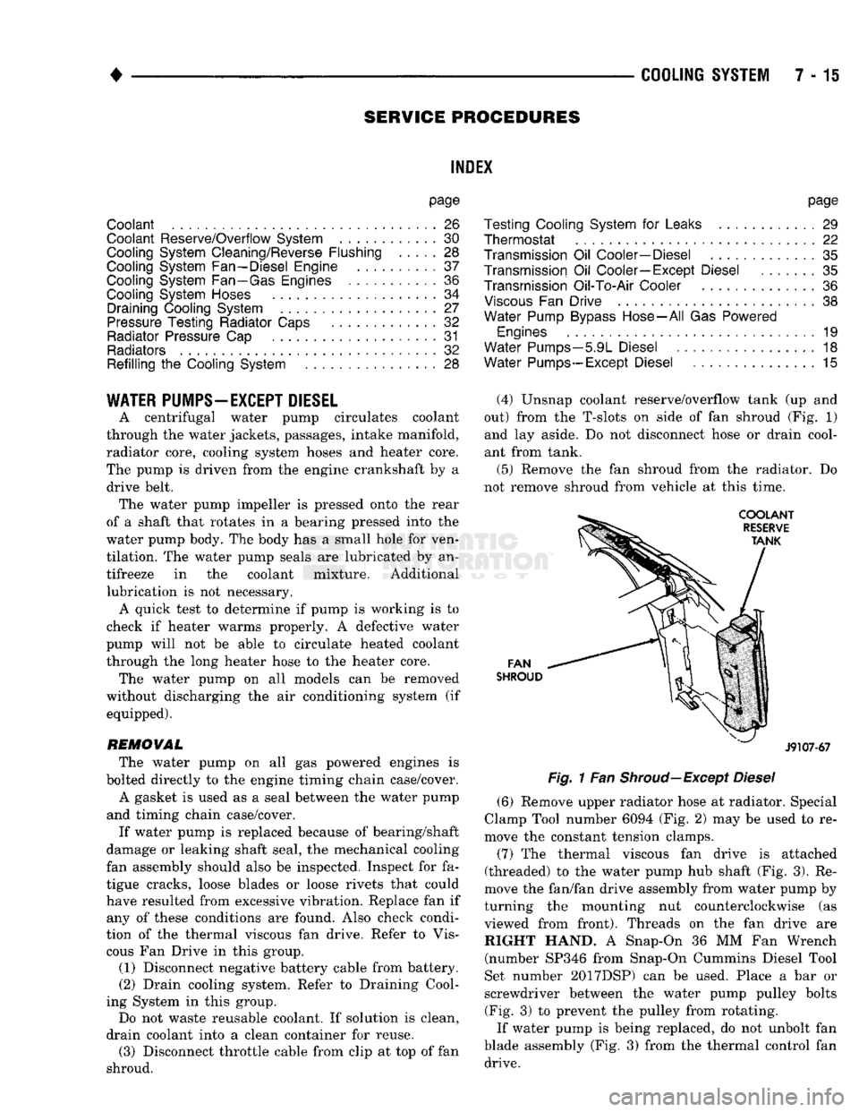
(4) Unsnap coolant reserve/overflow tank (up and
out) from the T-slots on side of fan shroud (Fig. 1) and lay aside. Do not disconnect hose or drain cool
ant from tank.
(5) Remove the fan shroud from the radiator. Do
not remove shroud from vehicle at this time.
FAN
SHROUD
J9107-67
Fig.
1 Fan
Shroud—Except
Diesel
(6) Remove upper radiator hose at radiator. Special
Clamp Tool number 6094 (Fig. 2) may be used to re
move the constant tension clamps.
(7) The thermal viscous fan drive is attached
(threaded) to the water pump hub shaft (Fig. 3). Re
move the fan/fan drive assembly from water pump by
turning the mounting nut counterclockwise (as viewed from front). Threads on the fan drive are RIGHT HAND. A Snap-On 36 MM Fan Wrench (number SP346 from Snap-On Cummins Diesel Tool
Set number 2017DSP) can be used. Place a bar or
screwdriver between the water pump pulley bolts (Fig. 3) to prevent the pulley from rotating.
If water pump is being replaced, do not unbolt fan
blade assembly (Fig. 3) from the thermal control fan drive.
Page 354 of 1502
•
IGNITION
SYSTEMS
8D - 3 For removal and installation of this sensor, refer to
the Component Removal/Installation section of this
group.
CRANKSHAFT
POSITION
SENSOR
NOTCHES- FLYWHEEL CRANKSHAFT
POSITION-
SENSOR
NOTCHES* .FLYWHEEL
J9314-88
—^^j^jV^
J9314-89
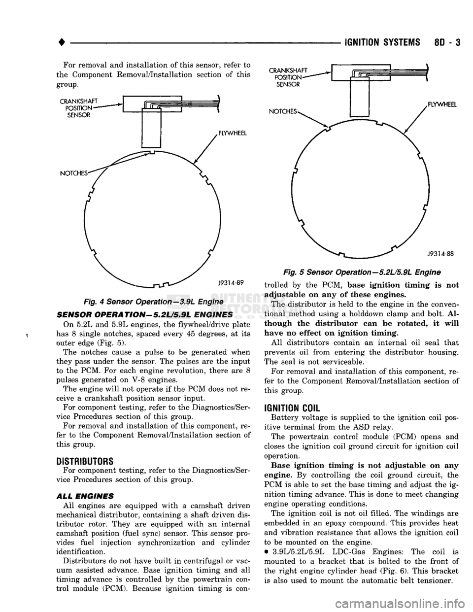
Fig.
4
Sensor
Operation—3.9L
Engine
SENSOR
OPERATION'-5.2U5.9L
ENGINES On 5.2L and 5.9L engines, the flywheel/drive plate
has 8 single notches, spaced every 45 degrees, at its outer edge (Fig. 5).
The notches cause a pulse to be generated when
they pass under the sensor. The pulses are the input to the PCM. For each engine revolution, there are 8
pulses generated on V-8 engines.
The engine will not operate if the PCM does not re
ceive a crankshaft position sensor input. For component testing, refer to the Diagnostics/Ser
vice Procedures section of this group.
For removal and installation of this component, re
fer to the Component Removal/Installation section of
this group.
DISTRIBUTORS
For component testing, refer to the Diagnostics/Ser
vice Procedures section of this group.
ALL
ENGINES All engines are equipped with a camshaft driven
mechanical distributor, containing a shaft driven dis
tributor rotor. They are equipped with an internal camshaft position (fuel sync) sensor. This sensor pro
vides fuel injection synchronization and cylinder identification.
Distributors do not have built in centrifugal or vac
uum assisted advance. Base ignition timing and all
timing advance is controlled by the powertrain con
trol module (PCM). Because ignition timing is con-
Fig.
5
Sensor
Opera tion—5.2L/5.9L
Engine
trolled by the PCM, base ignition timing is not adjustable on any of these engines.
The distributor is held to the engine in the conven
tional method using a holddown clamp and bolt. Al
though the distributor can be rotated, it will
have no effect on ignition timing.
All distributors contain an internal oil seal that
prevents oil from entering the distributor housing.
The seal is not serviceable.
For removal and installation of this component, re
fer to the Component Removal/Installation section of
this group.
IGNITION
COIL
Battery voltage is supplied to the ignition coil pos
itive terminal from the ASD relay. The powertrain control module (PCM) opens and
closes the ignition coil ground circuit for ignition coil operation. Base ignition timing is not adjustable on any
engine. By controlling the coil ground circuit, the
PCM is able to set the base timing and adjust the ig nition timing advance. This is done to meet changing engine operating conditions. The ignition coil is not oil filled. The windings are
embedded in an epoxy compound. This provides heat and vibration resistance that allows the ignition coil
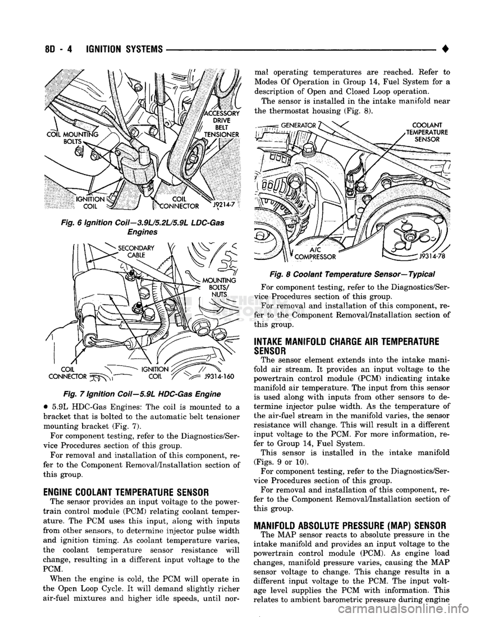
to be mounted on the engine. • 3.9L/5.2L/5.9L LDC-Gas Engines: The coil is
mounted to a bracket that is bolted to the front of the right engine cylinder head (Fig. 6). This bracket is also used to mount the automatic belt tensioner.
Page 355 of 1502
8D
- 4
IGNITION
SYSTEMS
•
Fig. 6 ignition Coil—3.9L/5.2L/5.9L
LDC-Gas
Engines Fig. 7 Ignition Coil—5.9L
HDC-Gas
Engine
• 5.9L HDC-Gas Engines: The coil is mounted to a
bracket that is bolted to the automatic belt tensioner mounting bracket (Fig. 7).
For component testing, refer to the Diagnostics/Ser
vice Procedures section of this group.
For removal and installation of this component, re
fer to the Component Removal/Installation section of
this group.
ENGINE COOLANT TEMPERATURE
SENSOR
The sensor provides an input voltage to the power-
train control module (PCM) relating coolant temper ature. The PCM uses this input, along with inputs
from other sensors, to determine injector pulse width and ignition timing. As coolant temperature varies,
the coolant temperature sensor resistance will
change, resulting in a different input voltage to the
PCM. When the engine is cold, the PCM will operate in
the Open Loop Cycle. It will demand slightly richer air-fuel mixtures and higher idle speeds, until nor mal operating temperatures are reached. Refer to
Modes Of Operation in Group 14, Fuel System for a
description of Open and Closed Loop operation.
The sensor is installed in the intake manifold near
the thermostat housing (Fig. 8).
Fig. 8 Coolant Temperature Sensor—Typical
For component testing, refer to the Diagnostics/Ser
vice Procedures section of this group. For removal and installation of this component, re
fer to the Component Removal/Installation section of
this group.
INTAKE MANIFOLD CHARGE
AIR
TEMPERATURE
SENSOR
The sensor element extends into the intake mani
fold air stream. It provides an input voltage to the
powertrain control module (PCM) indicating intake
manifold air temperature. The input from this sensor is used along with inputs from other sensors to de
termine injector pulse width. As the temperature of
the air-fuel stream in the manifold varies, the sensor
resistance will change. This will result in a different input voltage to the PCM. For more information, re
fer to Group 14, Fuel System. This sensor is installed in the intake manifold
(Figs.
9 or 10). For component testing, refer to the Diagnostics/Ser
vice Procedures section of this group. For removal and installation of this component, re
fer to the Component Removal/Installation section of
this group.
MANIFOLD ABSOLUTE
PRESSURE
(MAP)
SENSOR
The MAP sensor reacts to absolute pressure in the
intake manifold and provides an input voltage to the
powertrain control module (PCM). As engine load changes, manifold pressure varies, causing the MAP
sensor voltage to change. This change results in a
different input voltage to the PCM. The input volt age level supplies the PCM with information. This
relates to ambient barometric pressure during engine
Page 372 of 1502
IGNITION
SYSTEMS
80 - 21
DISTRIBUTOR
J9314-81
Fig.
7 Rotor Alignment Mark Fig. 8 Distributor Holddown Clamp
INSTALLATION
If engine has been cranked while distributor is re
moved, establish the relationship between distributor shaft and number one piston position as follows:
Rotate crankshaft in a clockwise direction, as
viewed from front, until number one cylinder piston is at top of compression stroke (compression should
be felt on finger with number one spark plug re moved). Then continue to slowly rotate engine clock
wise until indicating mark (Fig. 6) is aligned to 0
degree (TDC) mark on timing chain cover.
(1) Clean top of cylinder block for a good seal be
tween distributor base and block.
(2) Lightly oil the rubber O-ring seal on the dis
tributor housing.
(3) Install rotor to distributor shaft.
(4) Position distributor into engine to its original
position. Engage tongue of distributor shaft with slot in distributor oil pump drive gear. Position rotor to
the number one spark plug cable position.
(5) Install distributor holddown clamp and clamp
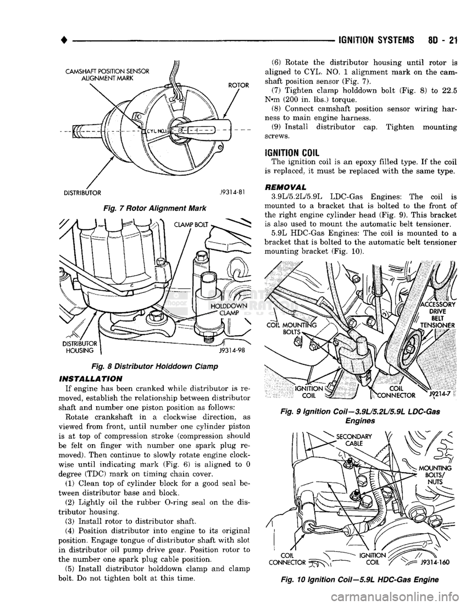
bolt. Do not tighten bolt at this time. (6) Rotate the distributor housing until rotor is
aligned to CYL. NO. 1 alignment mark on the cam
shaft position sensor (Fig. 7).
(7) Tighten clamp holddown bolt (Fig. 8) to 22.5
N*m (200 in. lbs.) torque. (8) Connect camshaft position sensor wiring har
ness to main engine harness. (9) Install distributor cap. Tighten mounting
screws.
IGNITION
COIL
The ignition coil is an epoxy filled type. If the coil
is replaced, it must be replaced with the same type.
REMOVAL
3.9L/5.2L/5.9L LDC-Gas Engines: The coil is
mounted to a bracket that is bolted to the front of
the right engine cylinder head (Fig. 9). This bracket is also used to mount the automatic belt tensioner.
5.9L HDC-Gas Engines: The coil is mounted to a
bracket that is bolted to the automatic belt tensioner mounting bracket (Fig. 10).
Fig.
9 Ignition Coil-3.9U5.2U5.9L
LDC-Gas
Engines
Fig.
10 Ignition Coil—5.9L
HDC-Gas
Engine
Page 607 of 1502
9
- 2
ENGINES
rial surrounds each mounting hole. Excess material
can easily be wiped off. Components should be
torqued in place within 15 minutes. The use of a lo cating dowel is recommended during assembly to pre
vent smearing the material off location.
ENGINE PERFORMANCE
To provide best vehicle performance and lowest ve
hicle emissions, it is most important that the tune-up
be done accurately. Use the specifications listed on
the Vehicle Emission Control Information label found on the engine compartment hood.
(1) Test cranking amperage draw (refer to Group
8B,
Battery/Starter/Generator Service for the proper
procedures).
(2) Tighten the intake manifold bolts (refer to
Group 11, Exhaust System and Intake Manifold for
the proper specifications). (3) Perform cylinder compression test:
(a) Check engine oil level and add oil, if neces
sary.
(b) Drive the vehicle until engine reaches normal
operating temperature. (c) Select a route free from traffic and other
forms of congestion, observe all traffic laws and
briskly accelerate through the gears several times. The higher engine speed may help clean out valve seat deposits which can prevent accurate compres
sion readings.
CAUTION:
DO NOT
overspeed
the
engine.
(d) Remove all spark plugs from engine. As
spark plugs are being removed, check electrodes for
abnormal firing indicators - fouled, hot, oily, etc.
Record cylinder number of spark plug for future
reference.
(e) Disconnect coil wire from distributor and se
cure to good ground to prevent a spark from start
ing a fire.
(f) Be sure throttle blades are fully open during
the compression check. (g) Insert compression gage adaptor into the
No.l spark plug hole. Crank engine until maxi
mum pressure is reached on gauge. Record this
pressure as No.l cylinder pressure.
(h) Repeat Step 3g for all remaining cylinders.
(i) Compression should not be less than 689 kPa
(100 psi) and not vary more than 172 kPa (25 psi)
from cylinder to cylinder.
(j) If cylinder(s) have abnormally low compres
sion pressures, repeat steps 3a through 3h. (k) If the same cylinder(s) repeat an abnormally
low reading, it could indicate the existence of a
problem in the cylinder.
The recommended compression pressures are
to be used only as a guide to diagnosing engine
problems. An engine should NOT be disassem bled to determine the cause of low compression
unless some malfunction is present. (4) Clean or replace spark plugs as necessary. Ad
just gap (refer to Group 8D, Ignition System for gap adjustment and torque).
(5) Test resistance of spark plug cables (refer to
Group 8D, Ignition System.
(6) Inspect the primary wire. Test coil output volt
age,
primary and secondary resistance. Replace parts as necessary (refer to Group 8D, Ignition System and
make necessary adjustment).
(7) Set ignition timing to specifications (refer to
Specification Label on engine compartment hood).
(8) Perform a combustion analysis.
(9) Test fuel pump for pressure and vacuum (refer
to Group 14, Fuel System for the proper specifica
tions).
(10) Inspect air filter element (refer to Group 0,
Lubrication and Maintenance for the proper proce
dure).
(11) Inspect crankcase ventilation system (refer to
Group 0, Lubrication and Maintenance for the proper
procedure).
(12) For emission controls refer to Group 25, Emis
sion Controls System for service procedures.
(13) Inspect and adjust accessory belt drives (refer
to Group 7, Cooling System for the proper adjust
ments).
(14) Road test vehicle as a final test.
H0NIN6
CYLINDER
BORES
Before honing, stuff plenty of clean shop towels un
der the bores and over the crankshaft to keep abra sive materials from entering the crankshaft area.
(1) Used carefully, the Cylinder Bore Sizing Hone
C-823 equipped with 220 grit stones, is the best tool
for this job. In addition to deglazing, it will reduce
taper and out-of-round as well as removing light scuffing, scoring or scratches. Usually a few strokes
will clean up a bore and maintain the required lim
its.
CAUTION:
DO NOT use rigid type
hones
to remove
cylinder
wall
glaze.
(2) Deglazing of the cylinder walls may be done if
the cylinder bore is straight and round. Use a cylin
der surfacing hone, Honing Tool C-3501, equipped
with 280 grit stones (C-3501-3810). 20-60 strokes, de
pending on the bore condition, will be sufficient to
provide a satisfactory surface. Using honing oil C-3501-3880 or a light honing oil available from ma
jor oil distributors.
CAUTION:
DO NOT use engine or
transmission
oil, mineral
spirits
or
kerosene.
Page 617 of 1502
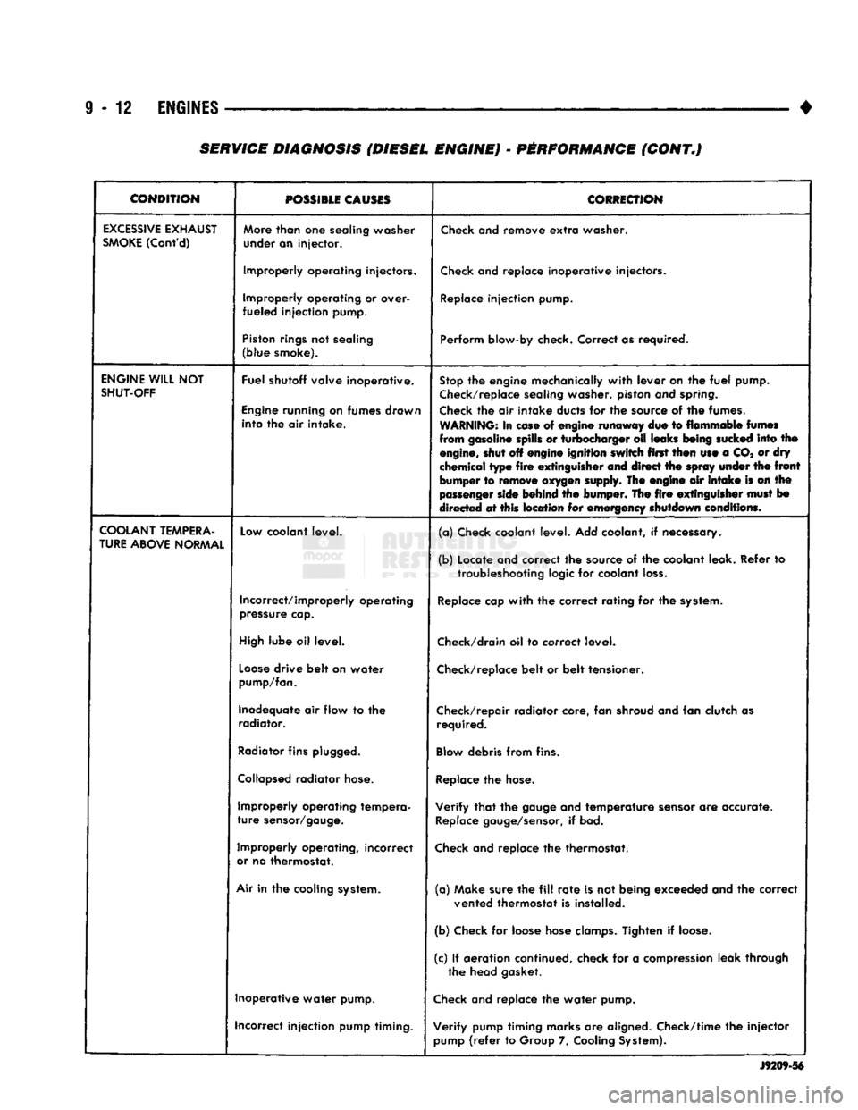
9
- 12
ENGINES
•
CONDITION
POSSIBLE
CAUSES
CORRECTION
EXCESSIVE
EXHAUST
SMOKE
(Cont'd)
More
than
one
sealing washer
under an injector.
Check
and remove
extra
washer.
Improperly operating injectors.
Check
and replace inoperative injectors.
Improperly operating or over-
fueled injection pump.
Replace
injection pump.
Piston
rings
not sealing
(blue smoke). Perform blow-by check. Correct as required.
ENGINE
WILL
NOT
SHUT-OFF
Fuel shutoff valve inoperative.
Engine
running on fumes drawn into the air intake.
Stop
the engine mechanically
with
lever on the
fuel
pump.
Check/replace
sealing washer, piston and
spring.
Check
the air intake ducts for the source of the fumes.
WARNING:
In
ease
of engine runaway due to flammable
fumes
from gasoline spills or turbocharger oil leaks
being
sucked
into the
engine,
shut off engine ignition switch first then use a CO* or dry
chemical type
fire
extinguisher
and direct the
spray
under
the
front
bumper to
remove
oxygen
supply. The engine air
intake
is on the
passenger
side
behind the bumper. The
fire
extinguisher
must
bo
directed at this location for emergency shutdown conditions.
COOLANT
TEMPERA
TURE
ABOVE
NORMAL
Low
coolant level.
(a) Check coolant level. Add coolant, if necessary.
(b) Locate and correct the source of the coolant leak. Refer to
troubleshooting
logic for coolant
loss.
Incorrect/improperly operating
pressure
cap.
Replace
cap
with
the correct rating for the
system.
High
lube oil level.
Check/drain
oil to correct level.
Loose
drive belt on water
pump/fan.
Check/replace
belt or belt tensioner.
Inadequate air flow to the radiator. Check/repair radiator core, fan shroud and fan clutch as
required.
Radiator
fins
plugged.
Blow
debris from fins.
Collapsed
radiator
hose.
Replace
the
hose.
Improperly operating tempera
ture
sensor/gauge.
Verify
that
the
gauge
and temperature
sensor
are accurate.
Replace
gauge/sensor,
if bad.
Improperly operating, incorrect
or
no thermostat.
Check
and replace the thermostat.
Air
in the cooling
system.
(a) Make sure the
fill
rate
is not being exceeded and the correct
vented thermostat is installed.
(b) Check for loose hose
clamps.
Tighten if
loose.
(c) If aeration continued, check for a
compression
leak through the head gasket.
Inoperative water pump.
Check
and replace the water pump.
incorrect injection pump timing. Verify pump timing marks are aligned. Check/time the injector
pump
(refer
to Group 7,
Cooling
System).
J9209-56
SERVICE DIAGNOSIS (DIESEL ENGINE) - PERFORMANCE (CONT.)
Page 634 of 1502
•
3.9L
ENGINE
I - 21
VIBRATION
DAMPER
REMOVAL
(1) Disconnect the negative cable from the battery,
(2) Remove fan shroud retainer bolts and set
shroud back over engine.
(3) Remove the cooling system fan.
(4) Remove the serpentine belt (refer to Group 7,
Cooling System).
(5) Remove the vibration damper pulley.
(6) Remove vibration damper bolt and washer from
end of crankshaft.
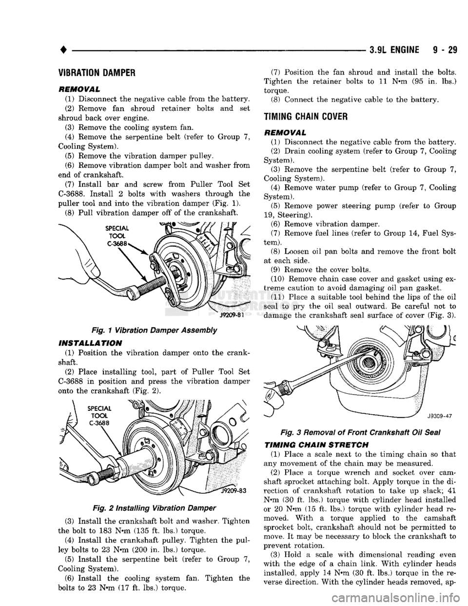
(7) Install bar and screw from Puller Tool Set
C-3688.
Install 2 bolts with washers through the
puller tool and into the vibration damper (Fig. 1).
(8) Pull vibration damper off of the crankshaft.
J9209-81
Fig. 1 Vibration
Damper
Assembly INSTALLATION
(1) Position the vibration damper onto the crank
shaft.
(2) Place installing tool, part of Puller Tool Set
C-3688 in position and press the vibration damper
onto the crankshaft (Fig. 2).
Fig. 2 Installing Vibration Damper
(3) Install the crankshaft bolt and washer. Tighten
the bolt to 183 N*m (135 ft. lbs.) torque.
(4) Install the crankshaft pulley. Tighten the pul
ley bolts to 23 N*m (200 in. lbs.) torque.
(5) Install the serpentine belt (refer to Group 7,
Cooling System).
(6) Install the cooling system fan. Tighten the
bolts to 23 N*m (17 ft. lbs.) torque. (7) Position the fan shroud and install the bolts.
Tighten the retainer bolts to 11 N*m (95 in. lbs.)
torque.
(3)
Connect the negative cable to the battery.
TIMING CHAIN
COVER
REMOVAL (1)
Disconnect the negative cable from the battery.
(2)
Drain cooling system (refer to Group 7, Cooling
System).
(3)
Remove the serpentine belt (refer to Group 7,
Cooling System).
(4)
Remove water pump (refer to Group 7, Cooling
System).
(5)
Remove power steering pump (refer to Group
19,
Steering).
(6)
Remove vibration damper. (7) Remove fuel lines (refer to Group 14, Fuel Sys
tem).
(8) Loosen oil pan bolts and remove the front bolt
at each side.
(9)
Remove the cover bolts.
(10)
Remove chain case cover and gasket using ex
treme caution to avoid damaging oil pan gasket.
(11)
Place a suitable tool behind the lips of the oil
seal to pry the oil seal outward. Be careful not to
damage the crankshaft seal surface of cover (Fig. 3). Fig. 3 Removal of Front Crankshaft Oil Seal
TIMING CHAIN STRETCH
(1) Place a scale next to the timing chain so that
any movement of the chain may be measured.
(2)
Place a torque wrench and socket over cam
shaft sprocket attaching bolt. Apply torque in the di
rection of crankshaft rotation to take up slack; 41
N#m (30 ft. lbs.) torque with cylinder head installed or 20 N»m (15 ft. lbs.) torque with cylinder head re
moved. With a torque applied to the camshaft sprocket bolt, crankshaft should not be permitted to
move. It may be necessary to block the crankshaft to
prevent rotation.
(3)
Hold a scale with dimensional reading even
with the edge of a chain link. With cylinder heads installed, apply 14 N*m (30 ft. lbs.) torque in the re
verse direction. With the cylinder heads removed, ap-