power steering DODGE VIPER 2008 ZB II / 2.G Owners Manual
[x] Cancel search | Manufacturer: DODGE, Model Year: 2008, Model line: VIPER, Model: DODGE VIPER 2008 ZB II / 2.GPages: 303, PDF Size: 2.65 MB
Page 93 of 303
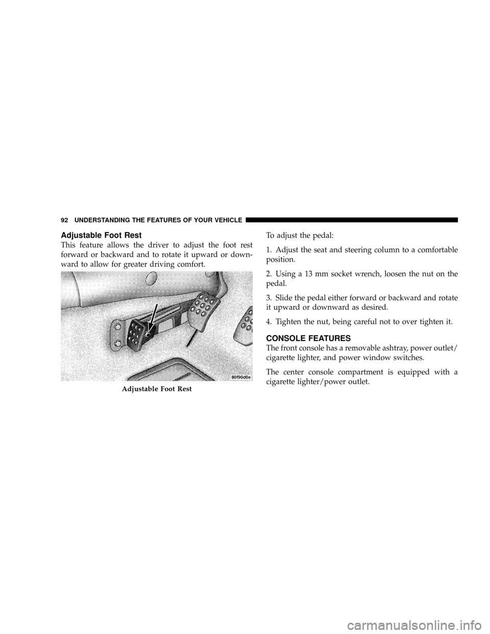
Adjustable Foot Rest
This feature allows the driver to adjust the foot rest
forward or backward and to rotate it upward or down-
ward to allow for greater driving comfort.To adjust the pedal:
1. Adjust the seat and steering column to a comfortable
position.
2. Using a 13 mm socket wrench, loosen the nut on the
pedal.
3. Slide the pedal either forward or backward and rotate
it upward or downward as desired.
4. Tighten the nut, being careful not to over tighten it.
CONSOLE FEATURES
The front console has a removable ashtray, power outlet/
cigarette lighter, and power window switches.
The center console compartment is equipped with a
cigarette lighter/power outlet.
Adjustable Foot Rest
92 UNDERSTANDING THE FEATURES OF YOUR VEHICLE
Page 108 of 303
you understand and save you concern about these ªap-
parentº malfunctions, you must understand a point or
two about the transmission and reception of radio sig-
nals.
Two Types of Signals
There are two basic types of radio signals: AM or
Amplitude Modulation, in which the transmitted sound
causes the amplitude, or height, of the radio waves to
vary; and FM or Frequency Modulation, in which the
frequency of the wave is varied to carry the sound.
Electrical Disturbances
Radio waves may pick up electrical disturbances during
transmission. They mainly affect the wave amplitude,
and thus remain a part of the AM reception. They
interfere very little with the frequency variations that
carry the FM signal.
AM Reception
AM sound is based on wave amplitude, so AM reception
can be disrupted by such things as lightning, power lines
and neon signs.
FM Reception
Because FM transmission is based on frequency varia-
tions, interference that consists of amplitude variations
can be filtered out, leaving the reception relatively clear,
which is the major feature of FM radio.
NOTE:The radio, steering wheel radio controls (if
equipped), and 6±Disc CD/DVD changer (if equipped)
will remain active for up to 10 minutes after the ignition
switch has been turned OFF. Opening a vehicle front
door will cancel this feature.
UNDERSTANDING YOUR INSTRUMENT PANEL 107
4
Page 130 of 303
STARTING AND OPERATING
CONTENTS
mStarting Procedures.....................132
NNormal Starting......................133
NIf Engine Fails To Start.................135
NAfter Starting........................136
mTransmission Shifting....................136
NRecommended Shift Speeds..............138
NSkip Shift Indicator Light................138
mDriving On Slippery Surfaces..............139
NAcceleration.........................139NTraction............................140
mDriving Through Water..................140
NFlowing/Rising Water..................141
NShallow Standing Water.................141
mParking Brake.........................142
mBrake System..........................144
NBrake Pad Break-In....................144
NAnti-Lock Brake System................145
mPower Steering........................148
5
Page 149 of 303
POWER STEERING
The standard power steering system will give you good
vehicle response and increased ease of maneuverability
in tight spaces. The system will provide mechanical
steering capability if power assist is lost.
If for some reason the power assist is interrupted, it will
still be possible to steer your vehicle. Under these condi-
tions, you will observe a substantial increase in steering
effort, especially at very low vehicle speeds and during
parking maneuvers.
NOTE:Increased noise levels at the end of the steering
wheel travel are considered normal and do not indicate
that there is a problem with the power steering system.
Upon initial start-up in cold weather, the power steering
pump may make noise for a short amount of time. This is
due to the cold, thick fluid in the steering system. This
noise should be considered normal, and it does not in any
way damage the steering system.WARNING!
Continued operation with reduced power steering
assist could pose a safety risk to yourself and others.
Service should be obtained as soon as possible.
CAUTION!
Prolonged operation of the steering system at the end
of the steering wheel travel will increase the steering
fluid temperature and it should be avoided when
possible. Damage to the power steering pump may
occur.
148 STARTING AND OPERATING
Page 184 of 303
²Turn the Mode Select knob to the Sealant/Air Mode.
²Connect the Power Plug (5) to a different power
outlet in your vehicle or another vehicle, if available.
Make sure the engine is running before turning on
the TIREFIT kit.
²The Sealant Bottle (1) may be empty due to previous
use. Call for assistance.
(D) After Injecting TIREFIT Sealant:
1. Allow the air pump to inflate the tire to the pressure
indicated on the tire pressure label on the driver-side
latch pillar. Check the pressure in the tire by looking at
the Pressure Gauge (2).
²If the tire inflates to at least 26 psi (1.8 bar) within 15
minutes, proceed to Step 2 of this procedure.
²If tire fails to inflate to 26 psi (1.8 bar) within 15
minutes, perform the procedure steps described
under ª(G) Distributing TIREFIT Sealant to Better
Enable Tire Inflation.º
²Press the Air Pump Power Button (3) to
turn off the TIREFIT kit.
2. Remove the Speed Limit sticker from the top of the
Sealant Bottle (1) and place the sticker on the steering
wheel.
3. Disconnect the TIREFIT kit from the valve stem and
place it in the vehicle.
(E) Securing TIREFIT Sealant in the Tire
Drive the vehicle for approximately 5 miles (8 km) to
ensure distribution of the TIREFIT Sealant within the tire.
WHAT TO DO IN EMERGENCIES 183
6
Page 193 of 303
NBattery Save Feature...................210
NAir Conditioner Maintenance.............212
NPower Steering Ð Fluid Check............213
NFront & Rear Suspension Ball Joints........214
NSteering Linkage......................214
NBody Lubrication.....................215
NBody Mechanism Lubrication.............215
NWindshield Wiper Blades................217
NWindshield Washers...................217
NExhaust System......................218
NCooling System.......................219
NHoses And Vacuum/Vapor Harnesses.......224NFuel System.........................224
NBrake System........................225
NTransmission........................228
NHydraulic Clutch.....................228
NRear Axle...........................230
NWheel Bearings.......................230
NAppearance Care And Protection From
Corrosion...........................230
mFuses (Power Distribution Centers)..........234
NFuses (Power Distribution Center).........234
NFuses (Mini-Power Distribution Center).....237
mVehicle Storage........................238
192 MAINTAINING YOUR VEHICLE
Page 203 of 303
quality filters should be used to assure most efficient
service. MopartEngine Oil Filters are a high quality oil
filter and are recommended.
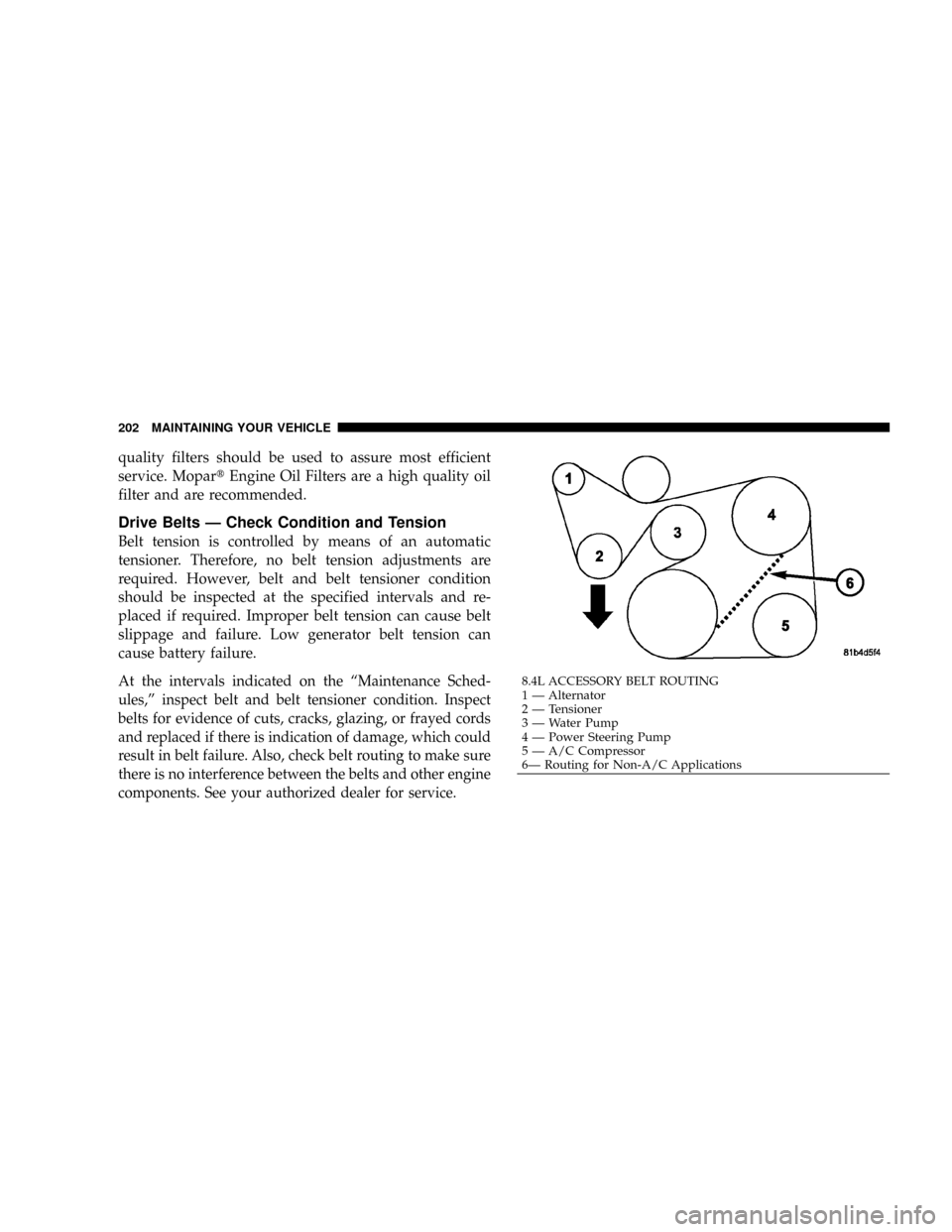
Drive Belts Ð Check Condition and Tension
Belt tension is controlled by means of an automatic
tensioner. Therefore, no belt tension adjustments are
required. However, belt and belt tensioner condition
should be inspected at the specified intervals and re-
placed if required. Improper belt tension can cause belt
slippage and failure. Low generator belt tension can
cause battery failure.
At the intervals indicated on the ªMaintenance Sched-
ules,º inspect belt and belt tensioner condition. Inspect
belts for evidence of cuts, cracks, glazing, or frayed cords
and replaced if there is indication of damage, which could
result in belt failure. Also, check belt routing to make sure
there is no interference between the belts and other engine
components. See your authorized dealer for service.8.4L ACCESSORY BELT ROUTING
1 Ð Alternator
2 Ð Tensioner
3 Ð Water Pump
4 Ð Power Steering Pump
5 Ð A/C Compressor
6Ð Routing for Non-A/C Applications 202 MAINTAINING YOUR VEHICLE
Page 214 of 303
Refrigerant Recovery and Recycling
R-134a Air Conditioning Refrigerant is a hydrofluorocar-
bon (HFC) that is endorsed by the Environmental Pro-
tection Agency and is an ozone-saving product. How-
ever, the manufacturer recommends that air conditioning
service be performed by dealers or other service facilities
using recovery and recycling equipment.
NOTE:Use only manufacturer approved A/C System
Sealers, Stop Leak Products, Seal Conditioners, Compres-
sor Oil, and Refrigerants.
Power Steering Ð Fluid Check
Check the fluid level in the power steering fluid reservoir
at the specified intervals. Refer to ªMaintenance Sched-
ulesº in this manual.
Check the fluid HOT with the engine OFF.
WARNING!
Fluid level should be checked with the engine off to
prevent injury from moving parts and on a level
surface to insure accurate fluid level reading.
If adding fluid, use only the manufacturer's recom-
mended fluid as it is specially formulated for minimum
effect on the rubber hoses in the power steering system.
Refer to ªFluids, Lubricants and Genuine Partsº in this
section for the correct fluid type.
Before removing the reservoir cap, wipe the outside of
the cap and reservoir so that no dirt can fall into the
reservoir
Add fluid to bring the level up to the requirements
described on the reservoir. Do not overfill. Wipe any
spilled fluid from all surfaces with a clean cloth.
MAINTAINING YOUR VEHICLE 213
7
Page 215 of 303
WARNING!
Overfilling the power steering fluid reservoir can
result in spilling power steering fluid on hot engine
parts and the power steering fluid catching fire.
Front & Rear Suspension Ball Joints
This vehicle has suspension ball joints that require peri-
odic inspection and lubrication.
Inspection
The ball joints should be inspected whenever other
service or maintenance is performed on the vehicle.
Damaged seals should be replaced to prevent leakage or
contamination of the grease. If there is any movement
within the ball joint, the knuckle or control arm must be
replaced, as the ball joints are not serviceable by them-
selves. See your authorized dealer for service.
Lubrication
The ball joints are lubricated at the factory with special
grease. Therefore, when lubricating the ball joints, use
only special long life chassis grease such as Multi-
Mileage Lubricant, which is intended for this purpose.
Refer to the ªMaintenance Schedulesº in this manual for
the specified lubrication intervals.
Steering Linkage
There are two tie rod end ball joints that require periodic
inspection.
Inspection
The ball joint seals on the tie rod ends should be
inspected whenever other service or maintenance is
performed on the vehicle. Damaged seals should be
replaced to prevent leakage or contamination of the
grease. If damaged, the tie rod end must be replaced, as
the seals are not serviceable by themselves. See your
authorized dealer for service.
214 MAINTAINING YOUR VEHICLE
Page 226 of 303
Brake System
In order to assure brake system performance, all brake
system components should be inspected periodically.
Recommended service intervals can be found in the
ªMaintenance Schedulesº in this manual.
WARNING!
Riding the brakes can lead to brake failure and
possibly an accident. Driving with your foot resting
or riding on the brake pedal can result in abnormally
high brake temperatures, excessive lining wear, and
possible brake damage. You wouldn't have your full
braking capacity in an emergency.
Brake and Power Steering Hoses
When servicing the vehicle for scheduled maintenance,
inspect surface of hoses and nylon tubing for evidence of
heat and mechanical damage. Hard and brittle rubber,cracking, checking, tears, cuts, abrasion, and excessive
swelling suggest deterioration of the rubber. Particular
attention should be made to examining those hose sur-
faces nearest to high heat sources, such as the exhaust
manifold.
Insure nylon tubing in these areas has not melted or
collapsed.
Inspect all hose clamps and couplings to make sure they
are secure and no leaks are present.
NOTE:
²Often, fluid such as oil, power steering fluid, and
brake fluid are used during assembly plant operations
to facilitate the assembly of hoses to couplings. There-
fore, oil wetness at the hose-coupling area is not
necessarily an indication of leakage. Actual dripping
of hot fluid when systems are under pressure (during
vehicle operation), should be noted before a hose is
replaced based on leakage.
MAINTAINING YOUR VEHICLE 225
7