clock DODGE VIPER 2010 ZB II / 2.G User Guide
[x] Cancel search | Manufacturer: DODGE, Model Year: 2010, Model line: VIPER, Model: DODGE VIPER 2010 ZB II / 2.GPages: 80, PDF Size: 8.08 MB
Page 11 of 80
MANUAL DOOR LOCK
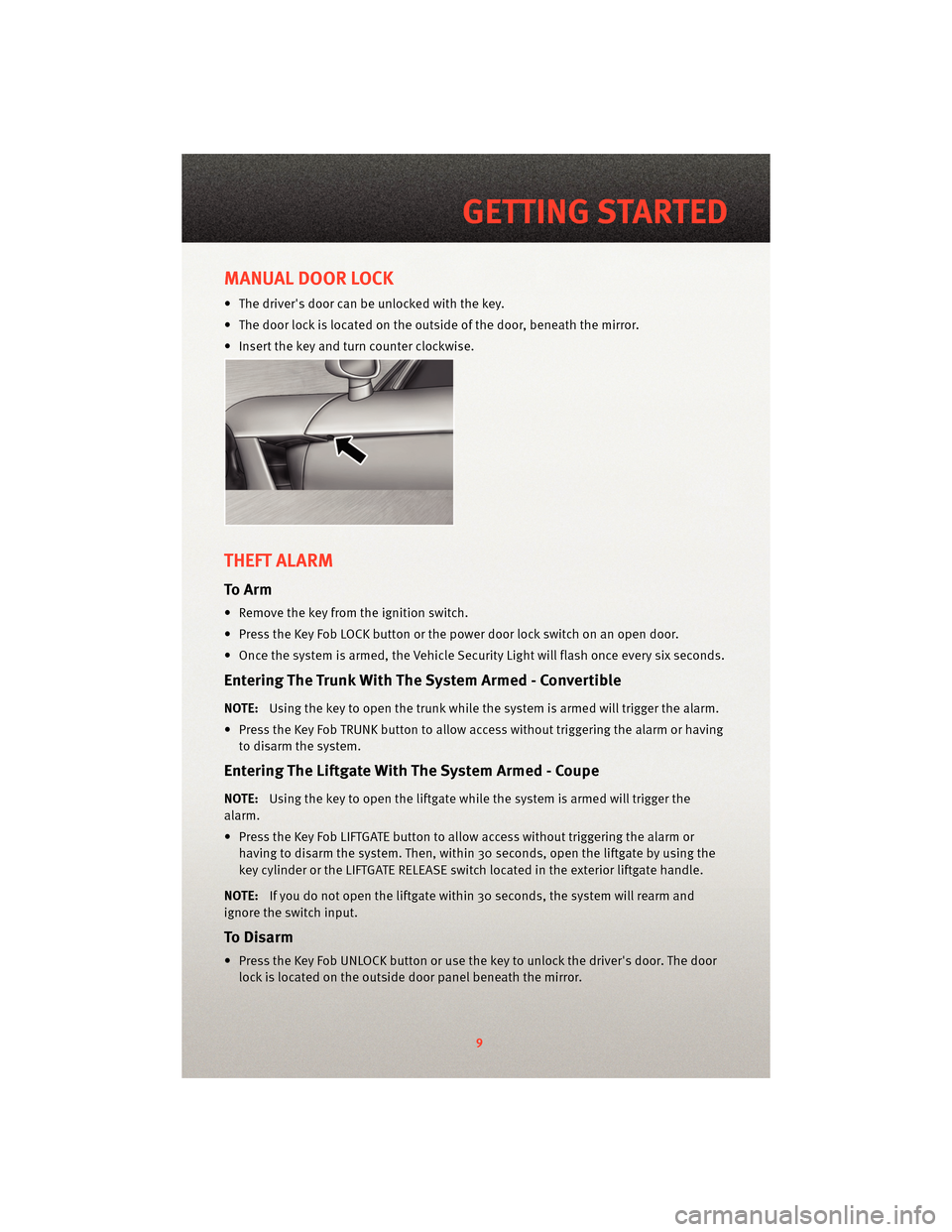
• The driver's door can be unlocked with the key.
• The door lock is located on the outside of the door, beneath the mirror.
• Insert the key and turn counter clockwise.
THEFT ALARM
To Arm
• Remove the key from the ignition switch.
• Press the Key Fob LOCK button or the power door lock switch on an open door.
• Once the system is armed, the Vehicle Security Light will flash once every six seconds.
Entering The Trunk With The System Armed - Convertible
NOTE:Using the key to open the trunk while the system is armed will trigger the alarm.
• Press the Key Fob TRUNK button to allow access without triggering the alarm or having to disarm the system.
Entering The Liftgate With The System Armed - Coupe
NOTE: Using the key to open the liftgate while the system is armed will trigger the
alarm.
• Press the Key Fob LIFTGATE button to allow access without triggering the alarm or having to disarm the system. Then, within 30 seconds, open the liftgate by using the
key cylinder or the LIFTGATE RELEASE switch located in the exterior liftgate handle.
NOTE: If you do not open the liftgate within 30 seconds, the system will rearm and
ignore the switch input.
To Disarm
• Press the Key Fob UNLOCK button or use the key to unlock the driver's door. The door lock is located on the outside door panel beneath the mirror.
9
GETTING STARTED
Page 25 of 80
Clock Setting
• Turn the ignition switch to the ON/RUN or ACC position.
• Using the point of a ballpoint pen or similar object, press either the H (HOUR) or M(MINUTE) button on the radio. The display will show the time.
• Press the “H” button to set hours or the “M” button to set minutes. The time setting
will increase each time you press a button.
Station Presets
• Press the SET button once and SET 1 will show in the display. Then select the button (1–5).
• A second station may be added to each pushbutton. Press the SET button twice and SET 2 will show in the display, then select button (1–5).
23
ELECTRONICS
Page 26 of 80
NON-TOUCH-SCREEN RADIO
Navigation Radio – RB1
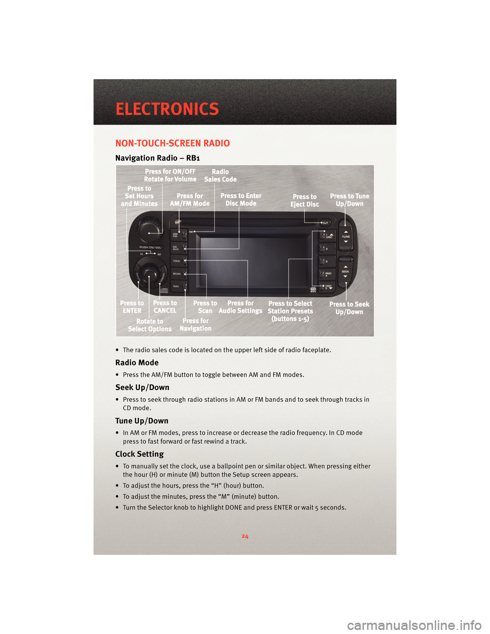
• The radio sales code is located on the upper left side of radio faceplate.
Radio Mode
• Press the AM/FM button to toggle between AM and FM modes.
Seek Up/Down
• Press to seek through radio stations in AM or FM bands and to seek through tracks inCD mode.
Tune Up/Down
• In AM or FM modes, press to increase or decrease the radio frequency. In CD modepress to fast forward or fast rewind a track.
Clock Setting
• To manually set the clock, use a ballpoint pen or similar object. When pressing eitherthe hour (H) or minute (M) button the Setup screen appears.
• To adjust the hours, press the “H” (hour) button.
• To adjust the minutes, press the “M” (minute) button.
• Turn the Selector knob to highlight DONE and press ENTER or wait 5 seconds.
ELECTRONICS
24
Page 27 of 80
Daylight Savings
• Use a ball point pen or similar object to press the "H" (hour) or "M" (Minute) button toaccess the clock setup screen.
• Press ENTER to select Clock Setup.
• Rotate the Selector knob to highlight Daylight Savings and press ENTER.
• Rotate the Selector knob to highlight St andard or Daylight Savings and press ENTER.
• Turn the Selector knob to highlight DONE and press ENTER or wait 5 seconds.
Changing Time Zone
• Use a ball point pen or similar object to press the "H" (hour) or "M" (Minute) button to access the clock setup screen.
• Press ENTER to select Clock Setup.
• Rotate the Selector knob to highlight Time Zone and press ENTER.
• Rotate the Selector knob to highlight the desired Time Zone and press ENTER.
• Turn the Selector knob to highlight DONE and press ENTER or wait 5 seconds.
Store Radio Presets
• Find the station to store by either pressing the seek up/down button, the tune up/down button, or by t ouching the SCAN button.
• Turn the Selector knob to highlight SET and press ENTER. SET 1 appears on the display.
• Then select button (1–5).
• You may add a second station to each pushb utton by repeating the above procedure
with this exception: After highlighting SET, press ENTER twice. SET 2 appears on the
display, then select button (1–5).
Navigation
Navigation Radio – RB1 Only
• Your navigation system receives GPS signals from up to 8 satellites to display the position and direction of your vehicle.
• Map and database information is supplied through a DVD-ROM and vehicle sensors enable the system to display the present vehicle position even in locations where GPS
may be blocked.
• The DVD-ROM disc must be inserted into the radio before accessing the Navigation mode.
NOTE: Many features of this radio are speed dependent. For your own safety, some of
the programmable options will be grayed out and unavailable while the vehicle is in
motion. Pull over at a safe location to complete your task.
New Destination
• Press the NAV button to access the NAV Main Menu.
• Using the Selector knob, highlight Destination to program a destination, press ENTER, then select one of the 8 ways to input a destination.
25
ELECTRONICS
Page 41 of 80
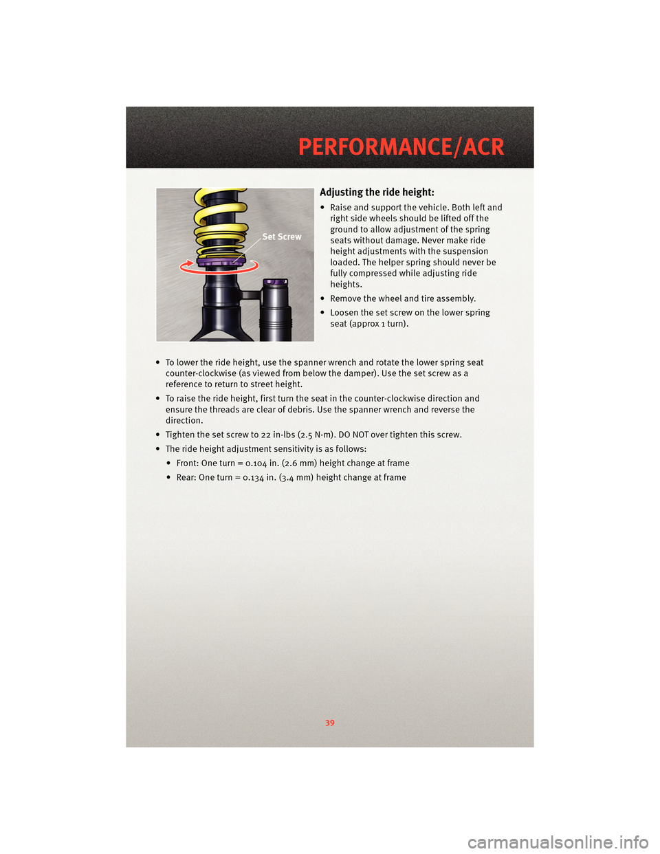
Adjusting the ride height:
• Raise and support the vehicle. Both left andright side wheels should be lifted off the
ground to allow adjustment of the spring
seats without damage. Never make ride
height adjustments with the suspension
loaded. The helper spring should never be
fully compressed while adjusting ride
heights.
• Remove the wheel and tire assembly.
• Loosen the set screw on the lower spring seat (approx 1 turn).
• To lower the ride height, use the spanner wrench and rotate the lower spring seat counter-clockwise (as viewed fr om below the damper). Use the set screw as a
reference to return to street height.
• To raise the ride height, first turn the seat in the counter-clockwise direction and ensure the threads are clear of debris. Use the spanner wrench and reverse the
direction.
• Tighten the set screw to 22 in-lbs (2.5 N·m). DO NOT over tighten this screw.
• The ride height adjustment sensitivity is as follows: • Front: One turn = 0.104 in. (2.6 mm) height change at frame
• Rear: One turn = 0.134 in. (3.4 mm) height change at frame
39
PERFORMANCE/ACR
Page 42 of 80
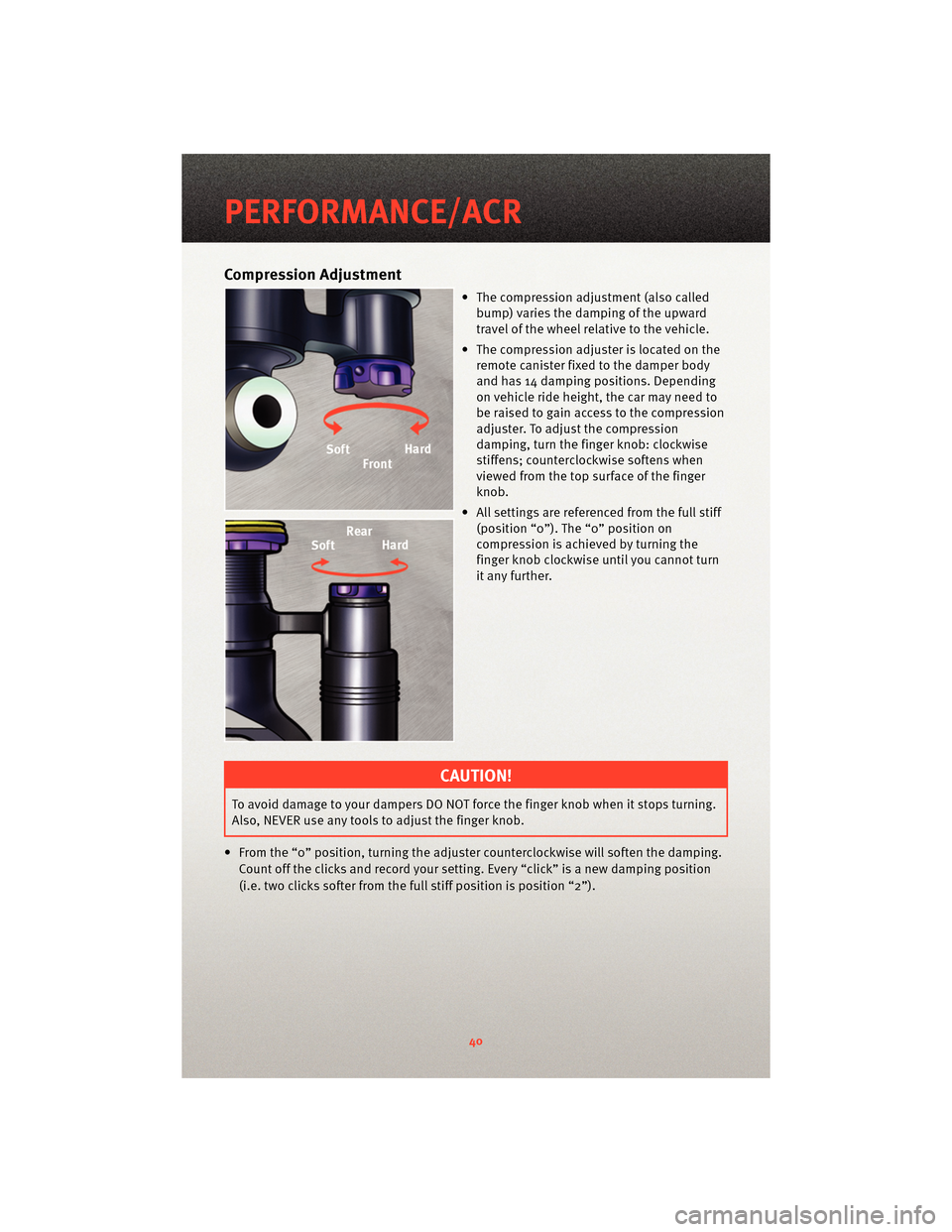
Compression Adjustment
• The compression adjustment (also calledbump) varies the damping of the upward
travel of the wheel relative to the vehicle.
• The compression adjuster is located on the remote canister fixed to the damper body
and has 14 damping positions. Depending
on vehicle ride height, the car may need to
be raised to gain access to the compression
adjuster. To adjust the compression
damping, turn the finge r knob: clockwise
stiffens; counterclockwise softens when
viewed from the top surface of the finger
knob.
• All settings are referenced from the full stiff (position “0”). The “0” position on
compression is achieved by turning the
finger knob clockwise until you cannot turn
it any further.
CAUTION!
To avoid damage to your dampers DO NOT force the finger knob when it stops turning.
Also, NEVER use any tools to adjust the finger knob.
• From the “0” position, turning the adjuster cou nterclockwise will soften the damping.
Count off the clicks and record your setting. Every “click” is a new damping position
(i.e. two clicks softer from the full stiff position is position “2”).
PERFORMANCE/ACR
40
Page 43 of 80
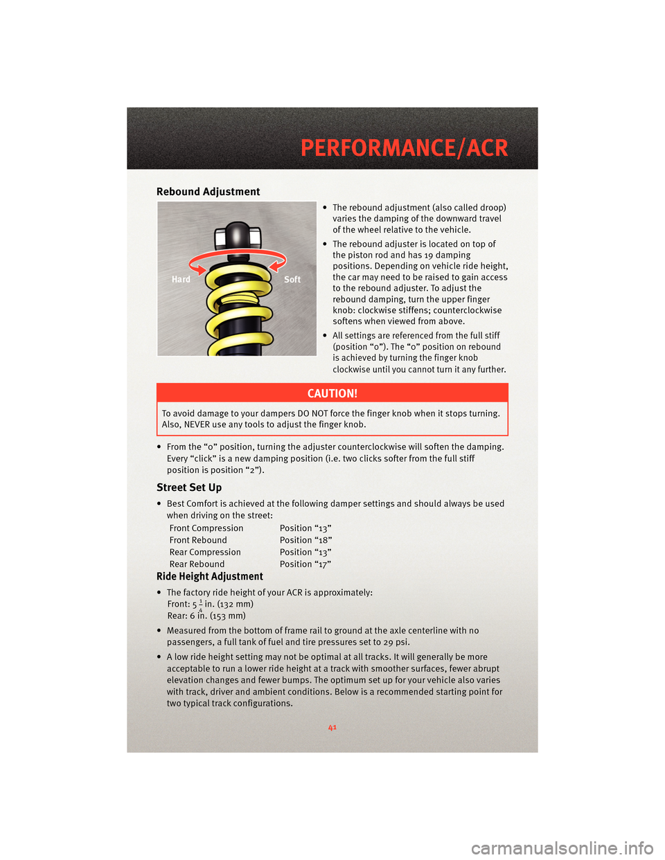
Rebound Adjustment
• The rebound adjustment (also called droop)varies the damping of the downward travel
of the wheel relative to the vehicle.
• The rebound adjuster is located on top of the piston rod and has 19 damping
positions. Depending on vehicle ride height,
the car may need to be raised to gain access
to the rebound adjuster. To adjust the
rebound damping, turn the upper finger
knob: clockwise stiffens; counterclockwise
softens when viewed from above.
•
All settings are referenced from the full stiff
(position “0”). The “0” position on rebound
is achieved by turning the finger knob
clockwise until you cannot turn it any further.
CAUTION!
To avoid damage to your dampers DO NOT force the finger knob when it stops turning.
Also, NEVER use any tools to adjust the finger knob.
• From the “0” position, turning the adjuster cou nterclockwise will soften the damping.
Every “click” is a new damping position (i.e. two clicks softer from the full stiff
position is position “2”).
Street Set Up
• Best Comfort is achieved at the following damper settings and should always be used when driving on the street:
Front Compression Position “13”
Front Rebound Position “18”
Rear Compression Position “13”
Rear Rebound Position “17”
Ride Height Adjustment
• The factory ride height of your ACR is approximately: Front: 514in. (132 mm)
Rear: 6 in. (153 mm)
• Measured from the bottom of frame rail to ground at the axle centerline with no passengers, a full tank of fuel and tire pressures set to 29 psi.
• A low ride height setting may not be optimal at all tracks. It will generally be more acceptable to run a lower ride height at a track with smoother surfaces, fewer abrupt
elevation changes and fewer bumps. The optimum set up for your vehicle also varies
with track, driver and ambient conditions. Below is a recommended starting point for
two typical track configurations.
41
PERFORMANCE/ACR