engine DODGE VIPER 2010 ZB II / 2.G User Guide
[x] Cancel search | Manufacturer: DODGE, Model Year: 2010, Model line: VIPER, Model: DODGE VIPER 2010 ZB II / 2.GPages: 80, PDF Size: 8.08 MB
Page 3 of 80
INTRODUCTION/WELCOME
WELCOME FROM CHRYSLER GROUP
LLC ..................... 2
CONTROLS AT A GLANCE
DRIVER COCKPIT.............. 4
INSTRUMENT CLUSTER ..........6
GETTING STARTED
KEYFOB...................8
MANUAL DOOR LOCK........... 9
THEFT ALARM ................ 9
ENGINE START BUTTON ..........10
SEATBELT .................11
CHILD RESTRAINTS .............11
FRONTSEATS................13
TILT STEERING COLUMN ..........14
ADJUSTABLEPEDALS ...........15
PROGRAMMABLEFEATURES .......16
OPERATING YOUR VEHICLE
TURN SIGNAL/LIGHTS LEVER .......17
WIPER/WASHER LEVER ..........18
MANUAL TRANSMISS ION 1 TO 4 SKIP
SHIFT ....................18
MANUAL CLIMATE CONTROLS .......19
CONVERTIBLE TOP OPERATION ..... 20
WIND BUFFETING ..............21
ELECTRONICS
NON-TOUCH-SCREENRADIO....... 22
NON-TOUCH-SCREENRADIO....... 24
POWER OUTLET..............27
PERFORMANCE/ACR
OVERVIEW ................ 28
AERODYNAMICS............. 29
TWO PIECE BRAKE ROTORS ........34
PILOTSPORTCUPTIRES......... 36
ADJUSTABLE DAMPERS ..........37
HARDCOREPACKAGE ...........43 TUNINGRECORD ..............44
LIMITED WARRANTY
............45
ACKNOWLEDGEMENT .......... 46
WHAT TO DO IN EMERGENCIES
24-HOUR TOWINGASSISTANCE -
U.S. ONLY .................47
INSTRUMENT CLUSTER WARNING
LIGHTS ...................47
IF YOUR ENGINE OVERHEATS .......50
TIREFIT TIRE REPAIR ............51
JUMP-STARTING ..............54
TOWINGADISABLEDVEHICLE.......56
FREEING A STUCK VEHICLE ........57
EVENT DATA RECORDER (EDR) ......58
MAINTAINING YOUR VEHICLE
OPENING THE HOOD............59
ENGINE COMPARTMENT ......... 60
FLUIDS AND CAPACITIES ..........61
MAINTENANCE CHART B ......... 62
FUSES................... 64
TIREPRESSURES..............65
WHEEL AND WHEEL TRIM CARE ..... 66
EXTERIOR BULBS ............. 66
VEHICLESTORAGE .............67
CONSUMER ASSISTANCE
CHRYSLER GROUP LLC CUSTOMER
CENTER.................. 69
CHRYSLER CANADA INC. CUSTOMER
CENTER.................. 69
ASSISTANCE F OR THE HEARING
IMPAIRED................. 69
PUBLICATIONS ORDERING ........ 69
REPORTING SAFETY DEFECTS IN
THE 50 UNITED STATES AND
WASHINGTON, D.C. ............70
TIRE WARRANTY ..............70
MOPAR ACCESSORIES
MOPAR®ACCESSORIES..........73
TABLE OF CONTENTS
Page 8 of 80
INSTRUMENT CLUSTER
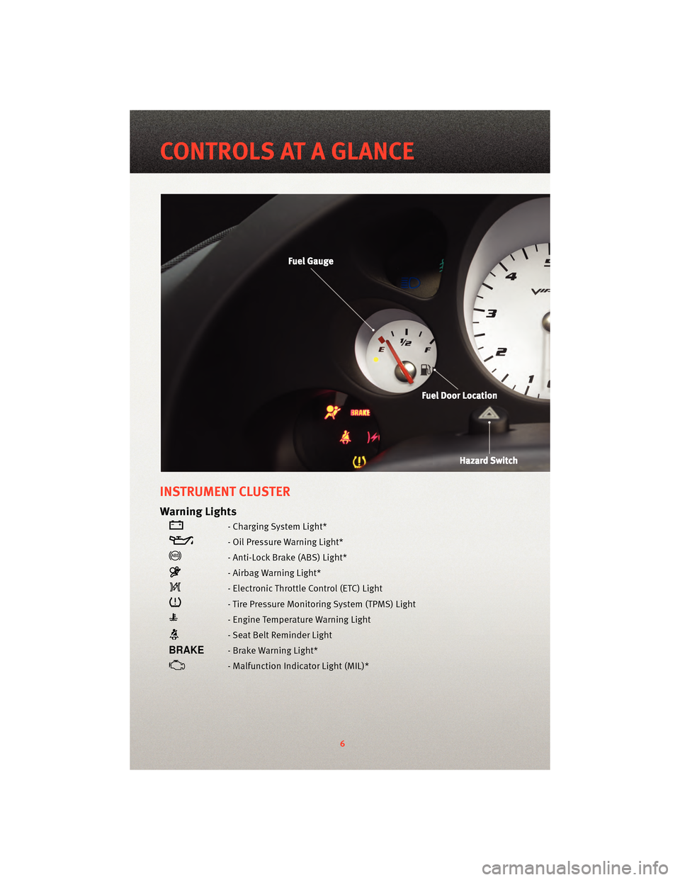
Warning Lights
- Charging System Light*
- Oil Pressure Warning Light*
- Anti-Lock Brake (ABS) Light*
- Airbag Warning Light*
- Electronic Throttle Control (ETC) Light
- Tire Pressure Monitoring System (TPMS) Light
- Engine Temperature Warning Light
- Seat Belt Reminder Light
- Brake Warning Light*
- Malfunction Indicator Light (MIL)*
6
CONTROLS AT A GLANCE
Page 12 of 80
Electronic Immobilization System - Canada Only
• The Electronic Immobilization system prevents unauthorized vehicle operation bydisabling the engine.
• Operation is automatic, regardless of whether the vehicle is locked or unlocked.
• The system will passi vely arm 30 seconds after the key is removed from the vehicle.
• When the system is armed the Vehicle Security Light will flash at a rate of a half-second ON, a half-second OFF, a half-second ON, followed by a 10–second pause
and the vehicle will not start.
• Pressing the Key Fob UNLOCK button will allow the driver 60 seconds to start the
vehicle. Failure to complete the process within 60 seconds will cause the system to
passively re-arm. The driver must repeat the pr ocess again by pressingthe UNLOCK
button on the Key Fob to start the vehicle.
NOTE: Pressing the Key Fob UNLOCK button during the 30 second Electronic
Immobilization arming process will allow the driver 60 seconds to start the vehicle.
ENGINE START BUTTON
Starting
• Fully apply the Parking Brake and press the clutch to the floor.
• Place the Shift Lever in NEUTRAL.
• Insert key into the ignition switch and turn to the ON/RUN position.
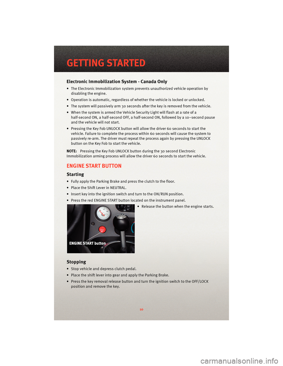
• Press the red ENGINE START button located on the instrument panel.
• Release the button when the engine starts.
Stopping
• Stop vehicle and depress clutch pedal.
• Place the shift lever into gear and apply the Parking Brake.
• Press the key removal release button and turn the ignition switch to the OFF/LOCKposition and remove the key.
GETTING STARTED
10
Page 39 of 80
WARNING!
The Pilot Sport Cup tires were NOT intended to be driven on snow or ice. The Pilot
Sport Cup is a summer season tire and has diminished capability on cold road
surfaces (below 50°F). DO NOT OPERATE THE VEHICLE DURING THESE CONDITIONS.
Snow, ice and cold road surfaces can cause a loss of control or accident.
ADJUSTABLE DAMPERS
• The Viper ACR suspension includes a set of adjustable coil-over racing dampers built
by KW Suspensions. These dampers hav e been tuned by SRT handling engineers to
provide the maximum handling performance without sacrificing reasonable road
manners.
• The two-way adjustable dampers inc lude adjustments for compression (bump) and
rebound damping.
NOTE: Keep your damper settings at the street positions when operating your vehicle on
the street.
WARNING!
Only experienced track drivers should ma ke adjustments to the suspension settings.
Improper suspension adjustment can disrupt the balance of the vehicle and lead to a
loss of control or accident.
CAUTION!
Do not make any adjustments or modifications to the nitrogen pressure of the damper
canisters. This will void the warranty.
• The ACR suspension was designed and tuned with an uncompromising focus on handling. The ride response to road conditions m ay be harsher than expected from a
typical sports car.
37
PERFORMANCE/ACR
Page 50 of 80
CAUTION!
The TPMS has been optimized for the original equipment tires and wheels. TPMS
pressures and warning have been established for the tire size equipped on your
vehicle. Undesirable system operation or sensor damage may result when using
replacement equipment that is not of the same size, type, and/or style. Aftermarket
wheels can cause sensor damage. Do not use tire sealant from a can, or balance
beads if your vehicle is equipped with a TPMS, as damage to the sensors may result.
- Engine Temperature Warning Light
• This light warns of an overheated engine condition.
• If the light turns on and a warning chime sounds while driving, safely pull over andstop the vehicle. If the A/C system is on, t urn it off. Also, shiftthe transmission into
NEUTRAL and idle the vehicle. If the temperat ure reading does not return to normal,
turn the engine off immediately.
• We recommend that you do not operate the vehicle or engine damage will occur. Have the vehicle serviced immediately.
WARNING!
A hot engine cooling system is dangero us. You or others could be badly burned by
steam or boiling coolant. You may want to call an authorized service center for service
if your vehicle overheats.
- Brake Warning Light
• The Brake Warning light illuminates when there is either a system malfunction or the parking brake is applied. If the light is on and the parking brake is not applied, it
indicates a possible brake hydraulic malfunction, brake booster problem or an
Anti-Lock Brake System problem.
• We recommend you drive to the nearest service center and have the vehicle serviced immediately.
WARNING!
Driving a vehicle with the red brake light on is dangerous. Part of the brake system
may have failed. It will take longer to stop the vehicle. You could have an accident.
Have the vehicle checked immediately.
WHAT TO DO IN EMERGENCIES
48
Page 51 of 80
- Malfunction Indicator Light (MIL)
• Certain conditions, such as a loose or missing gas cap,poor fuel quality, etc., may
illuminate the MIL after engine start. The vehicle should be serviced if the light stays
on through several typical driving cycles. In most situations, the vehicle will drive
normally and not require towing.
• If the MIL flashes when the engine is running, serious conditions may exist that could lead to immediate loss of power or severe catalytic converter damage. We recommend
you do not operate the vehicle. Hav e the vehicle serviced immediately.
- Charging System Light
• This light shows the status of the electrical ch arging system. If the charging system
light remains on, it means that the vehicle is experiencing a problem with the charging
system.
• We recommend you do not continue driving if the charging system light is on. Have the vehicle serviced immediately.
- Oil Pressure Warning Light
• This light indicates low engine oil pressure. If the light turns on while driving, stop thevehicle and shut off the engine as soon as possible. A chime will sound for four
minutes when this light turns on.
• We recommend you do not operate the vehicle or engine damage will occur. Have the vehicle serviced immediately.
- Anti-Lock Brake (ABS) Light
• This light monitors the Anti-Lock Brake System (ABS).
• If the light is not on during starting, stays on, or turns on while driving, we recommendyou drive to the nearest service center and have the vehicle serviced immediately.
- Electronic Throttle Control (ETC) Light
• This light informs you of a problem with the Electronic Throttle Control (ETC) system.
• If a problem is detected, the light will come on while the engine is running. Cycle theignition when the vehicle has completely stopped and the shift lever is placed in the
PARK position; the light should turn off.
• If the light remains lit with the engine running, your vehicle will usually be drivable; however, see an authorized service center immediately. If the light is flashing when
the engine is running, immediate service is required and you may experience reduced
performance, an elevated/rough idle or en gine stall and your vehicle may require
towing.
- Airbag Warning Light
• If the light is not on during starting, stays on, or turns on while driving, have the vehicle serviced by an authorized service center immediately.
49
WHAT TO DO IN EMERGENCIES
Page 52 of 80
IF YOUR ENGINE OVERHEATS
• In any of the following situations, you can reduce the potential for overheating by
taking the appropriate action.
• On the highways — slow down.
• In city traffic — while stopped, shift tran smission intoNEUTRAL, but do not increase
engine idle speed.
• In city traffic — while moving, shift into the highest gear possible to reduce engine RPM.
NOTE: There are steps that you can take to slow down an impending overheat
condition:
• If your air conditioner (A/C) is on, turn it off. The A/C system adds heat to the engine cooling system and turning the A/C off can help remove this heat.
• You can also turn the Temperature Control to maximum heat, the Mode Control to floor and the Fan Control to high. This allows the heater core to act as a supplement to the
radiator and aids in removing heat from the engine cooling system.
• If the temperature reading does not re turn to normal, turn the engine off immediately.
• We recommend that you do not operate the vehicle or engine damage will occur. Have the vehicle serviced immediately.
CAUTION!
Driving with a hot cooling system could dama ge your vehicle. If the temperature gauge
reads HOT (H), pull over and stop the vehicle. Idle the vehicle with the air conditioner
turned off until the pointer drops back into the normal range. If the pointer remains on
HOT (H), and you hear continuous chimes, t urn the engine off immediately and call for
service.
WARNING!
You or others can be badly burned by hot engine coolant (antifreeze) or steam from
your radiator. If you see or hear steam coming from under the hood, do not open the
hood until the radiator has had time to co ol. Never try to open a cooling system
pressure cap when the radiator or coolant bottle is hot.
WHAT TO DO IN EMERGENCIES
50
Page 54 of 80
TIREFIT Instructions
• TIREFIT will temporarily seal small punctures up to14in.(6 mm) in the tire tread allowing
you to drive your vehicle up to 100 mi (160 km) with a maximum speed of 55 mph
(90 km/hr). TIREFIT can be used in outside temperatures down to approximately -4°F
(-20°C).
NOTE: Do not remove foreign objects (e.g., screws or nails) from the tire.
• Verify that the valve stem is close to the ground.
• Put on the gloves from the TIREFIT Kit Accessory Storage Compartment.
• Turn the Mode Select knob to the Sealant Mode position
.
• Remove the Yellow Cap from the fitting at the end of the Clear Sealant Hose.
• Remove the valve stem cap and screw the fitting at the end of the Clear Sealant Hose onto the valve stem.
• Insert the Power Plug into the vehicle’s 12-volt power outlet.
• Start the engine and then press the Power button
. The sealant (white fluid) will
flow from the Sealant Bottle through the Clear Sealant Hose and into the tire.
NOTE:
• Sealant may leak out through the puncture in the tire.
• If the sealant (white fluid) does not flow withi n0–10secondsthrough the Clear
Sealant Hose: • Press the Power button
to turn OFF the TIREFIT kit.
• Disconnect the Clear Sealant Hose and make sure the valve stem is free of debris.
• Repeat previous steps to verify sealant will flow, making sure the Mode Select knob is in Sealant Mode
.
• Continue to operate the pump until seal ant is no longer flowing through the hose
(typically takes 30 - 70 seconds). As the sealant flows through the Clear Sealant Hose,
the pressure gauge can read as high as 70 psi. The pressure gauge will decrease
quickly from approximately 70 psi to the actual tire pressure when the sealant bottle is
empty.
• The pump will start to inject air into the tire immediately after the sealant bottle is
empty. Continue to operate the pump and inflate the tire to the pressure indicated on
the Tire and Loading Information label on the driver's side door opening. Check the
tire pressure by looking at the pressure gauge.
NOTE: If the tire does not inflate to at least 26 psi pressure within 15 minutes, the tire is
too badly damaged. Do not attempt to drive the vehicle further. Call for assistance.
• If the tire inflates to the recommended pressure or is at least 26 psi pressure within 15 minutes, press the Power button
to turn off the TIREFIT kit.
• Remove the Speed Limit sticker from the top of the Sealant Bottle and place the sticker on the steering wheel.
• Immediately disconnect the Clear Sealant Ho se from the valve stem, reinstall the
Yellow Cap on the fitting at the end of the hose, and place the TIREFIT kit in the vehicle
storage location. Quickly proceed to the next step.
WHAT TO DO IN EMERGENCIES
52
Page 57 of 80
WARNING!
• Take care to avoid the radiator cooling fan whenever the hood is raised. It can start
anytime the ignition switch is in the ON/RUN position. You can be hurt by the fan.
• Battery fluid is a corrosive acid solution; do not allow battery fluid to contact eyes, skin or clothing. Do not lean over a battery when attaching clamps or allow the
clamps to touch each other. If acid splashes in your eyes or on skin, flush the
contaminated area immediately w ith large quantities of water.
• A battery generates hydrogen gas which is flammable and explosive. Keep flames or sparks away from the battery vent holes. Don’t lean over the battery when
attaching clamps or allow the clamps to touch each other.
• If the vehicle has a discharged battery, booster cables may be used to obtain a start from another vehicle. This type of start can be dangerous if done improperly, so
follow this procedure carefully.
• Do not use a booster battery or any other booster source with an output that exceeds 12-volts (i.e., do not use a 24-volt power source).
• The battery is located underneath an acce ss panel inside the rear compartment on the
left side of the vehicle. A remote batt ery terminal is located in the engine
compartment for jump-starting.
• Remove all metal jewelry, such as watch bands or bracelets, which might make an unintended electrical contact.
WARNING!
Do not permit vehicles to touch each other as this could establish a ground
connection and personal injury could result.
• Park the booster vehicle within cable reach but without letting the vehicles touch. Set the parking brake on both vehicles, shif t the transmissioninto NEUTRAL, and turn the
ignition to LOCK.
• Turn off the heater, radio, and all unnecessary electrical loads.
• Remove the plastic cover from the remote jump-start positive post (+) in the engine compartment.
If You Are Jump-Starting Your Vehicle:
• Connect one end of a jumper cable to the positive (+) terminal on the boosterbattery. Connect the other end of the same cable to the remote jump-start positive
post (+).
• Connect the other cable to the negative terminal on the booster battery. Connect the other end of the same cable to the ear of the thermostat housing on the engine
in your vehicle. Make sure you have a good contact.
55
WHAT TO DO IN EMERGENCIES
Page 58 of 80
If You Are Jump-Starting Another Vehicle:
• Connect one end of a jumper cable to the remote jump-start positive post (+).Connect the other end of the same cable to the positive (+) terminal of the
discharged battery.
• Connect the other cable to the ear of the thermostat housing on the engine in your vehicle. Connect the other end of the same cable to a good ground on the engine in
the other vehicle. Make sure that you have a good contact.
• Start the engine in the vehicle which has the booster battery; let the engine idle a few minutes.
NOTE: The Vehicle Security Alarm System will prevent the engine from starting.
• Turn off the Vehicle Security Alarm System.
• Start the engine in the vehicle with the discha rged battery. If engine does not start in
15 seconds, stop cranking engine and allow s tarter to cool down before cranking
again.
• When removing the jumper cables, reverse the above sequence exactly. Be careful of the moving belts and fan.
WARNING!
During cold weather when temperatures are below the freezingpoint, electrolyte in a
discharged battery may freeze. Do not attempt jump-starting because the battery
could rupture or explode. The battery t emperature must be brought up above the
freezing point before attempting a jump-start.
TOWING A DISABLED VEHICLE
• Do not tow with sling type equipment. Only use flat bed equipment. Always comply
with applicable state or local towing ordinances.
CAUTION!
Towing with equipment other than flat bed types may damage your vehicle.
WHAT TO DO IN EMERGENCIES
56