radio DODGE VIPER 2010 ZB II / 2.G User Guide
[x] Cancel search | Manufacturer: DODGE, Model Year: 2010, Model line: VIPER, Model: DODGE VIPER 2010 ZB II / 2.GPages: 80, PDF Size: 8.08 MB
Page 3 of 80
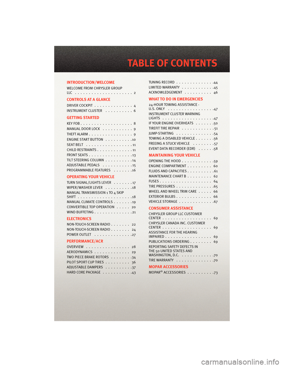
INTRODUCTION/WELCOME
WELCOME FROM CHRYSLER GROUP
LLC ..................... 2
CONTROLS AT A GLANCE
DRIVER COCKPIT.............. 4
INSTRUMENT CLUSTER ..........6
GETTING STARTED
KEYFOB...................8
MANUAL DOOR LOCK........... 9
THEFT ALARM ................ 9
ENGINE START BUTTON ..........10
SEATBELT .................11
CHILD RESTRAINTS .............11
FRONTSEATS................13
TILT STEERING COLUMN ..........14
ADJUSTABLEPEDALS ...........15
PROGRAMMABLEFEATURES .......16
OPERATING YOUR VEHICLE
TURN SIGNAL/LIGHTS LEVER .......17
WIPER/WASHER LEVER ..........18
MANUAL TRANSMISS ION 1 TO 4 SKIP
SHIFT ....................18
MANUAL CLIMATE CONTROLS .......19
CONVERTIBLE TOP OPERATION ..... 20
WIND BUFFETING ..............21
ELECTRONICS
NON-TOUCH-SCREENRADIO....... 22
NON-TOUCH-SCREENRADIO....... 24
POWER OUTLET..............27
PERFORMANCE/ACR
OVERVIEW ................ 28
AERODYNAMICS............. 29
TWO PIECE BRAKE ROTORS ........34
PILOTSPORTCUPTIRES......... 36
ADJUSTABLE DAMPERS ..........37
HARDCOREPACKAGE ...........43 TUNINGRECORD ..............44
LIMITED WARRANTY
............45
ACKNOWLEDGEMENT .......... 46
WHAT TO DO IN EMERGENCIES
24-HOUR TOWINGASSISTANCE -
U.S. ONLY .................47
INSTRUMENT CLUSTER WARNING
LIGHTS ...................47
IF YOUR ENGINE OVERHEATS .......50
TIREFIT TIRE REPAIR ............51
JUMP-STARTING ..............54
TOWINGADISABLEDVEHICLE.......56
FREEING A STUCK VEHICLE ........57
EVENT DATA RECORDER (EDR) ......58
MAINTAINING YOUR VEHICLE
OPENING THE HOOD............59
ENGINE COMPARTMENT ......... 60
FLUIDS AND CAPACITIES ..........61
MAINTENANCE CHART B ......... 62
FUSES................... 64
TIREPRESSURES..............65
WHEEL AND WHEEL TRIM CARE ..... 66
EXTERIOR BULBS ............. 66
VEHICLESTORAGE .............67
CONSUMER ASSISTANCE
CHRYSLER GROUP LLC CUSTOMER
CENTER.................. 69
CHRYSLER CANADA INC. CUSTOMER
CENTER.................. 69
ASSISTANCE F OR THE HEARING
IMPAIRED................. 69
PUBLICATIONS ORDERING ........ 69
REPORTING SAFETY DEFECTS IN
THE 50 UNITED STATES AND
WASHINGTON, D.C. ............70
TIRE WARRANTY ..............70
MOPAR ACCESSORIES
MOPAR®ACCESSORIES..........73
TABLE OF CONTENTS
Page 19 of 80
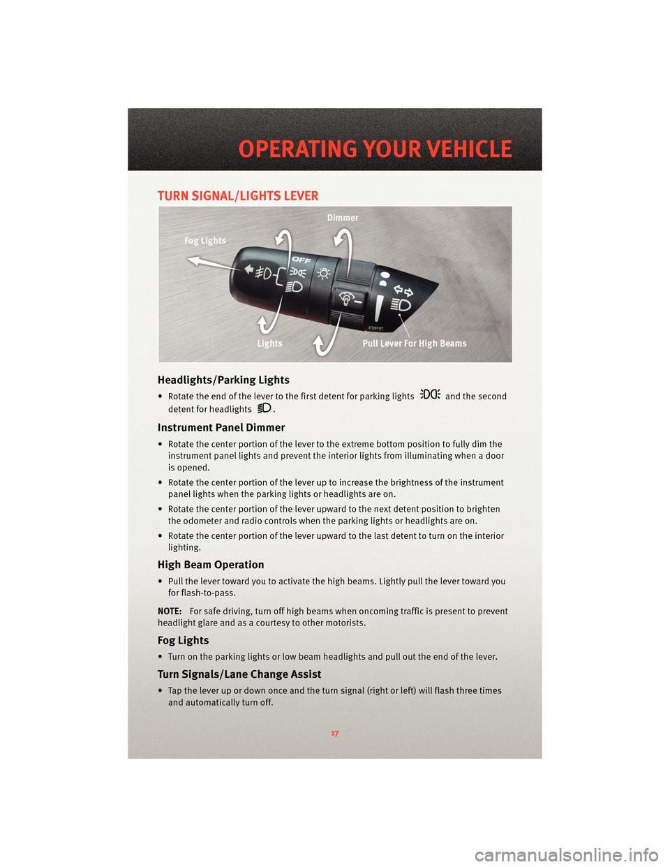
TURN SIGNAL/LIGHTS LEVER
Headlights/Parking Lights
• Rotate the end of the lever to the first detent for parking lightsand the second
detent for headlights
.
Instrument Panel Dimmer
• Rotate the center portion of the lever t o the extreme bottom position to fully dim the
instrument panel lights and prevent the int erior lights from illuminating when a door
is opened.
• Rotate the center portion of the lever up to increase the brightness of the instrument panel lights when the parking lights or headlights are on.
• Rotate the center portion of the lever u pward to the next detent position to brighten
the odometer and radio controls when the parking lights or headlights are on.
• Rotate the center portion of the lever upward to the last detent to turn on the interior lighting.
High Beam Operation
• Pull the lever toward you to activate the high beams. Lightly pull the lever toward youfor flash-to-pass.
NOTE: For safe driving, turn off high beams when oncoming traffic is present to prevent
headlight glare and as a courtesy to other motorists.
Fog Lights
• Turn on the parking lights or low beam headlights and pull out the end of the lever.
Turn Signal s/Lane Change Assist
• Tap the lever up or down once and the turn signal (right or left) will flash three times
and automatically turn off.
17
OPERATING YOUR VEHICLE
Page 24 of 80
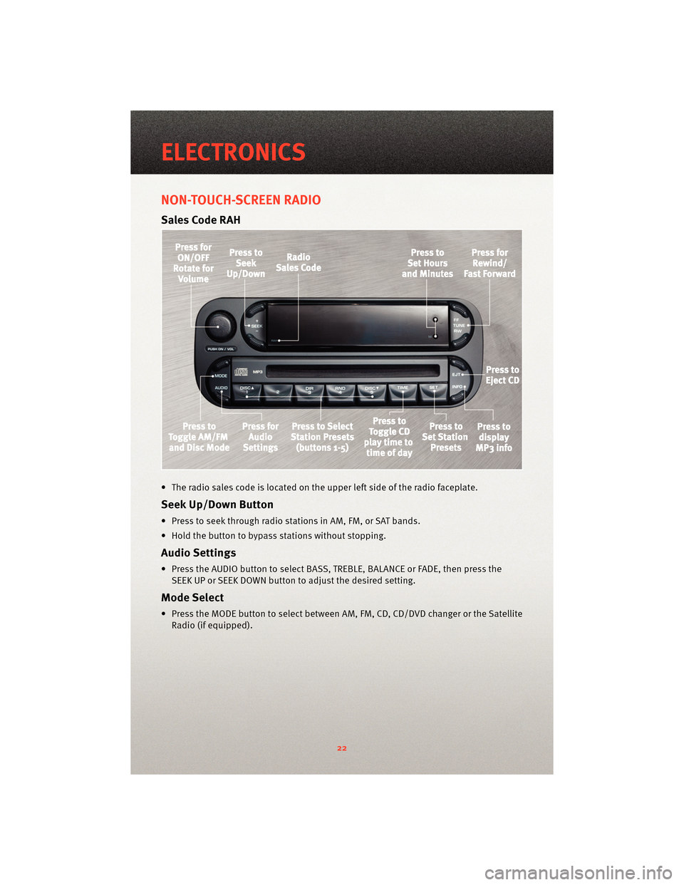
NON-TOUCH-SCREEN RADIO
Sales Code RAH
• The radio sales code is located on the upper left side of the radio faceplate.
Seek Up/Down Button
• Press to seek through radio stations in AM, FM, or SAT bands.
• Hold the button to bypass stations without stopping.
Audio Settings
• Press the AUDIO button to select BASS, TREBLE, BALANCE or FADE, then press theSEEK UP or SEEK DOWN button to adjust the desired setting.
Mode Select
• Press the MODE button to select between AM, FM, CD, CD/DVD changer or the Satellite
Radio (if equipped).
ELECTRONICS
22
Page 25 of 80
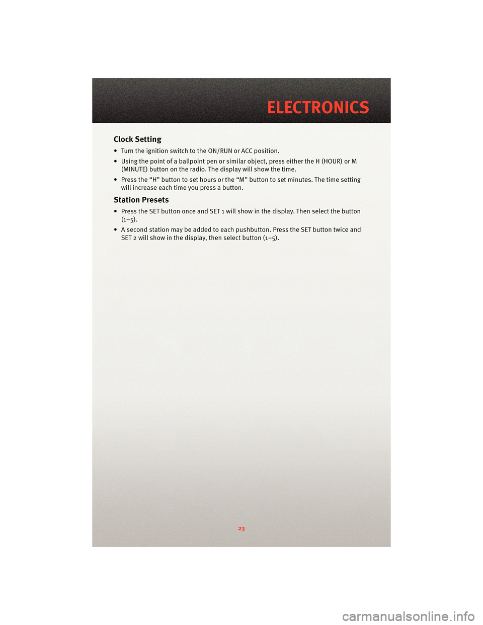
Clock Setting
• Turn the ignition switch to the ON/RUN or ACC position.
• Using the point of a ballpoint pen or similar object, press either the H (HOUR) or M(MINUTE) button on the radio. The display will show the time.
• Press the “H” button to set hours or the “M” button to set minutes. The time setting
will increase each time you press a button.
Station Presets
• Press the SET button once and SET 1 will show in the display. Then select the button (1–5).
• A second station may be added to each pushbutton. Press the SET button twice and SET 2 will show in the display, then select button (1–5).
23
ELECTRONICS
Page 26 of 80
NON-TOUCH-SCREEN RADIO
Navigation Radio – RB1
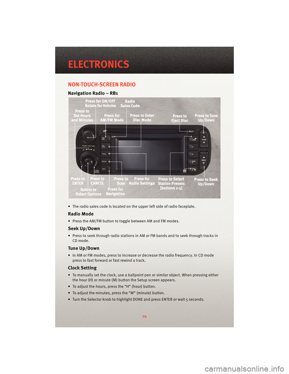
• The radio sales code is located on the upper left side of radio faceplate.
Radio Mode
• Press the AM/FM button to toggle between AM and FM modes.
Seek Up/Down
• Press to seek through radio stations in AM or FM bands and to seek through tracks inCD mode.
Tune Up/Down
• In AM or FM modes, press to increase or decrease the radio frequency. In CD modepress to fast forward or fast rewind a track.
Clock Setting
• To manually set the clock, use a ballpoint pen or similar object. When pressing eitherthe hour (H) or minute (M) button the Setup screen appears.
• To adjust the hours, press the “H” (hour) button.
• To adjust the minutes, press the “M” (minute) button.
• Turn the Selector knob to highlight DONE and press ENTER or wait 5 seconds.
ELECTRONICS
24
Page 27 of 80
Daylight Savings
• Use a ball point pen or similar object to press the "H" (hour) or "M" (Minute) button toaccess the clock setup screen.
• Press ENTER to select Clock Setup.
• Rotate the Selector knob to highlight Daylight Savings and press ENTER.
• Rotate the Selector knob to highlight St andard or Daylight Savings and press ENTER.
• Turn the Selector knob to highlight DONE and press ENTER or wait 5 seconds.
Changing Time Zone
• Use a ball point pen or similar object to press the "H" (hour) or "M" (Minute) button to access the clock setup screen.
• Press ENTER to select Clock Setup.
• Rotate the Selector knob to highlight Time Zone and press ENTER.
• Rotate the Selector knob to highlight the desired Time Zone and press ENTER.
• Turn the Selector knob to highlight DONE and press ENTER or wait 5 seconds.
Store Radio Presets
• Find the station to store by either pressing the seek up/down button, the tune up/down button, or by t ouching the SCAN button.
• Turn the Selector knob to highlight SET and press ENTER. SET 1 appears on the display.
• Then select button (1–5).
• You may add a second station to each pushb utton by repeating the above procedure
with this exception: After highlighting SET, press ENTER twice. SET 2 appears on the
display, then select button (1–5).
Navigation
Navigation Radio – RB1 Only
• Your navigation system receives GPS signals from up to 8 satellites to display the position and direction of your vehicle.
• Map and database information is supplied through a DVD-ROM and vehicle sensors enable the system to display the present vehicle position even in locations where GPS
may be blocked.
• The DVD-ROM disc must be inserted into the radio before accessing the Navigation mode.
NOTE: Many features of this radio are speed dependent. For your own safety, some of
the programmable options will be grayed out and unavailable while the vehicle is in
motion. Pull over at a safe location to complete your task.
New Destination
• Press the NAV button to access the NAV Main Menu.
• Using the Selector knob, highlight Destination to program a destination, press ENTER, then select one of the 8 ways to input a destination.
25
ELECTRONICS
Page 28 of 80
Program Destination by Street Address
• Press the NAV button to access the NAV Main Menu.
• Select/highlight Destination from the Main Menu screen and press ENTER.
• Select/highlight Street Address from the Find Destination by screen and press ENTER.
• Select/highlight Street Name from the Find Address screen and press ENTER.
NOTE: City, State and Province can be also be changed in the Find Address screen.
• The Input Street Name screen appears. Use the Selector knob to spell out the street
name. Select/highlight each letter and press ENTER.
• Select/highlight Street List and press ENTER to continue. The Select Street Name screen appears. Select/highlight the c orrect street and press ENTER.
• The Input Address screen appears. Us e the Selector knob to input the address
number. When finished, select/highlight Done and press ENTER.
• Lastly, the Confirm Destination screen appe ars, showing the address of the selected
destination. If it is correct, select/highlight OK and press ENTER. The system will
calculate a route to that destination.
Address Book
• Press the NAV button, use the Selector knob to highlight Destination and press ENTER.
• Select/highlight one of the eight choices to input a destination and press ENTER.
• Enter the address information following the screen prompts.
• Once a destination has been entered, select/highlight Options from the Confirm Destination screen and press ENTER.
• Select/Highlight Save in Address Book and press ENTER.
• The Input Name screen appears. Use the Select Encoder to spell out the name you
would like to see in the Address Book.
• Select/highlight Done when finished and press ENTER.
• The Input Phone Number screen appears. Use the Select Encoder to input the phone
number of the address. When the number is complete, or if you do not know the
phone number, select/highlight Save and press ENTER.
• The name, address and phone number are now stored in the address book. The Confirm Destination screen will reappear showing the saved information.
Map
• Press the NAV button and select/highlight Map and press ENTER.
• The Map screen will appear showing your current location.
Adjusting Navigation Volume
• The navigation volume can be adjusted during a voice command by using the radioPower/Volume control knob.
• To repeat a voice command select the voice icon on the Map or Arrow guidance.
ELECTRONICS
26
Page 45 of 80
HARD CORE PACKAGE
• This option is for the Hard Core track enthusiast who is looking for maximum weight
savings.
• The Hard Core Package eliminates the Audio System (including the radio, amplifier,
door speakers and subwoofer). Also delet ed are the under hood silencer pad, the
trunk carpet and the tire inflator. The door speakers are replaced by carbon fiber
panels. The radio is replaced by a lightweight cover that can be configured to mount
the included Lap Timer.
CAUTION!
The tire inflator has been removed from the Hard Core package. There are no
measures for flat tire repair included with this vehicle. It is recommended that drivers
always bring a mobile phone in case of a flat tire.
• The removal of the trunk carpeting reduces sound insulation. It is normal to hear more road and drivetrain noise.
• The Lap Timer kit includes the Timer, Beacon Receiver, a power cord, download kit and the Beacon Transmitter.
• The Lap Timer displays lap times on a large illuminated digital display. It continuously updates the fastest laps and acquires a running data log of all times during the track
event. This data can be do wnloaded for analysis via a USB connection. Refer to your
AiM lap timer manual for instructions.
• The cables to the beacon receiver and power jack include extra long lengths. This is to provide the ability to custom fit the timer and beacon receiver depending on the track
and/or driver preference.
• Note on Lap Timer: For lap timer software updates and technical support contact www.aimsports.com/software/index.html.
43
PERFORMANCE/ACR
Page 57 of 80
WARNING!
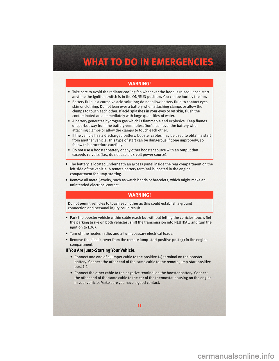
• Take care to avoid the radiator cooling fan whenever the hood is raised. It can start
anytime the ignition switch is in the ON/RUN position. You can be hurt by the fan.
• Battery fluid is a corrosive acid solution; do not allow battery fluid to contact eyes, skin or clothing. Do not lean over a battery when attaching clamps or allow the
clamps to touch each other. If acid splashes in your eyes or on skin, flush the
contaminated area immediately w ith large quantities of water.
• A battery generates hydrogen gas which is flammable and explosive. Keep flames or sparks away from the battery vent holes. Don’t lean over the battery when
attaching clamps or allow the clamps to touch each other.
• If the vehicle has a discharged battery, booster cables may be used to obtain a start from another vehicle. This type of start can be dangerous if done improperly, so
follow this procedure carefully.
• Do not use a booster battery or any other booster source with an output that exceeds 12-volts (i.e., do not use a 24-volt power source).
• The battery is located underneath an acce ss panel inside the rear compartment on the
left side of the vehicle. A remote batt ery terminal is located in the engine
compartment for jump-starting.
• Remove all metal jewelry, such as watch bands or bracelets, which might make an unintended electrical contact.
WARNING!
Do not permit vehicles to touch each other as this could establish a ground
connection and personal injury could result.
• Park the booster vehicle within cable reach but without letting the vehicles touch. Set the parking brake on both vehicles, shif t the transmissioninto NEUTRAL, and turn the
ignition to LOCK.
• Turn off the heater, radio, and all unnecessary electrical loads.
• Remove the plastic cover from the remote jump-start positive post (+) in the engine compartment.
If You Are Jump-Starting Your Vehicle:
• Connect one end of a jumper cable to the positive (+) terminal on the boosterbattery. Connect the other end of the same cable to the remote jump-start positive
post (+).
• Connect the other cable to the negative terminal on the booster battery. Connect the other end of the same cable to the ear of the thermostat housing on the engine
in your vehicle. Make sure you have a good contact.
55
WHAT TO DO IN EMERGENCIES
Page 71 of 80
CHRYSLER GROUP LLC
CUSTOMER CENTER
P.O. Box 21–8004
Auburn Hills, MI 48321–8004
Phone: 1–800–423–6343
CHRYSLER CANADA INC.
CUSTOMER CENTER
P.O. Box 1621
Windsor, Ontario N9A 4H6
Phone: 1–800–465–2001
ASSISTANCE FOR THE
HEARING IMPAIRED
• To assist customers who have hearingdifficulties, the manufacturer has
installed special TDD
(Telecommunication Devices for the
Deaf) equipment at its customer
center. Any hearing or speech
impaired customer, who has access to
a TDD or a conventional teletypewriter
(TTY) in the United States, can
communicate with the manufacturer
by dialing 1–800–380–CHRY.
Canadian residents with hearing
difficulties that requir e assistance can
use the special needs relay service
offered by Bell Canada. For TTY
teletypewriter users, dial 711 and for
Voice callers, dial 1–800–855–0511 to
connect with a Bell Relay Service
operator.
WARNING!
Engine exhaust, some of its
constituents, and certain vehicle
components contain, or emit,
chemicals known to the State of
California to cause cancer and birth
defects, or other reproductive harm.
In addition, certain fluids contained
in vehicles and certain products of
component wear contain, or emit,
chemicals known to the State of
California to cause cancer and birth
defects, or other reproductive harm.
PUBLICATIONS ORDERING
• If you are the first registered retail
owner of your vehicle, you may obtain
one free printed copy of the Owner's
Manual, Warranty Booklet or Radio
Manuals on your DVD by calling
1–800–423–6343 (U.S.) or
1–800–387–1143 (Canada) or by
contacting your dealer.
• Replacement User Guides or DVDs or, if you prefer, additional printed
copies of the Owner's Manual,
Warranty Booklet or Radio Manuals
may be purchased by visiting
www.techauthority.com or by calling
1–800–890–4038 (U.S.) or
1–800–387–1143 (Canada). Visa,
Master Card, American Express and
Discover orders are accepted. If you
prefer mailing your order, please call
the above numbers for an order form.
NOTE: A street address is required
when ordering manuals (no P.O. Boxes).
69
CONSUMER ASSISTANCE