stop start DODGE VIPER 2010 ZB II / 2.G User Guide
[x] Cancel search | Manufacturer: DODGE, Model Year: 2010, Model line: VIPER, Model: DODGE VIPER 2010 ZB II / 2.GPages: 80, PDF Size: 8.08 MB
Page 12 of 80
Electronic Immobilization System - Canada Only
• The Electronic Immobilization system prevents unauthorized vehicle operation bydisabling the engine.
• Operation is automatic, regardless of whether the vehicle is locked or unlocked.
• The system will passi vely arm 30 seconds after the key is removed from the vehicle.
• When the system is armed the Vehicle Security Light will flash at a rate of a half-second ON, a half-second OFF, a half-second ON, followed by a 10–second pause
and the vehicle will not start.
• Pressing the Key Fob UNLOCK button will allow the driver 60 seconds to start the
vehicle. Failure to complete the process within 60 seconds will cause the system to
passively re-arm. The driver must repeat the pr ocess again by pressingthe UNLOCK
button on the Key Fob to start the vehicle.
NOTE: Pressing the Key Fob UNLOCK button during the 30 second Electronic
Immobilization arming process will allow the driver 60 seconds to start the vehicle.
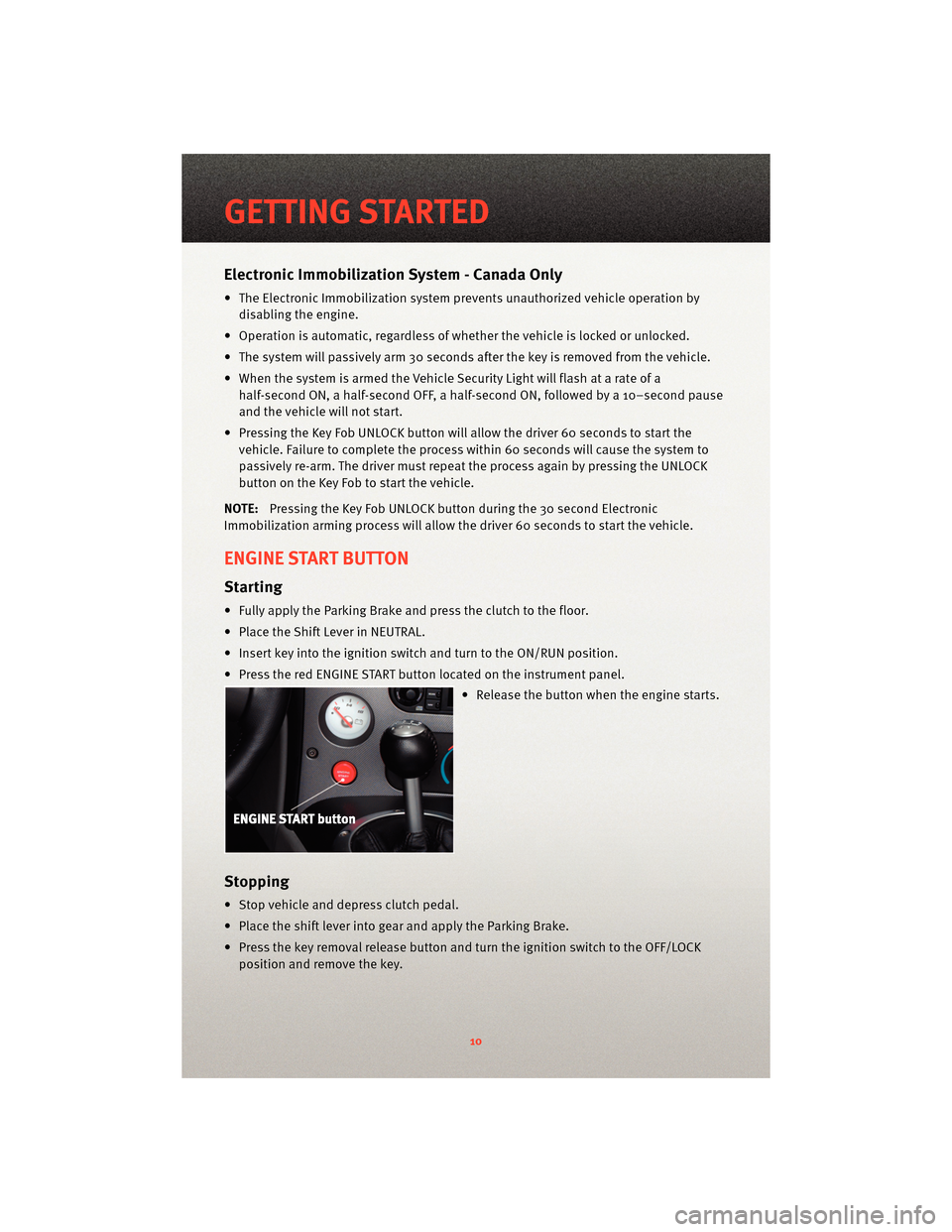
ENGINE START BUTTON
Starting
• Fully apply the Parking Brake and press the clutch to the floor.
• Place the Shift Lever in NEUTRAL.
• Insert key into the ignition switch and turn to the ON/RUN position.
• Press the red ENGINE START button located on the instrument panel.
• Release the button when the engine starts.
Stopping
• Stop vehicle and depress clutch pedal.
• Place the shift lever into gear and apply the Parking Brake.
• Press the key removal release button and turn the ignition switch to the OFF/LOCKposition and remove the key.
GETTING STARTED
10
Page 17 of 80
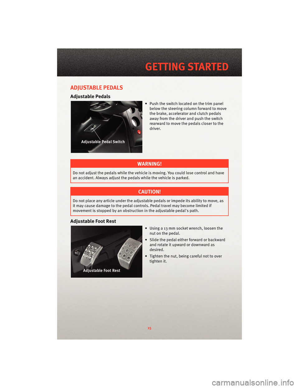
ADJUSTABLE PEDALS
Adjustable Pedals
• Push the switch located on the trim panelbelow the steering column forward to move
the brake, accelerator and clutch pedals
away from the driver and push the switch
rearward to move the pedals closer to the
driver.
WARNING!
Do not adjust the pedals while the vehicle is moving. You could lose control and have
an accident. Always adjust the pedals while the vehicle is parked.
CAUTION!
Do not place any article under the adjustable pedals or impede its ability to move, as
it may cause damage to the pedal controls. Pedal travel may become limited if
movement is stopped by an obstruction in the adjustable pedal's path.
Adjustable Foot Rest
• Using a 13 mm socket wrench, loosen the
nut on the pedal.
• Slide the pedal either forward or backward and rotate it upward or downward as
desired.
• Tighten the nut, being careful not to over tighten it.
15
GETTING STARTED
Page 37 of 80
Alternate Break in Procedure
CAUTION!
Chrysler does not endorse speeding on public roads; therefore, if a safe area cannot
be used for break-in, you must perform the street break-in procedure. Regardless of
completing the “street brea k-in procedure,” this alternative break-in procedure is
recommended before any track use of the vehicle.
• In the event that the street break-in procedure can’t be performed before the pads and
rotors are thermally stressed, use the following procedure:
• Read through the procedure and find a suitab le, safe and legal area to perform the
necessary stops.
• BEFORE starting the break-in procedure, drive with gentle braking. Do not use
brakes aggressively until performing brake-in procedure.
• Make a series of 10 stops from 60 to 5-10 MPH. At the end of each stop, immediately accelerate to 60 again for the next stop. Run all stops continuously in
one cycle.
NOTE: A moderate braking effort is needed to properly break in the rotors and pads. A
stopping force of approxim ately 0.8G’s, just short of ABS intervention, is the level of
pedal effort you are trying to attain.
• During the 60 to 5-10 MPH series of stops, the exact speed is not critical. Accelerateto approximately 60 and begin the brak ing cycle. As you approach 5-10 MPH, it is
not necessary to watch the speedometer. Keep your eyes on the road and
approximate your speed at the end of each cycle.
CAUTION!
Do not come to a complete stop! This will imprint pad material onto the rotor, causing
a vibration during future use.
• Watch for the following:
• On the 8th or 9th stop, there should be a distinct smell from the brakes. Smoke may be evident during earlier stops as well.
• Also on the 8th or 9th stop, some friction materials will experience “green fade”. This is a slight fading of the brakes. The fade will
stabilize, but not completely go away until the brakes have cooled.
• After the break-in cycle is finished there will be a light gray film on the rotor face. The gray film is pad material starting to transfer onto the
rotor face.
35
PERFORMANCE/ACR
Page 38 of 80
CAUTION!
Do not come to a complete stop when the system is hot and leave your foot on the
pedal. Pad material will immediately transfer to the rotor causing a vibration during
future use.
• After the final stop, drive as much as possible without using the brakes to cool off the system. Ideally, the brakes should be allowed to cool to ambient temperature
before using them again.
• After the first break in cycle, the brakes will still not be operating at optimum capacity. A second or third heat cycle is typically necessary before the brakes start
to work optimally. This will occur during everyday use.
Care and Maintenance
• Your brake calipers have a painted finish. Immedi ately clean off any spilled brake
fluid, wiping it off with a soft, clean terry-cloth towel.
• Do not use any harsh chemicals when cleaning your calipers. Wash your calipers with soap and rinse with water.
• Do not use any harsh chemicals when cleaning your rotor hats (the anodized center part of the rotor assembly). Wash your rotor hats with soap and rinse with water.
• Breaking-in rotors and pads is critical to the optimum performance of your new brakes. When breaking-in new parts, you are not only heat-cycling the pads, you are
also depositing a layer of pad material onto the rotor face. If not broken-in properly, an
uneven layer of pad material will be deposited onto the rotor, causing vibration.
• If you experience brake pedal pulsation, steering vibration, or repeatable brake noise, perform the break-in procedure again as soon as possible. This will re-condition the
rotor surface and remove irregular brake pad deposits. If concerns continue, please
visit y our local dealer fo r further diagnosis.
PILOT SPORT CUP TIRES
• Your Viper ACR comes equipped with Michelin Pilot Sport Cup competition oriented
tires that are DOT approved for street use. The Pilot Sport Cup tire uses a special tread
and compound which provides considerably more dry grip than normal street tires.
• Due to the special tread and compound of your Pilot Sport Cup Tires, the minimum tread depth can be reached earlier dependin g on your driving style, resulting in
reduced tire life. The special Pilot S port Cup tread and compound may lead to
performance degradation in cold climates, heavy rain or in conditions with standing
water.
WARNING!
Use extreme caution and drive slowly in wet situations to reduce the risk of
hydroplaning. Avoid driving in any conditions of heavy rain or standing water. These
conditions can cause loss of control or accident.
PERFORMANCE/ACR
36
Page 43 of 80
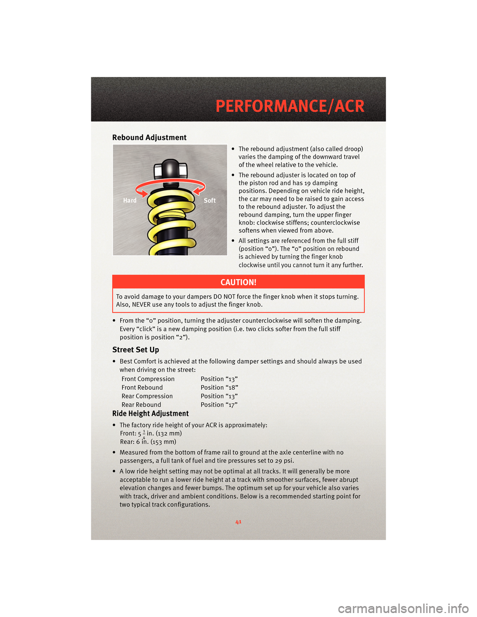
Rebound Adjustment
• The rebound adjustment (also called droop)varies the damping of the downward travel
of the wheel relative to the vehicle.
• The rebound adjuster is located on top of the piston rod and has 19 damping
positions. Depending on vehicle ride height,
the car may need to be raised to gain access
to the rebound adjuster. To adjust the
rebound damping, turn the upper finger
knob: clockwise stiffens; counterclockwise
softens when viewed from above.
•
All settings are referenced from the full stiff
(position “0”). The “0” position on rebound
is achieved by turning the finger knob
clockwise until you cannot turn it any further.
CAUTION!
To avoid damage to your dampers DO NOT force the finger knob when it stops turning.
Also, NEVER use any tools to adjust the finger knob.
• From the “0” position, turning the adjuster cou nterclockwise will soften the damping.
Every “click” is a new damping position (i.e. two clicks softer from the full stiff
position is position “2”).
Street Set Up
• Best Comfort is achieved at the following damper settings and should always be used when driving on the street:
Front Compression Position “13”
Front Rebound Position “18”
Rear Compression Position “13”
Rear Rebound Position “17”
Ride Height Adjustment
• The factory ride height of your ACR is approximately: Front: 514in. (132 mm)
Rear: 6 in. (153 mm)
• Measured from the bottom of frame rail to ground at the axle centerline with no passengers, a full tank of fuel and tire pressures set to 29 psi.
• A low ride height setting may not be optimal at all tracks. It will generally be more acceptable to run a lower ride height at a track with smoother surfaces, fewer abrupt
elevation changes and fewer bumps. The optimum set up for your vehicle also varies
with track, driver and ambient conditions. Below is a recommended starting point for
two typical track configurations.
41
PERFORMANCE/ACR
Page 49 of 80
24-HOUR TOWING ASSISTANCE - U.S. ONLY
• Dial toll-free 1-800-521-2779 or 1-800-363-4869 for Canadian residents.
• Provide your name, vehicle identification number and license plate number.
• Provide your location, including telephone number, from which you are calling.
• Briefly describe the nature of the problem and answer a few simple questions.
• You will be given the name of the service provider and an estimated time of arrival. Ifyou feel you are in an “unsafe situation”, please let us know. With your consent, we
will contact local police or safety authorities.
INSTRUMENT CLUSTER WARNING LIGHTS
- Tire Pressure Monitoring System (TPMS) Light
• Each tire, including the spare (if provided), should be checked monthly, when coldand inflated to the inflation pressure recommended by the vehicle manufacturer on
the vehicle placard or tire inflation pressure label. (If your vehicle has tires of a
different size than the size indicated on the v ehicle placard or tire inflation pressure
label, you should determine the proper tire inflation pressure for those tires.)
• As an added safety feature, your vehicle has been equipped with a Tire Pressure Monitoring System (TPMS) that illuminates a low tire pressure telltale when one or
more of your tires is significantly under-inflat ed. Accordingly, when the low tire
pressure telltale illuminates, you should stop and check your tires as soon as
possible, and inflate them to the proper pressure. Driving on a significantly
under-inflated tire causes the tire to overheat and can lead to tire failure.
Under-inflation also reduces fuel efficiency and tire tread life, and may affect the
vehicle’s handling and stopping ability.
• Please note that the TPMS is not a subs titute for proper tire maintenance, and it is the
driver’s responsibility to maintain correct tire pressure, even if under-inflation has not
reached the level to trigger illumination of the TPMS low tire pressure telltale.
• Your vehicle has also been equipped with a TPMS malfunction indicator to indicate
when the system is not operating properly. The TPMS malfunction indicator is
combined with the low tire pressure telltale. When the system detects a malfunction,
the telltale will flash for approximately one minute and then remain continuously
illuminated. This sequence will continue upon subsequent vehicle start-ups as long as
the malfunction exists.
• When the malfunction indicator is illuminated, the system may not be able to detect or signal low tire pressure as intended. TPMS malfunctions may occur for a variety of
reasons, including the installation of replacement or alternate tires or wheels on the
vehicle that prevent the TPMS from functioning properly. Always check the TPMS
malfunction telltale after replacing one or more tires or wheels on your vehicle, to
ensure that the replacement or alternate tires and wheels allow the TPMS to continue
to function properly.
47
WHAT TO DO IN EMERGENCIES
Page 51 of 80
- Malfunction Indicator Light (MIL)
• Certain conditions, such as a loose or missing gas cap,poor fuel quality, etc., may
illuminate the MIL after engine start. The vehicle should be serviced if the light stays
on through several typical driving cycles. In most situations, the vehicle will drive
normally and not require towing.
• If the MIL flashes when the engine is running, serious conditions may exist that could lead to immediate loss of power or severe catalytic converter damage. We recommend
you do not operate the vehicle. Hav e the vehicle serviced immediately.
- Charging System Light
• This light shows the status of the electrical ch arging system. If the charging system
light remains on, it means that the vehicle is experiencing a problem with the charging
system.
• We recommend you do not continue driving if the charging system light is on. Have the vehicle serviced immediately.
- Oil Pressure Warning Light
• This light indicates low engine oil pressure. If the light turns on while driving, stop thevehicle and shut off the engine as soon as possible. A chime will sound for four
minutes when this light turns on.
• We recommend you do not operate the vehicle or engine damage will occur. Have the vehicle serviced immediately.
- Anti-Lock Brake (ABS) Light
• This light monitors the Anti-Lock Brake System (ABS).
• If the light is not on during starting, stays on, or turns on while driving, we recommendyou drive to the nearest service center and have the vehicle serviced immediately.
- Electronic Throttle Control (ETC) Light
• This light informs you of a problem with the Electronic Throttle Control (ETC) system.
• If a problem is detected, the light will come on while the engine is running. Cycle theignition when the vehicle has completely stopped and the shift lever is placed in the
PARK position; the light should turn off.
• If the light remains lit with the engine running, your vehicle will usually be drivable; however, see an authorized service center immediately. If the light is flashing when
the engine is running, immediate service is required and you may experience reduced
performance, an elevated/rough idle or en gine stall and your vehicle may require
towing.
- Airbag Warning Light
• If the light is not on during starting, stays on, or turns on while driving, have the vehicle serviced by an authorized service center immediately.
49
WHAT TO DO IN EMERGENCIES
Page 58 of 80
If You Are Jump-Starting Another Vehicle:
• Connect one end of a jumper cable to the remote jump-start positive post (+).Connect the other end of the same cable to the positive (+) terminal of the
discharged battery.
• Connect the other cable to the ear of the thermostat housing on the engine in your vehicle. Connect the other end of the same cable to a good ground on the engine in
the other vehicle. Make sure that you have a good contact.
• Start the engine in the vehicle which has the booster battery; let the engine idle a few minutes.
NOTE: The Vehicle Security Alarm System will prevent the engine from starting.
• Turn off the Vehicle Security Alarm System.
• Start the engine in the vehicle with the discha rged battery. If engine does not start in
15 seconds, stop cranking engine and allow s tarter to cool down before cranking
again.
• When removing the jumper cables, reverse the above sequence exactly. Be careful of the moving belts and fan.
WARNING!
During cold weather when temperatures are below the freezingpoint, electrolyte in a
discharged battery may freeze. Do not attempt jump-starting because the battery
could rupture or explode. The battery t emperature must be brought up above the
freezing point before attempting a jump-start.
TOWING A DISABLED VEHICLE
• Do not tow with sling type equipment. Only use flat bed equipment. Always comply
with applicable state or local towing ordinances.
CAUTION!
Towing with equipment other than flat bed types may damage your vehicle.
WHAT TO DO IN EMERGENCIES
56
Page 67 of 80
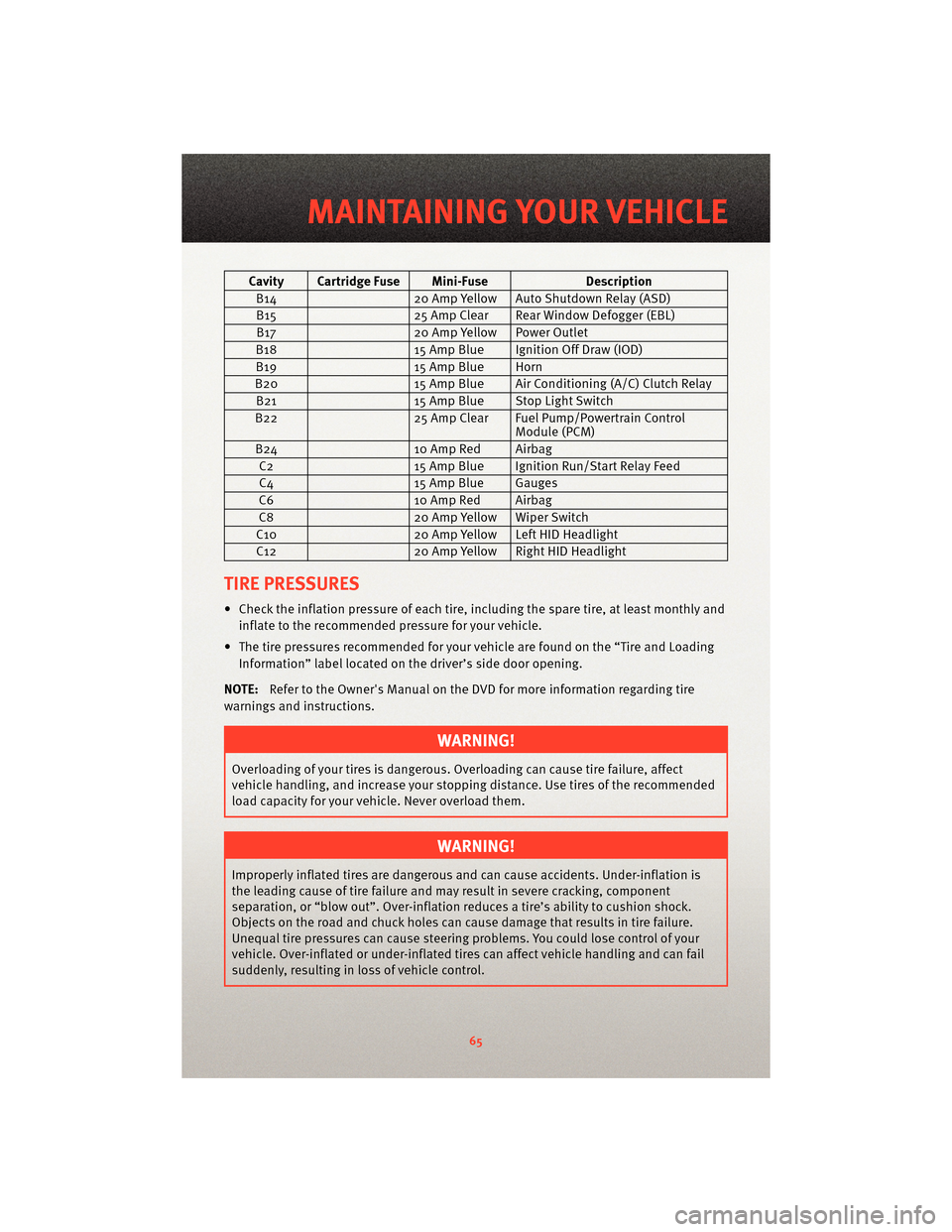
Cavity Cartridge Fuse Mini-FuseDescription
B14 20 Amp Yellow Auto Shutdown Relay (ASD)
B15 25 Amp Clear Rear Window Defogger (EBL)
B17 20 Amp Yellow Power Outlet
B18 15 Amp Blue Ignition Off Draw (IOD)
B19 15 Amp Blue Horn
B20 15 Amp Blue Air Conditioning (A/C) Clutch Relay
B21 15 Amp Blue Stop Light Switch
B22 25 Amp Clear Fuel Pump/Powertrain Control
Module (PCM)
B24 10 Amp Red Airbag
C2 15 Amp Blue Ignition Run/Start Relay Feed
C4 15 Amp Blue Gauges
C6 10 Amp Red Airbag
C8 20 Amp Yellow Wiper Switch
C10 20 Amp Yellow Left HID Headlight
C12 20 Amp Yellow Right HID Headlight
TIRE PRESSURES
• Check the inflation pressure of each tire, including the spare tire, at least monthly and
inflate to the recommended pressure for your vehicle.
• The tire pressures recommended for your vehicle are found on the “Tire and Loading Information” label located on the driver’s side door opening.
NOTE: Refer to the Owner's Manual on the DVD f or more information regarding tire
warnings and instructions.
WARNING!
Overloading of your tires is dangerous. Ov erloading can causetire failure, affect
vehicle handling, and increase your stopping distance. Use tires of the recommended
load capacity for your vehicle. Never overload them.
WARNING!
Improperly inflated tires are dangerous and can cause accidents. Under-inflation is
the leading cause of tire failure and may result in severe cracking, component
separation, or “blow out”. Over-inflation r educes a tire’s ability to cushion shock.
Objects on the road and chuck holes can cause damage that results in tire failure.
Unequal tire pressures can cause steering problems. You could lose control of your
vehicle. Over-inflated or under-inflated ti res can affect vehicle handling and can fail
suddenly, resulting in loss of vehicle control.
65
MAINTAINING YOUR VEHICLE