DODGE VIPER 2015 VX / 3.G Owners Manual
Manufacturer: DODGE, Model Year: 2015, Model line: VIPER, Model: DODGE VIPER 2015 VX / 3.GPages: 400, PDF Size: 9.59 MB
Page 241 of 400
BRAKE SYSTEM
Your vehicle is equipped with dual hydraulic
brake systems. If either of the two hydraulic
systems loses normal capability, the remaining
system will still function. However, there will
be some loss of overall braking effectiveness. You may
notice increased pedal travel during application, greater
pedal force required to slow or stop, and potential
activation of the “Brake System Warning Light.”
In the event power assist is lost for any reason (i.e.,
repeated brake applications with the engine off) the
brakes will still function. However, the effort required to
brake the vehicle will be much greater than that required
with the power system operating.
Brake Pad Break-In
NOTE:Your vehicle is equipped with a high perfor-
mance braking system. The brake pads are a semi-
metallic compound, which offer superior fade resistance
for consistent operation. A compromise to using this type
of brake pad is that the brakes may squeal slightly under
certain weather and operating conditions (.i.e., during
light brake applications).
The brakes on your new vehicle do not require a long
break-in period. However, you should avoid repeated
hard brake applications from high speeds during initial
break-in. In addition, you should avoid severe brake
loading, such as may be encountered when descending
long mountain grades.
5
STARTING AND OPERATING 239
Page 242 of 400
Safe Operating Tips
WARNING!
To use your brakes and accelerator more safely,
follow these tips:
•Do not “ride” the brakes by resting your foot on the
pedal. This could overheat the brakes and result in
unpredictable braking action, longer stopping dis-
tances, or brake damage.
•When descending mountains or hills, repeated
braking can cause brake fade with loss of braking
control. Avoid repeated heavy braking by down-
shifting the transmission whenever possible.
(Continued)
WARNING!(Continued)
•Do not drive too fast for road conditions, especially
when roads are wet or slushy. A wedge of water can
build up between the tire tread and the road. This
hydroplaning action can cause loss of traction,
braking ability, and control.
•After going through deep water or a car wash,
brakes may become wet, resulting in decreased
performance and unpredictable braking action.
Dry the brakes by gentle, intermittent pedal action
while driving at very slow speeds.
240 STARTING AND OPERATING
Page 243 of 400
ELECTRONIC BRAKE CONTROL SYSTEM
Your vehicle is equipped with an advanced electronic
brake control system that includes the Anti-Lock Brake
System (ABS), Traction Control System (TCS), and Elec-
tronic Stability Control (ESC). All of these systems work
together to enhance vehicle stability and control in vari-
ous driving conditions.
Anti-Lock Brake System
The Anti-Lock Brake System (ABS) is designed to aid the
driver in maintaining vehicle control under adverse
braking conditions. The system operates with a separate
computer to modulate hydraulic pressure to prevent
wheel lock-up and help avoid skidding on slippery
surfaces.
NOTE:During severe braking conditions, a pulsing sen-
sation may occur and a clicking noise will be heard. This
is normal, indicating that the ABS is functioning.
The ABS conducts a low-speed self-test at approximately
12 mph (20 km/h). If you have your foot lightly on the
brake pedal while this test is occurring, you may feel a
slight pedal movement. The movement can be more
apparent on ice and snow and be considered normal.
The ABS pump motor runs during the self-test at 12 mph
(20 km/h) and during an ABS stop. The pump motor
makes a low humming noise during operation, which is
normal.
CAUTION!
The Anti-Lock Brake System is subject to possible
detrimental effects of electronic interference caused
by improperly installed aftermarket radios or tele-
phones.
5
STARTING AND OPERATING 241
Page 244 of 400
WARNING!
•The Anti-Lock Brake System (ABS) contains so-
phisticated electronic equipment that may be sus-
ceptible to interference caused by improperly in-
stalled or high output radio transmitting
equipment. This interference can cause possible
loss of anti-lock braking capability. Installation of
such equipment should be performed by qualified
professionals.
•Pumping of the Anti-Lock Brakes will diminish
their effectiveness and may lead to a collision.
Pumping makes the stopping distance longer. Just
press firmly on your brake pedal when you need to
slow down or stop.
(Continued)
WARNING!(Continued)
•The Anti-Lock Brake System (ABS) cannot prevent
the natural laws of physics from acting on the
vehicle, nor can it increase braking or steering
efficiency beyond that afforded by the condition of
the vehicle brakes and tires or the traction afforded.
•The Anti-Lock Brake System (ABS) cannot prevent
collisions, including those resulting from excessive
speed in turns, following another vehicle too
closely, or hydroplaning.
•The capabilities of an Anti-Lock Brake System
(ABS) equipped vehicle must never be exploited in
a reckless or dangerous manner, that could jeopar-
dize the user’s safety or the safety of others.
All vehicle wheels and tires must be the same size and
type as the original equipment and the tires must be
242 STARTING AND OPERATING
Page 245 of 400
properly inflated to produce accurate signals for the
computer.
WARNING!
Significant over or underinflation of tires, or mixing
sizes of tires or wheels on the vehicle can lead to loss
of braking effectiveness.
Anti-Lock Brake Warning Light
The “Anti-Lock Brake Warning Light” will turn
on and stay on briefly as a bulb check when the
ignition is first turned on. If the light does not
turn on during starting, have it repaired
promptly.
This light also illuminates at vehicle start-up to indicate
that the ABS self-check is in process. If the light remains
on after start-up, or turns on and remains on at road
speeds, it may indicate a system malfunction or that the
system is inoperative. In this case, the system reverts to
standard non-anti-lock brakes. If this occurs, safely bring
the vehicle to a complete stop as soon as possible and
cycle the ignition to attempt to reset the ABS. If the light
remains on, see your authorized dealer immediately to
have the system serviced. Also, if the “BRAKE Warning
Light” and the “ABS Warning Light” are on, and the
parking brake is fully released, see your authorized
dealer immediately.
Traction Control System (TCS)
The TCS system monitors the amount of wheel spin of
each driven wheel. If wheel spin is detected, brake
pressure is applied to the slipping wheel(s) and engine
power is reduced to provide enhanced acceleration and
stability.
5
STARTING AND OPERATING 243
Page 246 of 400
Electronic Stability Control
In full on mode the TCS system enhances directional
control and stability of the vehicle under various driving
conditions. The ESC corrects for oversteering and under-
steering the vehicle by applying the brake of the appro-
priate wheel. Engine power may also be reduced to assist
in counteracting the condition of oversteer or understeer
and help the vehicle maintain the desired path.
In full on mode ESC utilizes sensors in the vehicle to
determine the path that the driver intends to steer the
vehicle and compares it to the actual path of the vehicle.
When the actual path does not match the intended path,
the ESC applies the brake of the appropriate wheel to
assist in counteracting the condition of oversteer or
understeer.
•Oversteer – when the vehicle is turning more than
appropriate for the steering wheel position.
•Understeer – when the vehicle is turning less than
appropriate for the steering wheel position.
WARNING!
The Electronic Stability Control System (ESC) cannot
prevent the natural laws of physics from acting on
the vehicle, nor can it increase the traction afforded
by prevailing road conditions. ESC cannot prevent
all accidents, including those resulting from exces-
sive speed in turns, driving on very slippery surfaces,
or hydroplaning. ESC also cannot prevent accidents
resulting from loss of vehicle control due to inappro-
priate driver input for the conditions. Only a safe,
attentive, and skillful driver can prevent accidents.
The capabilities of an ESC equipped vehicle must
never be exploited in a reckless or dangerous manner
which could jeopardize the user ’s safety or the safety
of others.
244 STARTING AND OPERATING
Page 247 of 400
Electronic Stability Control (ESC) Operating
Modes
The ESC system may have five available operating
modes:
ESC On
This is the normal operating mode for the ESC system.
Whenever the vehicle is started, the ESC system will be in
this mode. The ESC On mode should be used for most
driving situations. The ESC should only be turned OFF
for specific reasons as noted in the following paragraphs.
ESC Full Off
The ESC Off mode is intended for off-highway or off-
road use only and should not be used on any public
roadways. In this mode, all TCS and ESC stability fea-
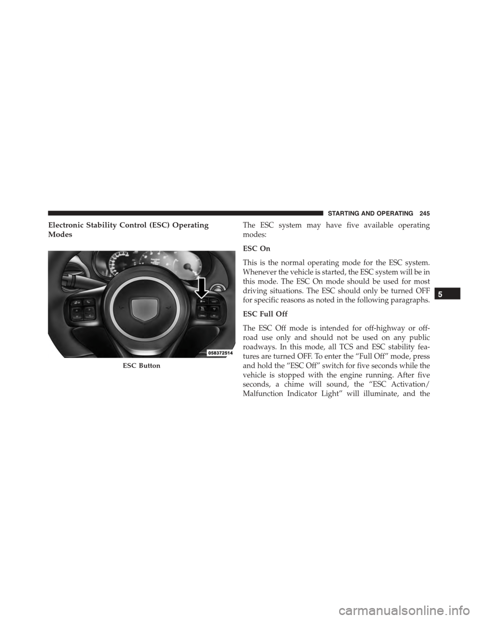
tures are turned OFF. To enter the “Full Off” mode, press
and hold the “ESC Off” switch for five seconds while the
vehicle is stopped with the engine running. After five
seconds, a chime will sound, the “ESC Activation/
Malfunction Indicator Light” will illuminate, and the
ESC Button
5
STARTING AND OPERATING 245
Page 248 of 400
#ESC OFF#message will display in the vehicle cluster (left
of the odometer). The “ESC OFF” message may appear in
the Driver Information Display (DID). Refer to “Driver
Information Display (DID)” in “Understanding Your
Instrument Panel” for further information. To turn ESC
ON again, momentarily press the “ESC Off” switch.
WARNING!
With the ESC switched OFF, the enhanced vehicle
stability offered by ESC is unavailable. In an emer-
gency evasive maneuver, the ESC system will not
engage to assist in maintaining stability. The “Full
Off” ESC mode is intended for off-highway or off-
road only.
Sport Mode — If Equipped
Sport mode has reduced traction control and reduced
stability control. To enter the “Sport Mode” mode, press
the “ESC” switch once (located on the steering wheel).
The “ESC Sport Light” will illuminate, and the#ESC
SPORT#message will display in the vehicle cluster (left of
the odometer). Refer to “Driver Information Display
(DID)” in “Understanding Your Instrument Panel” for
further information.
Track Mode — If Equipped
Track Mode has no traction control and has reduced
stability control. To enter the “Track Mode” mode, press
the “ESC” switch twice. The “ESC Track Light” will
illuminate, and the#ESC TRACK#message will display in
the vehicle cluster (left of the odometer). Refer to “Driver
Information Display (DID)” in “Understanding Your
Instrument Panel” for further information.
Rain Mode
Rain mode offers increased traction control and stability
control for low traction conditions such as wet roads, dry
246 STARTING AND OPERATING
Page 249 of 400
roads during cold temperatures, or when the driver
wants enhanced stability due to lack of familiarity or
experience with the vehicle’s response. To enter the “Rain
Mode” mode, press the “ESC” switch three times. The
“ESC Rain Light” will illuminate, and the#ESC RAIN#
message will display in the vehicle cluster (left of the
odometer). Refer to “Driver Information Display (DID)”
in “Understanding Your Instrument Panel” for further
information.
NOTE:Some models may not offer “Sport” or “Track”
Mode.
TIRE SAFETY INFORMATION
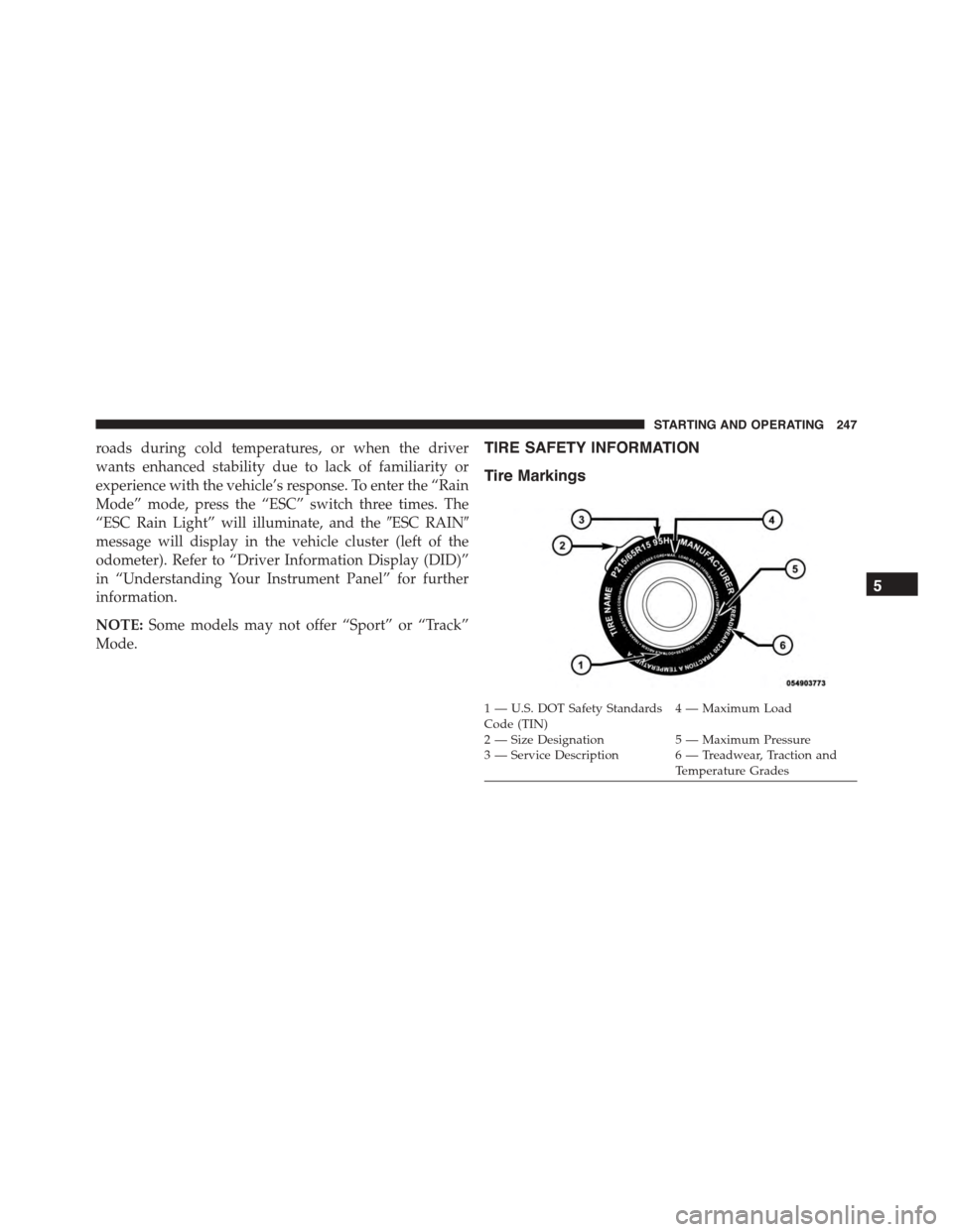
Tire Markings
1—U.S.DOTSafetyStandardsCode (TIN)4—MaximumLoad
2 — Size Designation 5 — Maximum Pressure3 — Service Description 6 — Treadwear, Traction andTemperature Grades
5
STARTING AND OPERATING 247
Page 250 of 400
NOTE:
•P (Passenger) — Metric tire sizing is based on U.S.
design standards. P-Metric tires have the letter “P”
molded into the sidewall preceding the size designa-
tion. Example: P215/65R15 95H.
•European — Metric tire sizing is based on European
design standards. Tires designed to this standard have
the tire size molded into the sidewall beginning with
the section width. The letter#P#is absent from this tire
size designation. Example: 215/65R15 96H.
•LT (Light Truck) — Metric tire sizing is based on U.S.
design standards. The size designation for LT-Metric
tires is the same as for P-Metric tires except for the
letters “LT” that are molded into the sidewall preced-
ing the size designation. Example: LT235/85R16.
•Temporary spare tires are designed for temporary
emergency use only. Temporary high pressure com-
pact spare tires have the letter “T” or “S” molded into
the sidewall preceding the size designation. Example:
T145/80D18 103M.
•High flotation tire sizing is based on U.S. design
standards and it begins with the tire diameter molded
into the sidewall. Example: 31x10.5 R15 LT.
248 STARTING AND OPERATING