engine DODGE VIPER 2015 VX / 3.G Owner's Manual
[x] Cancel search | Manufacturer: DODGE, Model Year: 2015, Model line: VIPER, Model: DODGE VIPER 2015 VX / 3.GPages: 148, PDF Size: 21.7 MB
Page 94 of 148
DID Selectable Menu Items
•TheDIDcanbeusedtoselectandconfigurewhichvehicleinformationisdisplayed.
To s t e p t o e a c h m a i n m e n u f e a t u r e p u s h t h e U Por DOWNbutton once for
each step. A step from the last item in the list will cause the first item in the feature list
to be displayed. The following features are in the Main menu:
•Tach•Audio
•Mph/Kmh•StoredMessages
•VehicleInfo•ScreenSetUp
•FuelEconomy•Performance
•TripA•Hibernate
•TripB
NOTE:
For features in the DID that can be reset (Average Fuel Economy), the DID prompts a
reset with a RIGHT arrow button graphic and the word RESET next to it.
Key Fob Programmable Features
The following features may also be programmed by using the Key Fob transmitter or the
ignition and driver's door lock switch.
NOTE:
Pushing the LOCK button while you are inside the vehicle will activate the Vehicle Security
Alarm. Opening a door with the Vehicle Security Alarm activated will cause the alarm to
sound. Push the UNLOCK button to deactivate the Vehicle Security Alarm.
Unlock On First Press
To u n l o c k e i t h e r t h e d r i v e r ' s s i d e , o r a l l d o o r s , o n t h e f i r s t p u s h o f t h e U N L O C K b u t t o n :
•Push and hold the LOCK button for at least four seconds, but no longer than 10 seconds.
Then, push and hold the UNLOCK button while still holding the LOCK button.
•Releasebothbuttonsatthesametime.
Auto Unlock Doors On Exit
To h a v e a l l o f t h e v e h i c l e d o o r s u n l o c k w h e n a n y d o o r i s o p e n e d :
•Enteryourvehicleandcloseallthedoors,andfastenyourseatbelt.
•CycletheignitionswitchbetweentheLOCKandONpositionfourtimes,endinginthe
LOCK position (do not start the engine).
•PushthepowerdoorUNLOCKswitchtounlockthedoors.Asinglechimewillindicate
that programming is complete.
Sound Horn With Lock
To t u r n t h e h o r n c h i r p o n o r o f f w h e n t h e d o o r s a r e l o c k e d :
•PushtheLOCKbuttonandPANICbuttonatthesametimeforatleastfourseconds,
but no longer than 10 seconds.
•Releasebothbuttonsatthesametime.
ELECTRONICS
92
Page 95 of 148
Flashing Lights With Lock
The turn signal lights flash when the doors are locked, which can be turned on or off.
To t u r n t h i s f e a t u r e o n o r o f f :
•PushandholdtheUNLOCKbuttonandtheLOCKbuttonatthesametimeforatleast
four seconds, but no longer than 10 seconds.
•Releasebothbuttonsatthesametime.
PERFORMANCE PAGES
DID Performance Features
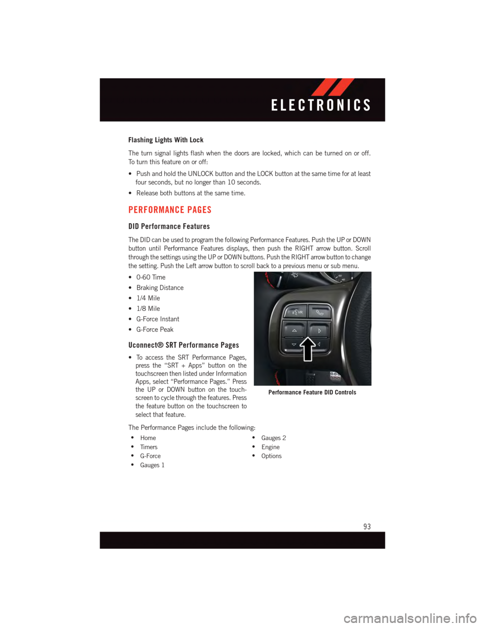
The DID can be used to program the following Performance Features. Push the UP or DOWN
button until Performance Features displays, then push the RIGHT arrow button. Scroll
through the settings using the UP or DOWN buttons. Push the RIGHT arrow button to change
the setting. Push the Left arrow button to scroll back to a previous menu or sub menu.
•0-60Time
•BrakingDistance
•1/4Mile
•1/8Mile
•G-ForceInstant
•G-ForcePeak
Uconnect® SRT Performance Pages
•To a c c e s s t h e S R T P e r f o r m a n c e P a g e s ,
press the “SRT + Apps” button on the
touchscreen then listed under Information
Apps, select “Performance Pages.” Press
the UP or DOWN button on the touch-
screen to cycle through the features. Press
the feature button on the touchscreen to
select that feature.
The Performance Pages include the following:
•Home•Gauges 2
•Ti m e r s•Engine
•G-Force•Options
•Gauges 1
Performance Feature DID Controls
ELECTRONICS
93
Page 96 of 148
PROGRAMMABLE FEATURES
Uconnect® Customer Programmable Features
The Uconnect®system allows you to access Customer Programmable feature settings
such as Display, Voice, Clock, Safety & Driving Assistance, Lights, Doors & Locks, Engine
Off Options, Audio, Phone / Bluetooth, SiriusXM Setup, Restore Settings, Clear Personal
Data, and System Information through buttons on the touchscreen.
•Pressthe“SRT&Apps”buttononthetouchscreen,thenpressthe“Settings”button
on the touchscreen to access the Settings screen. When making a selection, scroll up
or down until the preferred setting is highlighted, then press and release the preferred
setting until a check-mark appears next to the setting, showing that setting has been
selected. The following feature settings are available:
•Display•Audio
•Voice•Phone/Bluetooth
•Clock•SiriusXMSetup
•Safety&DrivingAssistance•RestoreSettings
•Lights•ClearPersonalData
•Doors&Locks•SystemInformation
•EngineOffOptions
UNIVERSAL GARAGE DOOR OPENER (HomeLink®)
HomeLink®replaces up to three hand-held transmitters that operate devices such as
garage door openers, motorized gates, lighting or home security systems. The HomeLink®
unit is powered by your vehicles 12 Volt battery.
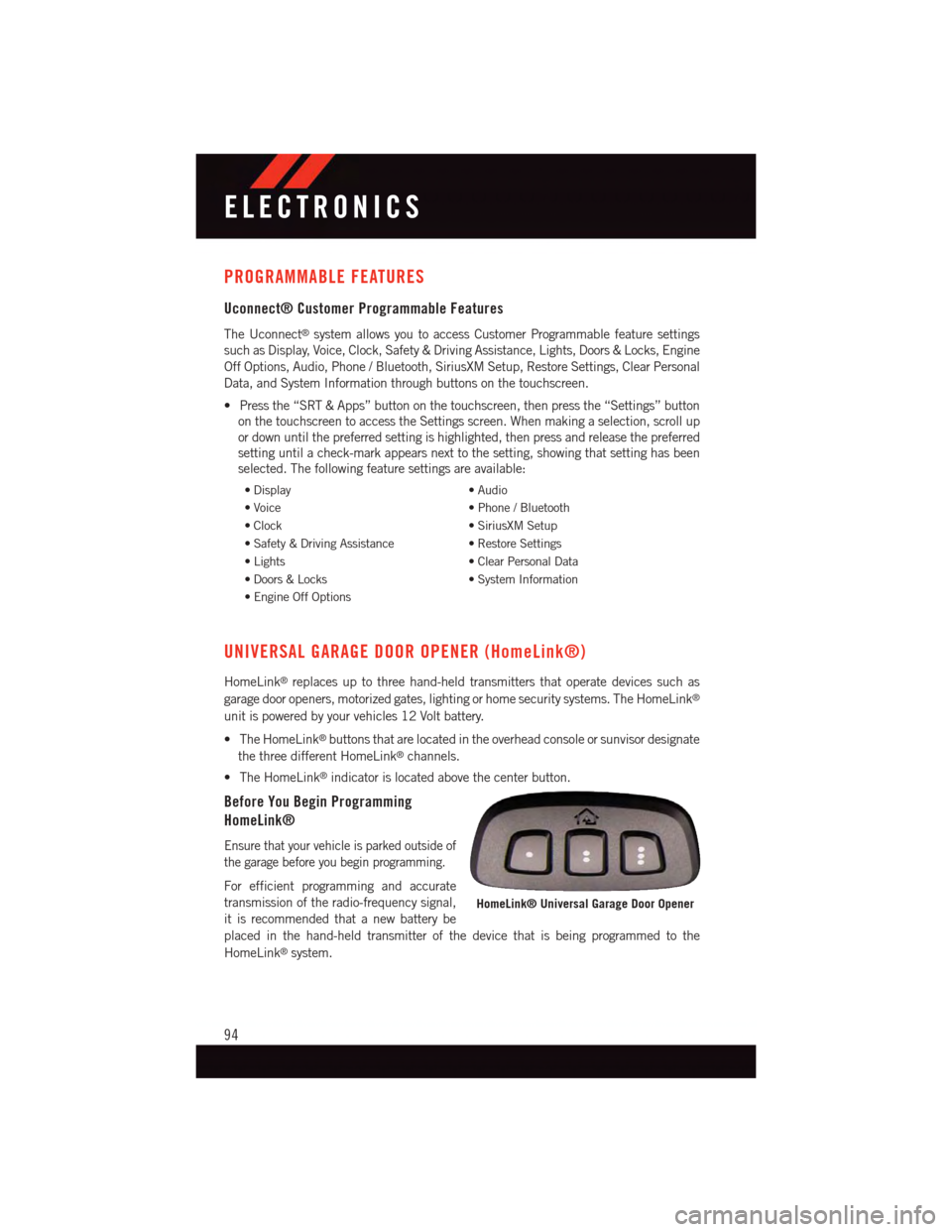
•TheHomeLink®buttons that are located in the overhead console or sunvisor designate
the three different HomeLink®channels.
•TheHomeLink®indicator is located above the center button.
Before You Begin Programming
HomeLink®
Ensure that your vehicle is parked outside of
the garage before you begin programming.
For efficient programming and accurate
transmission of the radio-frequency signal,
it is recommended that a new battery be
placed in the hand-held transmitter of the device that is being programmed to the
HomeLink®system.
HomeLink® Universal Garage Door Opener
ELECTRONICS
94
Page 101 of 148
ROADSIDE ASSISTANCE
Dial toll-free 1-800-521-2779 for U.S. Residents or 1-800-363-4869 for Canadian
Residents.
•Provideyourname,vehicleidentificationnumber,licenseplatenumber,andyour
location, including the telephone number from which you are calling.
•Brieflydescribethenatureoftheproblemandanswerafewsimplequestions.
•Youwillbegiventhenameoftheserviceproviderandanestimatedtimeofarrival.
If you feel you are in an “unsafe situation”, please let us know. With your consent, we
will contact local police or safety authorities.
INSTRUMENT CLUSTER WARNING LIGHTS
–LowFuelWarningLight
This warning light indicates when the fuel level reaches approximately 2.0 gal (7.8 L).
This light will turn on and a single chime will sound.
–ChargingSystemLight
This light shows the status of the electrical charging system. If the charging system light
remains on, it means that the vehicle is experiencing a problem with the charging system.
We recommend you do not continue driving if the charging system light is on. Have the
vehicle serviced immediately.
–OilPressureWarningLight
This light indicates low engine oil pressure. If the light turns on while driving, stop the
vehicle and shut off the engine as soon as possible. A chime will sound when this light
turns on.
We recommend you do not operate the vehicle or engine damage will occur. Have the
vehicle serviced immediately.
–Anti-LockBrake(ABS)Light
This light monitors the Anti-Lock Brake System (ABS).
If the light is not on during starting, stays on or turns on while driving, we recommend you
contact the nearest authorized dealer and have the vehicle serviced immediately.
–AirBagWarningLight
If the light is not on during starting, stays on, or turns on while driving, have the vehicle
serviced by an authorized dealer immediately.
WHAT TO DO IN EMERGENCIES
99
Page 102 of 148
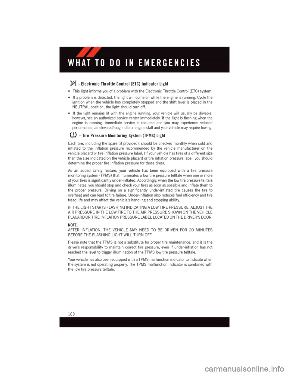
-ElectronicThrottleControl(ETC)IndicatorLight
•ThislightinformsyouofaproblemwiththeElectronicThrottleControl(ETC)system.
•Ifaproblemisdetected,thelightwillcomeonwhiletheengineisrunning.Cyclethe
ignition when the vehicle has completely stopped and the shift lever is placed in the
NEUTRAL position; the light should turn off.
•If the light remains lit with the engine running, your vehicle will usually be drivable;
however, see an authorized service center immediately. If the light is flashing when the
engine is running, immediate service is required and you may experience reduced
performance, an elevated/rough idle or engine stall and your vehicle may require towing.
–TirePressureMonitoringSystem(TPMS)Light
Each tire, including the spare (if provided), should be checked monthly when cold and
inflated to the inflation pressure recommended by the vehicle manufacturer on the
vehicle placard or tire inflation pressure label. (If your vehicle has tires of a different size
than the size indicated on the vehicle placard or tire inflation pressure label, you should
determine the proper tire inflation pressure for those tires).
As an added safety feature, your vehicle has been equipped with a tire pressure
monitoring system (TPMS) that illuminates a low tire pressure telltale when one or more
of your tires is significantly under-inflated. Accordingly, when the low tire pressure telltale
illuminates, you should stop and check your tires as soon as possible and inflate them to
the proper pressure. Driving on a significantly under-inflated tire causes the tire to
overheat and can lead to tire failure. Under-inflation also reduces fuel efficiency and tire
tread life and may affect the vehicle’s handling and stopping ability.
IF THE LIGHT STARTS FLASHING INDICATING A LOW TIRE PRESSURE, ADJUST THE
AIR PRESSURE IN THE LOW TIRE TO THE AIR PRESSURE SHOWN ON THE VEHICLE
PLACARD OR TIRE INFLATION PRESSURE LABEL LOCATED ON THE DRIVER'S DOOR.
NOTE:
AFTER INFLATION, THE VEHICLE MAY NEED TO BE DRIVEN FOR 20 MINUTES
BEFORE THE FLASHING LIGHT WILL TURN OFF.
Please note that the TPMS is not a substitute for proper tire maintenance, and it is the
driver’s responsibility to maintain correct tire pressure, even if under-inflation has not
reached the level to trigger illumination of the TPMS low tire pressure telltale.
Yo u r v e h i c l e h a s a l s o b e e n e q u i p p e d w i t h a T P M S m a l f u n c t i o n i n d i c a t o r t o i n d i c a t e w h e n
the system is not operating properly. The TPMS malfunction indicator is combined with
the low tire pressure telltale.
WHAT TO DO IN EMERGENCIES
100
Page 103 of 148
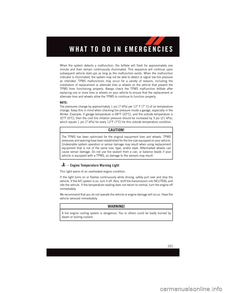
When the system detects a malfunction, the telltale will flash for approximately one
minute and then remain continuously illuminated. This sequence will continue upon
subsequent vehicle start-ups as long as the malfunction exists. When the malfunction
indicator is illuminated, the system may not be able to detect or signal low tire pressure
as intended. TPMS malfunctions may occur for a variety of reasons, including the
installation of replacement or alternate tires or wheels on the vehicle that prevent the
TPMS from functioning properly. Always check the TPMS malfunction telltale after
replacing one or more tires or wheels on your vehicle to ensure that the replacement or
alternate tires and wheels allow the TPMS to continue to function properly.
NOTE:
Ti r e p r e s s u r e s c h a n g e b y a p p r o x i m a t e l y 1 p s i ( 7 k P a ) p e r 1 2 ° F ( 7 ° C ) o f a i r t e m p e r a t u r e
change. Keep this in mind when checking tire pressure inside a garage, especially in the
Winter. Example: If garage temperature is 68°F (20°C), and the outside temperature is
32°F (0°C), then the cold tire inflation pressure should be increased by 3 psi (21 kPa),
which equals 1 psi (7 kPa) for every 12°F (7°C) for this outside temperature condition.
CAUTION!
The TPMS has been optimized for the original equipment tires and wheels. TPMS
pressures and warning have been established for the tire size equipped on your vehicle.
Undesirable system operation or sensor damage may result when using replacement
equipment that is not of the same size, type, and/or style. Aftermarket wheels can
cause sensor damage. Do not use tire sealant from a can, or balance beads if your
vehicle is equipped with a TPMS, as damage to the sensors may result.
–EngineTemperatureWarningLight
This light warns of an overheated engine condition.
If the light turns on or flashes continuously while driving, safely pull over and stop the
vehicle. If the A/C system is on, turn it off. Also, shift the transmission into NEUTRAL and
idle the vehicle. If the temperature reading does not return to normal, turn the engine off
immediately.
We recommend that you do not operate the vehicle or engine damage will occur. Have the
vehicle serviced immediately.
WARNING!
Ahotenginecoolingsystemisdangerous.Youorotherscouldbebadlyburnedby
steam or boiling coolant.
WHAT TO DO IN EMERGENCIES
101
Page 105 of 148
WARNING!
Driving a vehicle with the red brake light on is dangerous. Part of the brake system may
have failed. It will take longer to stop the vehicle. You could have a collision. Have the
vehicle checked immediately.
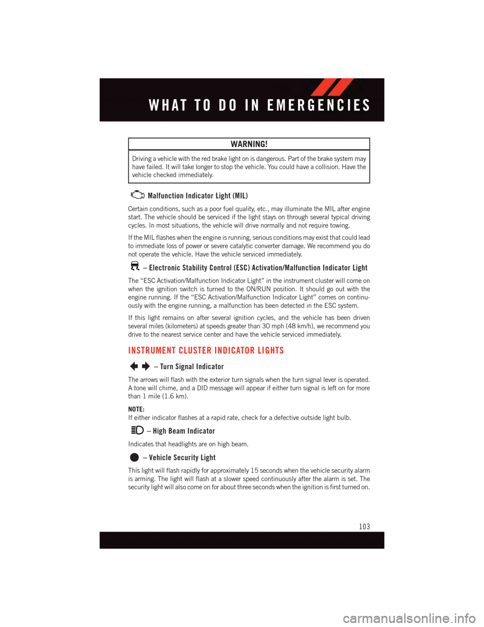
Malfunction Indicator Light (MIL)
Certain conditions, such as a poor fuel quality, etc., may illuminate the MIL after engine
start. The vehicle should be serviced if the light stays on through several typical driving
cycles. In most situations, the vehicle will drive normally and not require towing.
If the MIL flashes when the engine is running, serious conditions may exist that could lead
to immediate loss of power or severe catalytic converter damage. We recommend you do
not operate the vehicle. Have the vehicle serviced immediately.
–ElectronicStabilityControl(ESC)Activation/MalfunctionIndicatorLight
The “ESC Activation/Malfunction Indicator Light” in the instrument cluster will come on
when the ignition switch is turned to the ON/RUN position. It should go out with the
engine running. If the “ESC Activation/Malfunction Indicator Light” comes on continu-
ously with the engine running, a malfunction has been detected in the ESC system.
If this light remains on after several ignition cycles, and the vehicle has been driven
several miles (kilometers) at speeds greater than 30 mph (48 km/h), we recommend you
drive to the nearest service center and have the vehicle serviced immediately.
INSTRUMENT CLUSTER INDICATOR LIGHTS
–TurnSignalIndicator
The arrows will flash with the exterior turn signals when the turn signal lever is operated.
Atonewillchime,andaDIDmessagewillappearifeitherturnsignalisleftonformore
than 1 mile (1.6 km).
NOTE:
If either indicator flashes at a rapid rate, check for a defective outside light bulb.
–HighBeamIndicator
Indicates that headlights are on high beam.
–VehicleSecurityLight
This light will flash rapidly for approximately 15 seconds when the vehicle security alarm
is arming. The light will flash at a slower speed continuously after the alarm is set. The
security light will also come on for about three seconds when the ignition is first turned on.
WHAT TO DO IN EMERGENCIES
103
Page 106 of 148
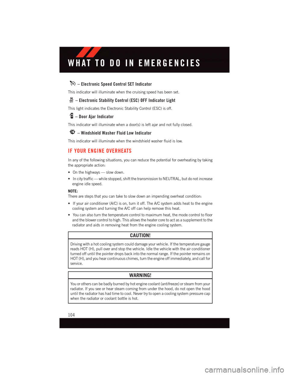
–ElectronicSpeedControlSETIndicator
This indicator will illuminate when the cruising speed has been set.
–ElectronicStabilityControl(ESC)OFFIndicatorLight
This light indicates the Electronic Stability Control (ESC) is off.
–DoorAjarIndicator
This indicator will illuminate when a door(s) is left ajar and not fully closed.
–WindshieldWasherFluidLowIndicator
This indicator will illuminate when the windshield washer fluid is low.
IF YOUR ENGINE OVERHEATS
In any of the following situations, you can reduce the potential for overheating by taking
the appropriate action:
•Onthehighways—slowdown.
•Incitytraffic—whilestopped,shiftthetransmissiontoNEUTRAL,butdonotincrease
engine idle speed.
NOTE:
There are steps that you can take to slow down an impending overheat condition:
•Ifyourairconditioner(A/C)ison,turnitoff.TheA/Csystemaddsheattotheengine
cooling system and turning the A/C off can help remove this heat.
•Youcanalsoturnthetemperaturecontroltomaximumheat,themodecontroltofloor
and the blower control to high. This allows the heater core to act as a supplement to the
radiator and aids in removing heat from the engine cooling system.
CAUTION!
Driving with a hot cooling system could damage your vehicle. If the temperature gauge
reads HOT (H), pull over and stop the vehicle. Idle the vehicle with the air conditioner
turned off until the pointer drops back into the normal range. If the pointer remains on
HOT (H), and you hear continuous chimes, turn the engine off immediately, and call for
service.
WARNING!
Yo u o r o t h e r s c a n b e b a d l y b u r n e d b y h o t e n g i n e c o o l a n t ( a n t i f r e e z e ) o r s t e a m f r o m y o u r
radiator. If you see or hear steam coming from under the hood, do not open the hood
until the radiator has had time to cool. Never try to open a cooling system pressure cap
when the radiator or coolant bottle is hot.
WHAT TO DO IN EMERGENCIES
104
Page 109 of 148
4. Remove the cap from the valve stem and then screw the fitting at the end of the
Sealant Hose (6) onto the valve stem.
5. Uncoil the Power Plug (8) and insert the plug into the vehicle’s 12 Volt power outlet.
6. Do not remove foreign objects (e.g., screws or nails) from the tire.
(C) Injecting Tire Service Kit Sealant Into The Deflated Tire:
Always start the engine before turning ON the Tire Service Kit.
NOTE:
Manual transmission vehicles must have the parking brake engaged and the shift lever in
NEUTRAL.
After pushing the Power Button (4), the sealant (white fluid) will flow from the Sealant
Bottle (1) through the Sealant Hose (6) and into the tire.
NOTE:
Sealant may leak out through the puncture in the tire.
If the sealant (white fluid) does not flow within0–10seconds through the Sealant Hose (6):
1. Push the Power Button (4) to turn Off the Tire Service Kit. Disconnect the Sealant Hose
(6) from the valve stem. Make sure the valve stem is free of debris. Reconnect the
Sealant Hose (6) to the valve stem. Check that the Mode Select Knob (5) is in the
Sealant Mode position and not Air Mode. Push the Power Button (4) to turn On the Tire
Service Kit.
2. Connect the Power Plug (8) to a different 12 Volt power outlet in your vehicle or
another vehicle, if available. Make sure the engine is running before turning ON the
Ti r e S e r v i c e K i t .
3. The Sealant Bottle (1) may be empty due to previous use. Call for assistance.
NOTE:
If the Mode Select Knob (5) is on Air Mode and the pump is operating, air will dispense
from the Air Pump Hose (7) only, not the Sealant Hose (6).
If the sealant (white fluid) does flow through the Sealant Hose (6):
1. Continue to operate the pump until sealant is no longer flowing through the hose
(typically takes 30 - 70 seconds). As the sealant flows through the Sealant Hose (6),
the Pressure Gauge (3) can read as high as 70 psi (4.8 Bar). The Pressure Gauge (3)
will decrease quickly from approximately 70 psi (4.8 Bar) to the actual tire pressure
when the Sealant Bottle (1) is empty.
2. The pump will start to inject air into the tire immediately after the Sealant Bottle (1)
is empty. Continue to operate the pump and inflate the tire to the pressure indicated
on the tire pressure label on the driver-side latch pillar (recommended pressure).
Check the tire pressure by looking at the Pressure Gauge (3).
WHAT TO DO IN EMERGENCIES
107
Page 113 of 148
JUMP-STARTING
•If your vehicle has a discharged battery it
can be jump-started using a set of jumper
cables and a battery in another vehicle or
by using a portable battery booster pack.
•Jump-startingcanbedangerousifdone
improperly so please follow the proce-
dures in this section carefully.
NOTE:
When using a portable battery booster pack
follow the manufacturer’s operating instruc-
tions and precautions.
Preparations for Jump-Start
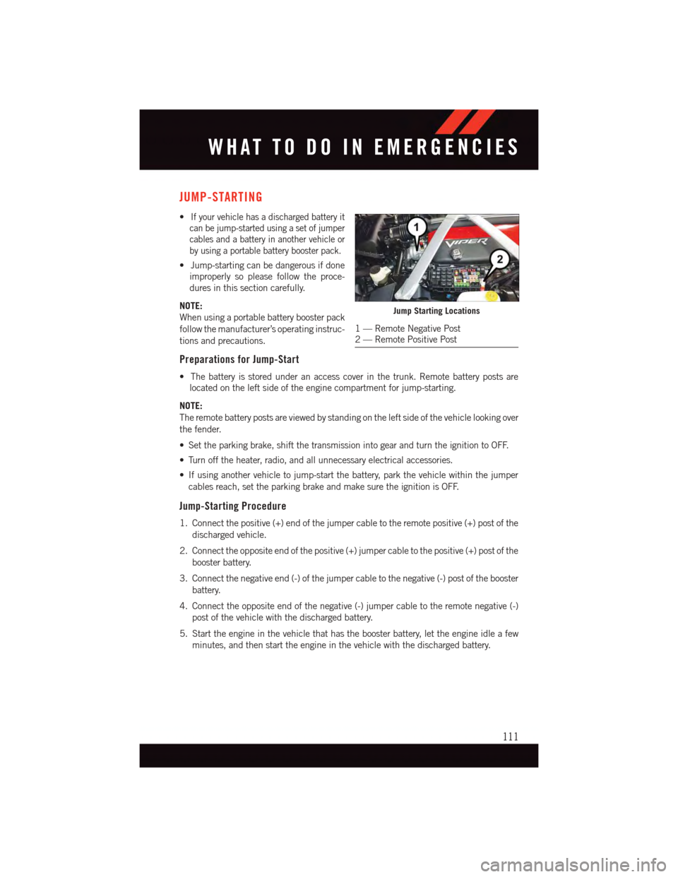
•Thebatteryisstoredunderanaccesscoverinthetrunk.Remotebatterypostsare
located on the left side of the engine compartment for jump-starting.
NOTE:
The remote battery posts are viewed by standing on the left side of the vehicle looking over
the fender.
•Settheparkingbrake,shiftthetransmissionintogearandturntheignitiontoOFF.
•Turnofftheheater,radio,andallunnecessaryelectricalaccessories.
•Ifusinganothervehicletojump-startthebattery,parkthevehiclewithinthejumper
cables reach, set the parking brake and make sure the ignition is OFF.
Jump-Starting Procedure
1. Connect the positive (+) end of the jumper cable to the remote positive (+) post of the
discharged vehicle.
2. Connect the opposite end of the positive (+) jumper cable to the positive (+) post of the
booster battery.
3. Connect the negative end (-) of the jumper cable to the negative (-) post of the booster
battery.
4. Connect the opposite end of the negative (-) jumper cable to the remote negative (-)
post of the vehicle with the discharged battery.
5. Start the engine in the vehicle that has the booster battery, let the engine idle a few
minutes, and then start the engine in the vehicle with the discharged battery.
Jump Starting Locations
1—RemoteNegativePost2—RemotePositivePost
WHAT TO DO IN EMERGENCIES
111