lock DODGE VIPER 2015 VX / 3.G Owner's Manual
[x] Cancel search | Manufacturer: DODGE, Model Year: 2015, Model line: VIPER, Model: DODGE VIPER 2015 VX / 3.GPages: 148, PDF Size: 21.7 MB
Page 96 of 148
PROGRAMMABLE FEATURES
Uconnect® Customer Programmable Features
The Uconnect®system allows you to access Customer Programmable feature settings
such as Display, Voice, Clock, Safety & Driving Assistance, Lights, Doors & Locks, Engine
Off Options, Audio, Phone / Bluetooth, SiriusXM Setup, Restore Settings, Clear Personal
Data, and System Information through buttons on the touchscreen.
•Pressthe“SRT&Apps”buttononthetouchscreen,thenpressthe“Settings”button
on the touchscreen to access the Settings screen. When making a selection, scroll up
or down until the preferred setting is highlighted, then press and release the preferred
setting until a check-mark appears next to the setting, showing that setting has been
selected. The following feature settings are available:
•Display•Audio
•Voice•Phone/Bluetooth
•Clock•SiriusXMSetup
•Safety&DrivingAssistance•RestoreSettings
•Lights•ClearPersonalData
•Doors&Locks•SystemInformation
•EngineOffOptions
UNIVERSAL GARAGE DOOR OPENER (HomeLink®)
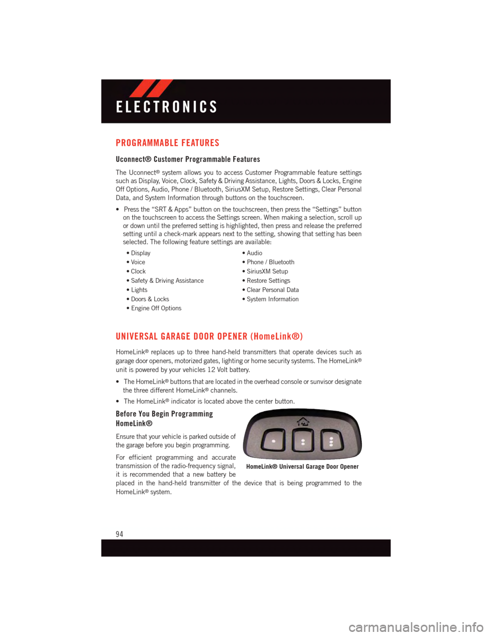
HomeLink®replaces up to three hand-held transmitters that operate devices such as
garage door openers, motorized gates, lighting or home security systems. The HomeLink®
unit is powered by your vehicles 12 Volt battery.
•TheHomeLink®buttons that are located in the overhead console or sunvisor designate
the three different HomeLink®channels.
•TheHomeLink®indicator is located above the center button.
Before You Begin Programming
HomeLink®
Ensure that your vehicle is parked outside of
the garage before you begin programming.
For efficient programming and accurate
transmission of the radio-frequency signal,
it is recommended that a new battery be
placed in the hand-held transmitter of the device that is being programmed to the
HomeLink®system.
HomeLink® Universal Garage Door Opener
ELECTRONICS
94
Page 98 of 148
Programming A Non-Rolling Code
NOTE:
For programming Garage Door Openers manufactured before 1995.
1. Turn the ignition switch to the ON/RUN position.
2. Place the hand-held transmitter 1 to 3 inches (3 to 8 cm) away from the HomeLink®
button you wish to program while keeping the HomeLink®indicator light in view.
3. Push and hold the HomeLink®button you want to program while you push and hold
the hand-held transmitter button.
4. Continue to hold both buttons and observe the indicator light. The HomeLink®
indicator will flash slowly and then rapidly after HomeLink®has received the fre-
quency signal from the hand-held transmitter. Release both buttons after the indicator
light changes from slow to rapid.
5. Push and hold the programmed HomeLink®button and observe the indicator light.
If the indicator light stays on constantly, programming is complete and the garage door
(or device) should activate when the HomeLink®button is pushed.
6. To program the two remaining HomeLink®buttons, repeat each step for each
remaining button. DO NOT erase the channels.
Using HomeLink®
To o p e r a t e , p u s h a n d r e l e a s e t h e p r o g r a m m e d H o m e L i n k®button. Activation will now
occur for the programmed device (i.e., garage door opener, gate operator, security system,
entry door lock, home/office lighting, etc.,). The hand-held transmitter of the device may
also be used at any time.
WARNING!
•Yourmotorizeddoororgatewillopenandclosewhileyouareprogrammingthe
universal transceiver. Do not program the transceiver if people or pets are in the
path of the door or gate.
•Donotrunyourvehicleinaclosedgarageorconfinedareawhileprogrammingthe
transceiver. Exhaust gas from your vehicle contains Carbon Monoxide (CO) which is
odorless and colorless. Carbon Monoxide is poisonous when inhaled and can cause
you and others to be severely injured or killed.
ELECTRONICS
96
Page 101 of 148
ROADSIDE ASSISTANCE
Dial toll-free 1-800-521-2779 for U.S. Residents or 1-800-363-4869 for Canadian
Residents.
•Provideyourname,vehicleidentificationnumber,licenseplatenumber,andyour
location, including the telephone number from which you are calling.
•Brieflydescribethenatureoftheproblemandanswerafewsimplequestions.
•Youwillbegiventhenameoftheserviceproviderandanestimatedtimeofarrival.
If you feel you are in an “unsafe situation”, please let us know. With your consent, we
will contact local police or safety authorities.
INSTRUMENT CLUSTER WARNING LIGHTS
–LowFuelWarningLight
This warning light indicates when the fuel level reaches approximately 2.0 gal (7.8 L).
This light will turn on and a single chime will sound.
–ChargingSystemLight
This light shows the status of the electrical charging system. If the charging system light
remains on, it means that the vehicle is experiencing a problem with the charging system.
We recommend you do not continue driving if the charging system light is on. Have the
vehicle serviced immediately.
–OilPressureWarningLight
This light indicates low engine oil pressure. If the light turns on while driving, stop the
vehicle and shut off the engine as soon as possible. A chime will sound when this light
turns on.
We recommend you do not operate the vehicle or engine damage will occur. Have the
vehicle serviced immediately.
–Anti-LockBrake(ABS)Light
This light monitors the Anti-Lock Brake System (ABS).
If the light is not on during starting, stays on or turns on while driving, we recommend you
contact the nearest authorized dealer and have the vehicle serviced immediately.
–AirBagWarningLight
If the light is not on during starting, stays on, or turns on while driving, have the vehicle
serviced by an authorized dealer immediately.
WHAT TO DO IN EMERGENCIES
99
Page 104 of 148
–SeatBeltReminderLight
When the ignition switch is first turned to the ON/RUN position, this light will turn on for
four to eight seconds as a bulb check. During the bulb check, if the driver's seat belt is
unbuckled, a chime will sound. After the bulb check or when driving, if the driver or front
passenger seat belt remains unbuckled, the Seat Belt Indicator Light will flash or remain
on continuously. Refer to “Seat Belt Systems” in “Things To Know Before Starting” in your
Owner’s Manual on the DVD for further information.
–BrakeWarningLight
This light monitors various brake functions, including brake fluid level and parking brake
application. If the brake light turns on, it may indicate that the parking brake is applied,
that the brake fluid level is low, or that there is a problem with the anti-lock brake system
reservoir.
If the light remains on when the parking brake has been disengaged, and the fluid level is
at the full mark on the master cylinder reservoir, it indicates a possible brake hydraulic
system malfunction or that a problem with the Brake Booster has been detected by the
Anti-Lock Brake System (ABS)/Electronic Stability Control (ESC) system. In this case, the
light will remain on until the condition has been corrected. If the problem is related to the
brake booster, the ABS pump will run when applying the brake, and a brake pedal
pulsation may be felt during each stop.
The dual brake system provides a reserve braking capacity in the event of a failure to a portion
of the hydraulic system. A leak in either half of the dual brake system is indicated by the
Brake Warning Light, which will turn on when the brake fluid level in the master cylinder has
dropped below a specified level. The light will remain on until the cause is corrected.
Vehicles equipped with the Anti-Lock Brake System (ABS) are also equipped with Electronic
Brake Force Distribution (EBD). In the event of an EBD failure, the Brake Warning Light will
turn on along with the ABS Light. Immediate repair to the ABS system is required.
Operation of the Brake Warning Light can be checked by turning the ignition switch from the
OFF position to the ON/RUN position. The light should illuminate for approximately two
seconds. The light should then turn off unless the parking brake is applied or a brake fault is
detected. If the light does not illuminate, have the light inspected by an authorized dealer.
The light also will turn on when the parking brake is applied with the ignition switch in the
ON/RUN position.
NOTE:
This light shows only that the parking brake is applied. It does not show the degree of
brake application.
WHAT TO DO IN EMERGENCIES
102
Page 111 of 148
4. Have the tire inspected and repaired or replaced at the earliest opportunity at an
authorized dealer or tire service center.
5. Remove the Speed Limit sticker from the instrument panel after the tire has been
repaired.
6. Replace the Sealant Bottle (1) and Sealant Hose (6) assembly at your authorized
dealer as soon as possible. Refer to “(F) Sealant Bottle and Hose Replacement.”
NOTE:
•Ifthetirebecomesover-inflated,pushtheDeflationButtontoreducethetirepressure
to the recommended inflation pressure before continuing.
•Whenhavingthetireserviced,advisetheauthorizeddealerorservicecenterthatthe
tire has been sealed using the Tire Service Kit.
(F) Sealant Bottle And Hose Replacement:
1. Uncoil the Sealant Hose (6) (clear in color).
2. Locate the round Sealant Bottle release button in the recessed area under the sealant
bottle.
3. Push the Sealant Bottle release button. The Sealant Bottle (1) will pop up. Remove the
bottle and dispose of it accordingly.
4. Clean any remaining sealant from the Tire Service Kit housing.
5. Position the new Sealant Bottle (1) in the housing so that the Sealant Hose (6) aligns
with the hose slot in the front of the housing. Push the bottle into the housing. An
audible click will be heard indicating the bottle is locked into place.
6. Verify that the cap is installed on the fitting at the end of the Sealant Hose (6) and
return the hose to its storage area (located on the bottom of the air pump).
7. Return the Tire Service Kit to its storage location in the vehicle.
NOTE:
•ThemetalendfittingfromPowerPlug(8)maygethotafteruse,soitshouldbehandled
carefully.
•FailuretoreinstallthecaponthefittingattheendoftheSealantHose(6)canresult
in sealant contacting your skin, clothing, and the vehicle’s interior. It can also result in
sealant contacting internal Tire Service Kit components which may cause permanent
damage to the kit.
WHAT TO DO IN EMERGENCIES
109
Page 117 of 148
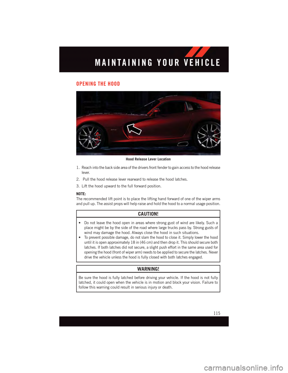
OPENING THE HOOD
1.Reach into the back side area of the drivers front fender to gain access to the hood release
lever.
2. Pull the hood release lever rearward to release the hood latches.
3. Lift the hood upward to the full forward position.
NOTE:
The recommended lift point is to place the lifting hand forward of one of the wiper arms
and pull up. The assist props will help raise and hold the hood to a normal usage position.
CAUTION!
•Donotleavethehoodopeninareaswherestronggustofwindarelikely.Sucha
place might be by the side of the road where large trucks pass by. Strong gusts of
wind may damage the hood. Always close the hood in such situations.
•To p r e v e n t p o s s i b l e d a m a g e , d o n o t s l a m t h e h o o d t o c l o s e i t . S i m p l y l o w e r t h e h o o d
until it is open approximately 18 in (46 cm) and then drop it. This should secure both
latches. If both latches did not secure, a slight push effort in the same area used for
opening the hood (front of wiper arm) needs to be applied to secure the latches. Never
drive the vehicle unless the hood is fully closed with both latches engaged.
WARNING!
Be sure the hood is fully latched before driving your vehicle. If the hood is not fully
latched, it could open when the vehicle is in motion and block your vision. Failure to
follow this warning could result in serious injury or death.
Hood Release Lever Location
MAINTAINING YOUR VEHICLE
115
Page 126 of 148
FUSES
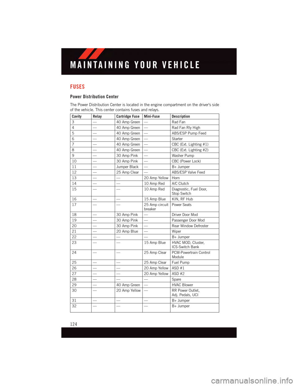
Power Distribution Center
The Power Distribution Center is located in the engine compartment on the driver's side
of the vehicle. This center contains fuses and relays.
Cavity Relay Cartridge Fuse Mini-Fuse Description
3—40 Amp Green —Rad Fan
4—40 Amp Green —Rad Fan Rly High
5—40 Amp Green —ABS/ESP Pump Feed
6—40 Amp Green —Starter
7—40 Amp Green —CBC (Ext. Lighting #1)
8—40 Amp Green —CBC (Ext. Lighting #2)
9—30 Amp Pink —Washer Pump
10 —30 Amp Pink —CBC (Power Lock)
11 —Jumper Black —B+ Jumper
12 —25 Amp Clear —ABS/ESP Valve Feed
13 ——20 Amp Yellow Horn
14 ——10 Amp Red A/C Clutch
15 ——10 Amp Red Diagnostic, Fuel Door,Stop Switch
16 ——15 Amp Blue KIN, RF Hub
17 ——25 Amp circuitbreakerPower Seats
18 —30 Amp Pink —Driver Door Mod
19 —30 Amp Pink —Passenger Door Mod
20 —30 Amp Pink —Rear Window Defroster
21 —20 Amp Blue —Wiper
22 ———B+ Jumper
23 ——15 Amp Blue HVAC MOD, Cluster,ICS-Switch Bank
24 ——25 Amp Clear PCM-Powertrain ControlModule
25 ——25 Amp Clear Fuel Pump
26 ——20 Amp Yellow ASD #1
27 ——20 Amp Yellow ASD #2
28 ———Spare
29 —40 Amp Green —HVAC Blower
30 —20 Amp Yellow —RR Power Outlet,Adj. Pedals, UCI
31 ———B+ Jumper
32 ———B+ Jumper
MAINTAINING YOUR VEHICLE
124
Page 134 of 148
AUTHENTIC ACCESSORIES BY MOPAR®
•ThefollowinghighlightsjustsomeofthemanyAuthenticViperAccessoriesbyMopar®
featuring a fit, finish, and functionality specifically for your Viper.
•InchoosingAuthenticAccessoriesyougainfarmorethanexpressivestyle,premium
protection, or extreme entertainment, you also benefit from enhancing your vehicle
with accessories that have been thoroughly tested and factory-approved.
•ForthefulllineofAuthenticViperAccessoriesbyMopar®,visityourlocaldealershipor
online at mopar.com for U.S. residents and mopar.ca for Canadian residents.
NOTE:
All parts are subject to availability.
PERFORMANCE:
•BrakeRotors•CarbonFiberX-Brace
EXTERIOR:
•CustomWheels•WheelLocks
•VehicleDustCovers
INTERIOR:
•PremiumCarpetFloorMats•PremiumCarpetCargoMat
•DoorSillGuards•ShiftKnobs
•PedalKits•UniqueKatzkinLeatherInteriors
•CargoSecurityCover
ELECTRONICS:
•HarmanKardon®Speaker Upgrade • Wireless Charging Pad
•BatteryCharger•ElectronicVehicleTrackingSystem
MOPAR® ACCESSORIES
132
Page 135 of 148
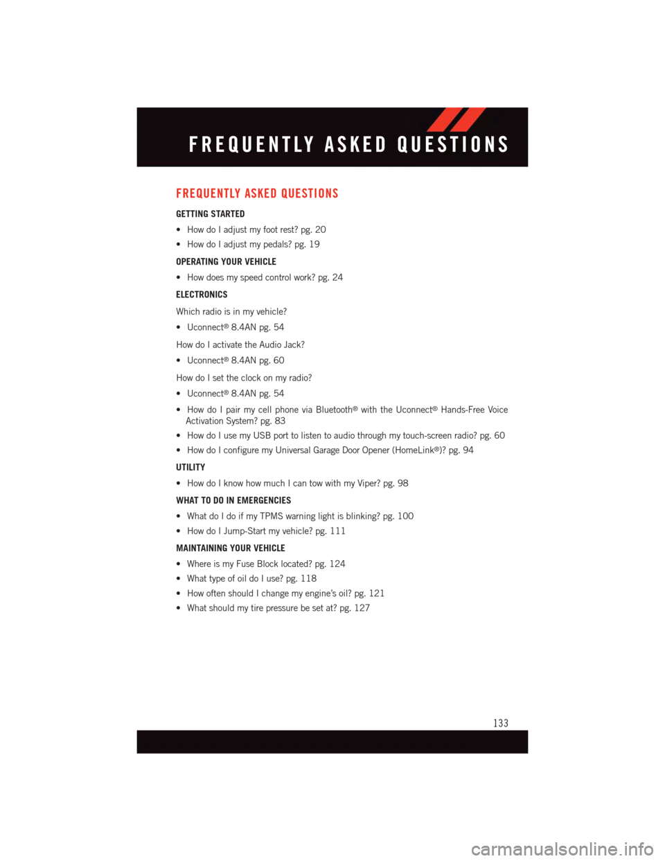
FREQUENTLY ASKED QUESTIONS
GETTING STARTED
•HowdoIadjustmyfootrest?pg.20
•HowdoIadjustmypedals?pg.19
OPERATING YOUR VEHICLE
•Howdoesmyspeedcontrolwork?pg.24
ELECTRONICS
Which radio is in my vehicle?
•Uconnect®8.4AN pg. 54
How do I activate the Audio Jack?
•Uconnect®8.4AN pg. 60
How do I set the clock on my radio?
•Uconnect®8.4AN pg. 54
•HowdoIpairmycellphoneviaBluetooth®with the Uconnect®Hands-Free Voice
Activation System? pg. 83
•HowdoIusemyUSBporttolistentoaudiothroughmytouch-screenradio?pg.60
•HowdoIconfiguremyUniversalGarageDoorOpener(HomeLink®)? pg. 94
UTILITY
•HowdoIknowhowmuchIcantowwithmyViper?pg.98
WHAT TO DO IN EMERGENCIES
•WhatdoIdoifmyTPMSwarninglightisblinking?pg.100
•HowdoIJump-Startmyvehicle?pg.111
MAINTAINING YOUR VEHICLE
•WhereismyFuseBlocklocated?pg.124
•WhattypeofoildoIuse?pg.118
•HowoftenshouldIchangemyengine’soil?pg.121
•Whatshouldmytirepressurebesetat?pg.127
FREQUENTLY ASKED QUESTIONS
133
Page 136 of 148
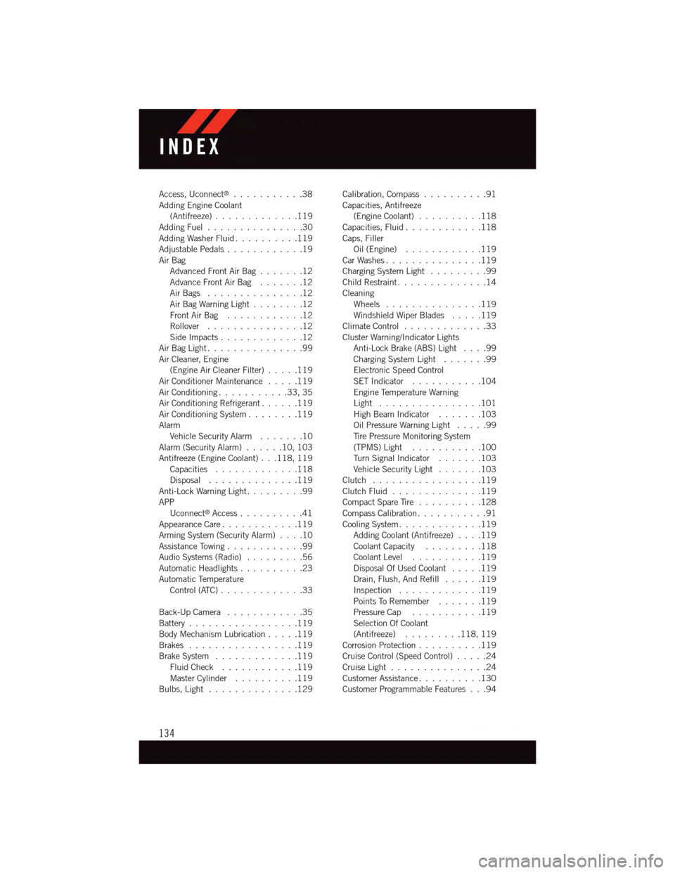
Access, Uconnect®...........38Adding Engine Coolant(Antifreeze).............119Adding Fuel...............30Adding Washer Fluid..........119Adjustable Pedals............19Air BagAdvanced Front Air Bag.......12Advance Front Air Bag.......12Air Bags . . . . . . . . . . . . . . .12Air Bag Warning Light . . . . . . . .12Front Air Bag . . . . . . . . . . . .12Rollover . . . . . . . . . . . . . . .12Side Impacts.............12Air Bag Light . . . . . . . . . . . . . . .99Air Cleaner, Engine(Engine Air Cleaner Filter).....119Air Conditioner Maintenance.....119Air Conditioning...........33,35Air Conditioning Refrigerant......119Air Conditioning System........119AlarmVehicle Security Alarm.......10Alarm (Security Alarm)......10,103Antifreeze (Engine Coolant) . . .118, 119Capacities.............118Disposal . . . . . . . . . . . . . .119Anti-Lock Warning Light.........99APPUconnect®Access..........41Appearance Care............119Arming System (Security Alarm)....10Assistance Towing............99Audio Systems (Radio).........56Automatic Headlights..........23Automatic TemperatureControl (ATC) . . . . . . . . . . . . .33
Back-Up Camera............35Battery.................119Body Mechanism Lubrication.....119Brakes . . . . . . . . . . . . . . . . .119Brake System.............119Fluid Check............119Master Cylinder..........119Bulbs, Light . . . . . . . . . . . . . .129
Calibration, Compass..........91Capacities, Antifreeze(Engine Coolant)..........118Capacities, Fluid............118Caps, FillerOil (Engine)............119Car Washes . . . . . . . . . . . . . . .119Charging System Light.........99Child Restraint..............14CleaningWheels...............119Windshield Wiper Blades.....119Climate Control . . . . . . . . . . . . .33Cluster Warning/Indicator LightsAnti-Lock Brake (ABS) Light....99Charging System Light.......99Electronic Speed ControlSET Indicator . . . . . . . . . . .104Engine Temperature WarningLight . . . . . . . . . . . . . . . .101High Beam Indicator.......103Oil Pressure Warning Light . . . . .99Ti r e P r e s s u r e M o n i t o r i n g S y s t e m(TPMS) Light...........100Tu r n S i g n a l I n d i c a t o r.......103Vehicle Security Light.......103Clutch . . . . . . . . . . . . . . . . .119Clutch Fluid . . . . . . . . . . . . . .119Compact Spare Tire..........128Compass Calibration...........91Cooling System . . . . . . . . . . . . .119Adding Coolant (Antifreeze)....119Coolant Capacity.........118Coolant Level...........119Disposal Of Used Coolant.....119Drain, Flush, And Refill......119Inspection . . . . . . . . . . . . .119Points To Remember.......119Pressure Cap . . . . . . . . . . .119Selection Of Coolant(Antifreeze).........118, 119Corrosion Protection . . . . . . . . . .119Cruise Control (Speed Control).....24Cruise Light . . . . . . . . . . . . . . .24Customer Assistance..........130Customer Programmable Features . . .94
INDEX
134