ECO mode FIAT 127 1979 2.G Workshop Manual
[x] Cancel search | Manufacturer: FIAT, Model Year: 1979, Model line: 127, Model: FIAT 127 1979 2.GPages: 34, PDF Size: 6.87 MB
Page 8 of 34

Fiat 127 Internet Fan Club (http://fiat127.okruhy.cz) Fiat 127 - 1050
8/34
Air correction jet 0.0728 in (1.85 mm)
Slow running jet 0.0177 in (0.45 mm)
Emulsion tube type F74
Accelerator pump jet 0.0157 in (0.40 mm)
Needle valve seat 0.0591 in (1.50 mm)
Accelerator pump output (10 strokes) 2 to 3 cm
3
Cold starting device Automatic choke
Float level 1.4016 to 1.4213 in (35.6 to 36. 1 mm)
CO level 2.5%
Solex C32 TDI/4 carburettor (C, L and CL models)
Venturi diameter 0.8465 in (21.5 mm)
Main jet 0.0453 in (1.15 mm)
Air correction jet 0.0768 in (1.95 mm)
Slow running jet 0.0177 in (0.45 mm)
Emulsion tube type 71
Accelerator pump jet 0.0177 in (0.45 mm)
Needle valve seat 0.0630 in (1.60 mm)
Accelerator pump output I10 strokes) 3 to 5 cm
3
Cold starting device Automatic choke
Float level 0.8661 to 0.9449 in (22.0 to 24. 0 mm)
CO level 2.5%
Weber 34 DMTR 47/250 carburettor (Sport models) Primary venturi Secondary venturi
Venturi diameter 0.8661 in (22.0 mm) 0.9449 in (24.0 mm)
Main jet 0.0421 in (1.07 mm) 0.0500 in (1. 27 mm)
Air correction jet 0.0728 in (1.85 mm) 0.086 6 in (2.20 mm)
Slow running jet 0.0177 in (0.45 mm) 0.0276 in (0. 70 mm)
Slow running air bleed 0.0413 in (1.05 mm) 0.027 6 in (0.70 mm)
Accelerator pump jet 0.0157 in (0.40 mm) ---
Needle valve seat 0.0689 in (1.75 mm)
Accelerator pump output (10 strokes) 8.55 cm
3
Cold starting device Manually operated strangler ch oke
Float level 0.2657 to 0.2854 in (6.75 to 7.25 mm)
Fuel pump
Output 75 litres/hr (16.5 gal/hr)
Actuating lever stroke (C, L and CL) 2.4 to 2.6 mm (0.0949 to 0.1024 in)
Actuating lever stroke (Sport) 2.4 to 2.9 mm (0.09 49 to 0.1142 in)
Delivery pressure at 4000 engine rpm 0.17 kgf/cm2 (2.55 Ibf/in2)
and fuel temp 30°C (86°F)
lgnition system
Distributor
Type and code Magneti Marelli S155HX
Automatic centrifugal advance 25° ± 2° at 4500 rpm
Condenser capacity (50 to 1000 Hz) 0.20 to 0.25 µF
Clutch
Lining outer diameter 181.5 mm (7.146 in)
Lining inner diameter 127.0 mm (5.0 in)
Page 9 of 34

Fiat 127 Internet Fan Club (http://fiat127.okruhy.cz) Fiat 127 - 1050
9/34
Maximum run-out of driven plate linings 0.2 mm (0.008 in)
Travel of release flange, corresponding
to a pressure plate displacement of not less
than 0.067 in ~1.7 mm) 8.5 mm (0.3346 in)
Transmission
Synchromesh 1st and 2nd, Borg-Warner baulk ring type,
3rd and 4th, Porsche spring ring type
Gear ratios
First 3.910 : 1
Second 2.055 : 1
Third 1.348 : 1
Fourth 0.963 : 1
Reverse 3.615 : 1
Final drive ratio (C,L and CL) 4.071 : 1 (14/57)
Final drive ratio (Sport) 4.462 : 1 (13/58)
Overall ratios
Gears 1st 2nd 3rd 4th Reverse
C, L and CL 15.92 8.7 5.49 3.92 14.72
Sport 17.45 9.17 6.01 4.30 16.13
Electrical system
Alternator
Type (C, L and CL) Magneti Marelli AA 108-14V-33A
Type (Sport) Lucas 18ACR-A4V-45A
Maximum output (approx) 570 watts
Maximum current (approx) 40 amps (C, L and CL) 50 amps (Sport)
Cut-in speed at 12V and 20°C (68°F) 1050 to 1150 r pm (C, L and CL)
1100 to 1200 rpm (Sport)
Field winding resistance across slip rings at 20°C (68°F) 3.4 to 3.8 ohms (C, L and CL)
3.18 to 3.22 ohms (Sport)
Direction of rotation (drive end) Clockwise
Engine/alternator drive ratio 1.8 : 1
Alternator regulator (C, L and CL models)
Type Magneti Marelli RTT 110 AB
Alternator speed for adjustment 6000 rpm
Current for thermal balance 20 amps
Regulating voltage 14.2
+0.3
–0.2 volts
Page 32 of 34

Fiat 127 Internet Fan Club (http://fiat127.okruhy.cz) Fiat 127 - 1050
32/34
altering the throttle speed screw.
16 On earlier carburettors, or if new components
have been fitted to carburettors having a
tamperproof screw, then the slow-running and
mixture can be altered, but only if an exhaust
gas analyser is available in the case of later
carburettors, after the tamperproof cap has been
broken off.
17 On earlier units, use a device such as a
mixture adjustment aid or a vacuum gauge fitted
in accordance with the manufacturers'
instructions to obtain the correct slow-running
adjustment.
18 On later units, an exhaust gas analyser,
again used in accordance with the maker's
instructions, will ensure that the CO level is
within the limits specified. Fit a new tamperproof
cap on completion.
Weber dual venturi carburettor
Removal and refitting
19 These operations are similar to the
operations described in paragraphs 3 to 9 of this
Section, but the unit is of manually operated
choke design and will therefore not have coolant
hose attachments. A choke cable is fitted
instead.
Dismantling and adjustment
20 The operations are similar to those described
for the single venturi type carburettor, once the
upper body has been removed (six screws).
21 If jets are extracted, identify them as to which
side of the carburettor (primary or secondary)
they came from.
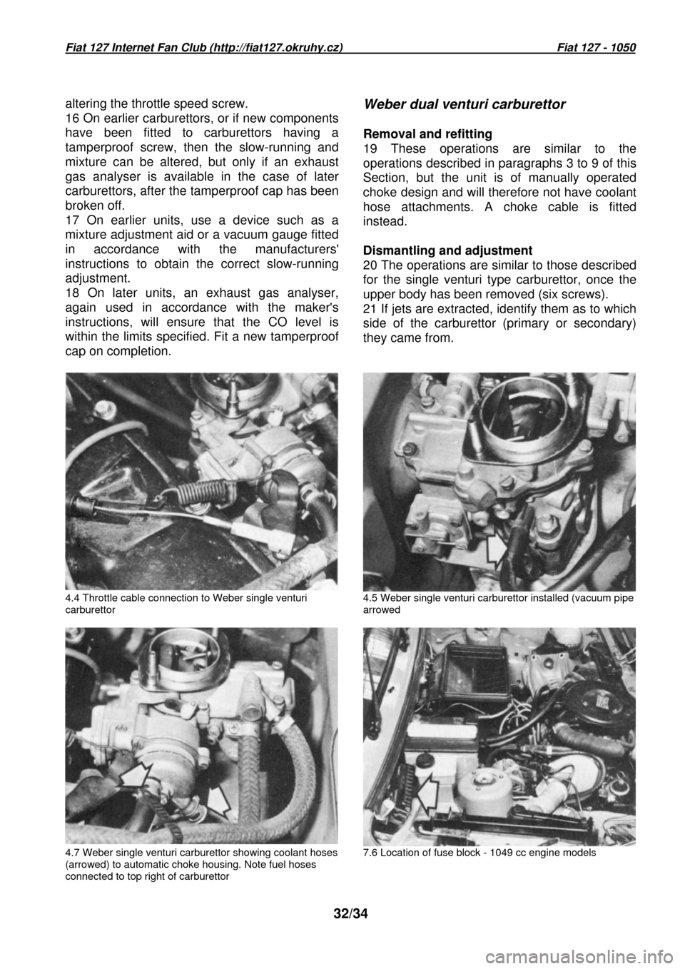
4.4 Throttle cable connection to Weber single ventu ri
carburettor 4.5 Weber single venturi carburettor installed (va
cuum pipe
arrowed
4.7 Weber single venturi carburettor showing coolan t hoses
(arrowed) to automatic choke housing. Note fuel hos es
connected to top right of carburettor 7.6 Location of fuse block - 1049 cc engine models