diagram FIAT 500 1957 1.G Owner's Manual
[x] Cancel search | Manufacturer: FIAT, Model Year: 1957, Model line: 500, Model: FIAT 500 1957 1.GPages: 128, PDF Size: 9.01 MB
Page 113 of 128

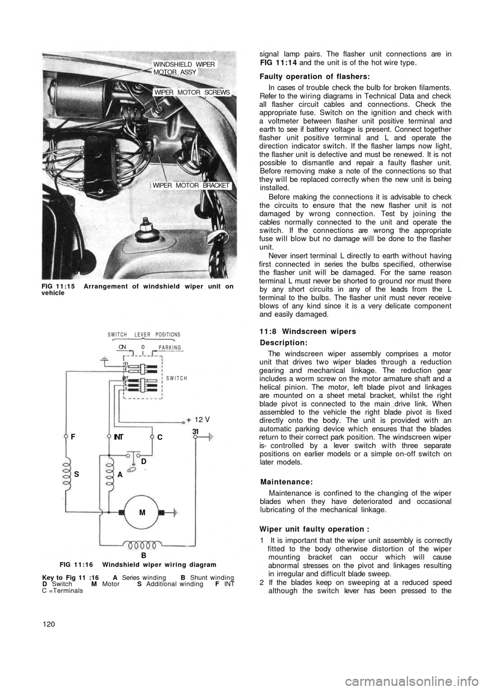
WINDSHIELD WIPER
MOTOR ASSY
WIPER MOTOR SCREWS
WIPER MOTOR BRACKET
FIG 11:15 Arrangement of windshield wiper unit on
vehicle
B M INT F
SC12 V
31
D
A
SWITCH PARKING
0 ON
SWITCH LEVER POSITIONS
FIG 11:16 Windshield wiper wiring diagram
Key to Fig 11 :16 A Series winding B Shunt winding
D Switch M Motor S Additional winding F INT
C =Terminals
120signal lamp pairs. The flasher unit connections are in
FIG 11:14 and the unit is of the hot wire type.
Faulty operation of flashers:
In cases of trouble check the bulb for broken filaments.
Refer to the wiring diagrams in Technical Data and check
all flasher circuit cables and connections. Check the
appropriate fuse. Switch on the ignition and check w i t h
a voltmeter between flasher unit positive terminal and
earth to see if battery voltage is present. Connect together
flasher unit positive terminal and L and operate the
direction indicator switch. If the flasher lamps now light,
the flasher unit is defective and must be renewed. It is not
possible to dismantle and repair a faulty flasher unit.
Before removing make a note of the connections so that
they will be replaced correctly when the new unit is being
installed.
Before making the connections it is advisable to check
the circuits to ensure that the new flasher unit is not
damaged by wrong connection. Test by joining the
cables normally connected to the unit and operate the
switch. If the connections are wrong the appropriate
fuse will blow but no damage will be done to the flasher
unit.
Never insert terminal L directly to earth without having
first connected in series the bulbs specified, otherwise
the flasher unit will be damaged. For the same reason
terminal L must never be shorted to ground nor must there
by any short circuits in any of the leads from the L
terminal to the bulbs. The flasher unit must never receive
blows of any kind since it is a very delicate component
and easily damaged.
11:8 Windscreen wipers
Description:
The windscreen wiper assembly comprises a motor
unit that drives t w o wiper blades through a reduction
gearing and mechanical linkage. The reduction gear
includes a worm screw on the motor armature shaft and a
helical pinion. The motor, left blade pivot and linkages
are mounted on a sheet metal bracket, whilst the right
blade pivot is connected to the main drive link. When
assembled to the vehicle the right blade pivot is fixed
directly onto the body. The unit is provided w i t h an
automatic parking device which ensures that the blades
return to their correct park position. The w
indscreen wiper
is- controlled by a lever switch with three separate
positions on earlier models or a simple on-off switch on
later models.
Maintenance:
Maintenance is confined to the changing of the wiper
blades when they have deteriorated and occasional
lubricating of the mechanical linkage.
Wiper unit faulty operation :
1 It is important that the wiper unit assembly is correctly
fitted to the body otherwise distortion of the wiper
mounting bracket can occur which will cause
abnormal stresses on the pivot and linkages resulting
in irregular and difficult blade sweep.
2 If the blades keep on sweeping at a reduced speed
although the switch lever has been pressed to the
Page 127 of 128

BOW
FIG 12:17 Sun Roof top in unlatched position
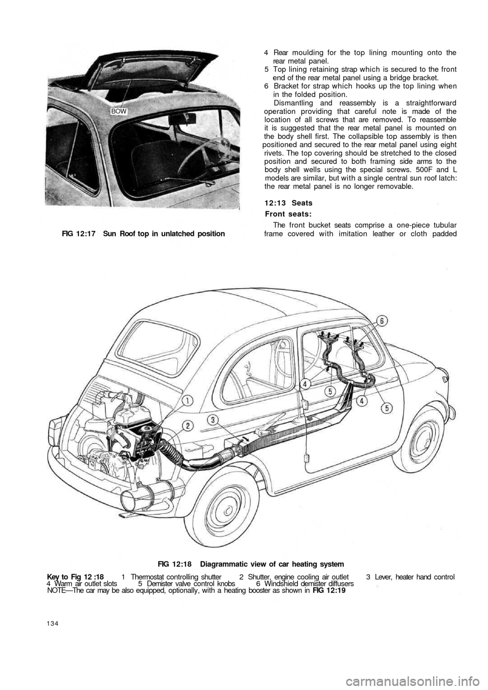
FIG 12:18 Diagrammatic view of car heating system
Key to Fig 12 :18 1 Thermostat controlling shutter 2 Shutter, engine cooling air outlet 3 Lever, heater hand control
4 Warm air outlet slots 5 Demister valve control knobs 6 Windshield demister diffusers
NOTE—The car may be also equipped, optionally, with a heating booster as shown in FIG 12:19
134
4 Rear moulding for the top lining mounting onto the
rear metal panel.
5 Top lining retaining strap which is secured to the front
end of t h e rear metal panel using a bridge bracket.
6 Bracket for strap which hooks up the top lining when
in the folded position.
Dismantling and reassembly is a straightforward
operation providing that careful note is made of the
location of all screws that are removed. To reassemble
it is suggested that the rear metal panel is mounted on
the body shell first. The collapsible top assembly is then
positioned and secured to the rear metal panel using eight
rivets. The top covering should be stretched to the closed
position and secured to both framing side arms to t h e
body shell wells using the special screws. 500F and L
models are similar, but with a single central sun roof latch:
t h e rear metal panel is no longer removable.
12:13 Seats
Front seats:
The front bucket seats comprise a one-piece tubular
frame covered with imitation leather or cloth padded
Page 128 of 128

cushion and back rest. A number of rubber straps are
hooked across the frame under the cushion and in a
sheath covering on the seat back.
The bottom of the front seat frame ends are provided
with sliding guides which run in guide rails attached to
the floor. The sliding guides are pivoted on the frame
tubes to allow for forward tilting of the seats giving better
access to the rear compartment. Two rubber pads
provide cushioning of the seat frame on the guide rails
as shown in FIG 12:11. The control lever for seat
adjustment is fitted in the frame righthand tube to permit
unlocking of the seats so that they may be adjusted to
individual drivers requirements.
Rear seats (Sedan):
The rear seat comprises of a foam rubber cushion and
back. The seat back is cemented to the rear floor and
body shell bulkhead. The rear seat lining is of fabric and
imitation leather. The seat lining is held in place by four
self-tapping screws, t w o of which secure the floor below
the back window and two the lining at the base of t h e
back rest. Included with the seat assembly is a masonite
floor which is fitted below the rear window.
Rear Seat (Station Wagon):
The rear seat back rest is pivoted at the base of its
frame so that it can be folded down to form a load plat-
form surface. In the upright position it is retained in place
by t w o brackets mounted on either side of the body below
the side
windows.
12:14 Interior heater
Description:
Interior heating is accomplished by recirculation of
warm air from the engine cooling system through engine
cowling. Referring to FIG 12:18 a hose conveys warmed
air from the engine cowling to the centre tunnel floor
where warm air flows out through two slots being cut on
the windshield delivery hoses. Air admission can be
adjusted by turning the control lever to the right which
operates the tunnel throttle valve at the rear seat.
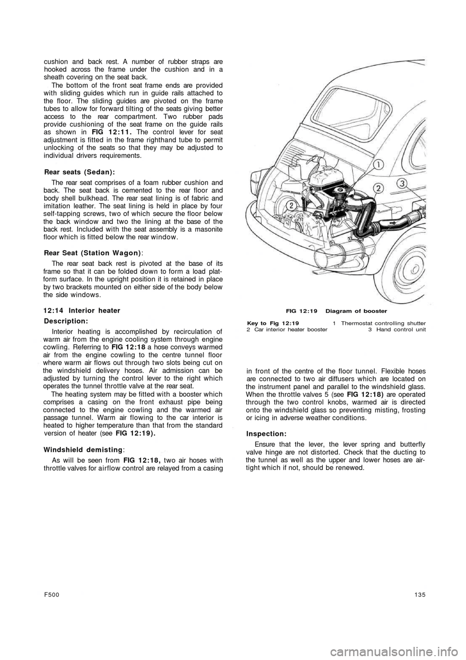
The heating system may be fitted with a booster which
comprises a casing on the front exhaust pipe being
connected to the engine cowling and the warmed air
passage tunnel. Warm air flowing to the car interior is
heated to higher temperature than that from the standard
version of heater (see FIG 12:19).
Windshield demisting:
As will be seen from FIG 12:18, t w o air hoses w i t h
throttle valves for airflow control are relayed from a casing
F500135
FIG 12:19 Diagram of booster
Key to Fig 12:19 1 Thermostat controlling shutter
2 Car interior heater booster 3 Hand control unit
in front of the centre of the floor tunnel. Flexible hoses
are connected to two air diffusers which are located on
the instrument panel and parallel to the windshield glass.
When the throttle valves 5 (see FIG 12:18) are operated
through the two control knobs, warmed air is directed
onto the windshield glass so preventing misting, frosting
or icing in adverse weather conditions.
Inspection:
Ensure that t h e lever, the lever spring and butterfly
valve hinge are not distorted. Check that the ducting to
the tunnel as well as the upper and lower hoses are air-
tight which if not, should be renewed.