diagram FIAT 500 1957 1.G User Guide
[x] Cancel search | Manufacturer: FIAT, Model Year: 1957, Model line: 500, Model: FIAT 500 1957 1.GPages: 128, PDF Size: 9.01 MB
Page 49 of 128
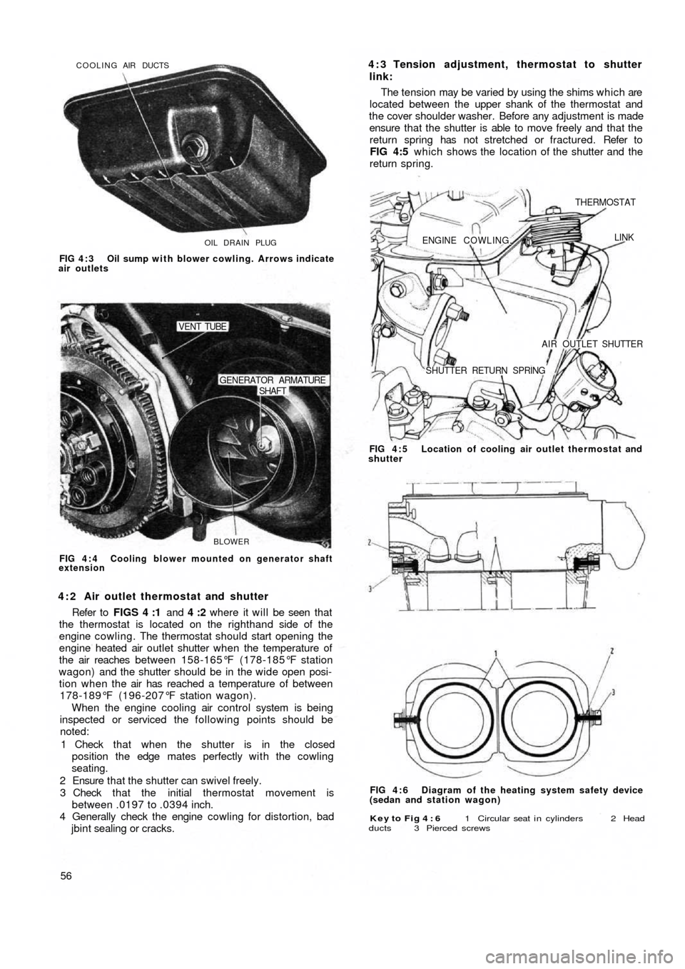
OIL DRAIN PLUG COOLING AIR DUCTS
FIG 4 : 3 Oil sump with blower cowling. Arrows indicate
air outlets
BLOWER
SHAFT GENERATOR ARMATURE
VENT TUBE
FIG 4 : 4 Cooling blower mounted on generator shaft
extension
4 : 2 Air outlet thermostat and shutter
Refer to FIGS 4 :1 and 4 :2 where it will be seen that
the thermostat is located on the righthand side of the
engine cowling. The thermostat should start opening the
engine heated air outlet shutter when the temperature of
the air reaches between 158-165°F (178-185°F station
wagon) and the shutter should be in the wide open posi-
tion when the air has reached a temperature of between
178-189°F (196-207°F station wagon).
When the engine cooling air control system is being
inspected or serviced the following points should be
noted:
1 Check that when the shutter is in the closed
position the edge mates perfectly with the cowling
seating.
2 Ensure that the shutter can swivel freely.
3 Check that the initial thermostat movement is
between .0197 to .0394 inch.
4 Generally check the engine cowling for distortion, bad
jbint sealing or cracks.
56
Key to Fig 4 : 6 1 Circular seat i n cylinders 2 Head
ducts 3 Pierced screws
FIG 4 : 6 Diagram of the heating system safety device
(sedan and station wagon) FIG 4 : 5 Location of cooling air outlet thermostat and
shutter
ENGINE COWLING.
THERMOSTAT
LINK
AIR OUTLET SHUTTER
SHUTTER RETURN SPRING
4 : 3 Tension adjustment, thermostat to shutter
link:
The tension may be varied by using the shims which are
located between the upper shank of the thermostat and
the cover shoulder washer. Before any adjustment is made
ensure that the shutter is able to move freely and that the
return spring has not stretched or fractured. Refer to
FIG 4:5 which shows the location of the shutter and the
return spring.
Page 55 of 128
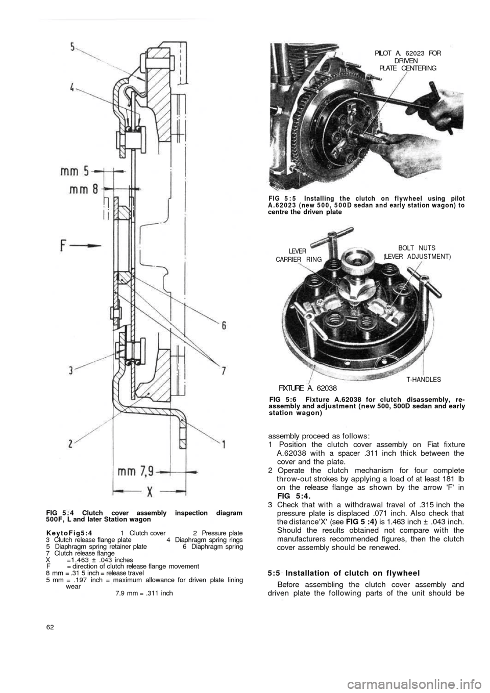
FIG 5 . 4 Clutch cover assembly inspection diagram
500F, L and later Station wagon
KeytoFig5:4 1 Clutch cover 2 Pressure plate
3 Clutch release flange plate 4 Diaphragm spring rings
5 Diaphragm spring retainer plate 6 Diaphragm spring
7 Clutch release flange
X =1.463 ± .043 inches
F = direction of clutch release flange movement
8 mm = .31 5 inch = release travel
5 mm = .197 inch = maximum allowance for driven plate lining
wear7.9 mm = .311 inch
62
5:5 Installation of clutch on flywheel
Before assembling the clutch cover assembly and
driven plate the following parts of the unit should be assembly proceed as follows:
1 Position the clutch cover assembly on Fiat fixture
A.62038 with a spacer .311 inch thick between the
cover and the plate.
2 Operate the clutch mechanism for four complete
throw-out strokes by applying a load of at least 181 Ib
on the release flange as shown by the arrow 'F' in
FIG 5:4.
3 Check that w i t h a withdrawal travel of .315 inch the
pressure plate is displaced .071 inch. Also check that
the distance'X' (see FIG 5 :4) is 1.463 inch ± .043 inch.
Should the results obtained not compare w i t h the
manufacturers recommended figures, then the clutch
cover assembly should be renewed.
FIG 5:6 Fixture A.62038 for clutch disassembly, re-
assembly and adjustment (new 500, 500D sedan and early
station wagon)
FIXTURE A . 62038
T-HANDLES CARRIER RING
LEVERBOLT NUTS
(LEVER ADJUSTMENT) FIG 5 : 5 Installing the clutch on flywheel using pilot
A.62023 (new 500, 500D sedan and early station wagon) to
centre the driven platePILOT A. 62023 FOR
DRIVENPLATE CENTERING
Page 66 of 128
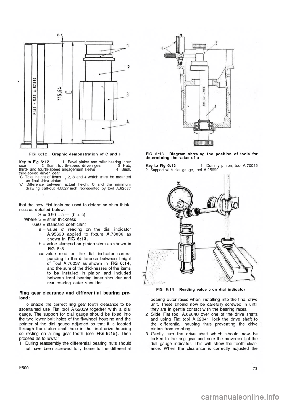
FIG 6:12 Graphic demonstration of C and c
Key to Fig 6:12 1 Bevel pinion rear roller bearing inner
race 2 Bush, fourth-speed driven gear 3 Hub,
third- and fourth-speed engagement sleeve 4 Bush,
third-speed driven gear
'C Total height of items 1, 2, 3 and 4 which must be mounted
on final drive pinion
'c' Difference between actual height C and the minimum
drawing call-out 4.5527 inch represented by tool A.62037
that the new Fiat tools are used to determine shim thick-
ness as detailed below:
S = 0.90 + a — (b + c)
Where S = shim thickness
0.90 = standard coefficient
a = value of reading on the dial indicator
A.95690 applied to fixture A.70036 as
shown in FIG 6:13.
b = value stamped on pinion stem as shown in
FIG 6:8.
c= value read o n the dial indicator corres-
ponding to the difference between height
of Tool A.70037 as shown in FIG 6:14,
and the sum of the thicknesses of the items
to be installed in pinion and included
between front bearing inner shoulder and
rear bearing outer shoulder.
Ring gear clearance and differential bearing pre-
load :
To enable the correct ring gear tooth clearance to be
ascertained use Fiat tool A.62039 together with a dial
gauge. The support for dial gauge should be fixed into
the t w o lower bolt holes of the flywheel housing and the
pointer of the dial gauge adjusted so that it is located
through the clutch shaft hole in the final drive housing
so resting on a ring gear tooth (see FIG 6:15). Then
proceed as follows:
1 During reassembly the differential bearing nuts should
not have been screwed fully home to the differential
F50073
bearing outer races w h e n installing into the f i n a l drive
unit. These should now be carefully screwed in until
they are in gentle contact with the bearing races.
2 Slide Fiat tool A.62040 over one of the drive shafts
and using Fiat tool A.62041 lock the drive shaft to
the differential housing thus preventing the drive
pinion from rotating.
3 Gently turn the drive shaft which should now be
locked to the ring gear and note the movement of the
dial gauge indicator. This will show the tooth clear-
ance. When the clearance is correctly adjusted the
FIG 6:14 Reading value c on dial indicator Key to Fig 6:13 1 Dummy pinion, tool A.70036
2 Support with dial gauge, tool A.95690 FIG 6:13 Diagram showing the position of tools for
determining the value of a
Page 94 of 128
reassembling and during assembly liberally lubricated
using Fiat W90/M oil (SAE90 EP).
2 The pitman arm nut should be correctly positioned on
reassembly to the sector shaft and both are marked
with notches or a master tooth on the sector will mate
with a double tooth on the pitman arm which will
prevent incorrect reassembly.
3 The pitman arm nut must be tightened to a torque
wrench setting of 72 Ib/ft.
4 Fill the box up to the level and filler plug with SAE90 EP
gear oil.
Refitting the steering box:
To refit the steering box to the vehicle proceed as
follows:
1 Engage the w o r m screw f r o m the steering shaft by
gently manipulating the steering box.
2 Replace the steering box to body nuts and tighten to a
torque wrench setting of 14 to 18 Ib/ft.
3 Replace the t w o track rod pins in their seatings in the
pitman arm and tighten the self-locking nuts to a
torque wrench setting of 18 to 21 Ib/ft.
4 Replace the steering shaft to worm screw mounting
bolt, lock washer and nut.
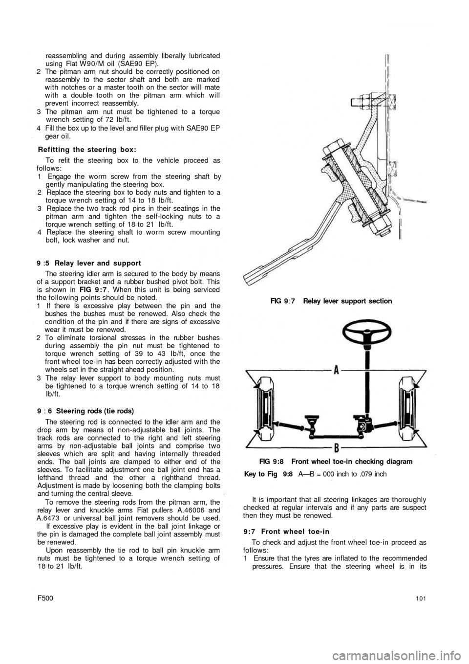
9 :5 Relay lever and support
The steering idler arm is secured to the body by means
of a support bracket and a rubber bushed pivot bolt. This
is shown in FIG 9 : 7. When this unit is being serviced
the following points should be noted.
1 If there is excessive play between the pin and the
bushes the bushes must be renewed. Also check the
condition of the pin and if there are signs of excessive
wear it must be renewed.
2 To eliminate torsional stresses in the rubber bushes
during assembly the pin nut must be tightened to
torque wrench setting of 39 to 43 Ib/ft, once the
front wheel toe-in has been correctly adjusted w i t h the
wheels set in the straight ahead position.
3 The relay lever support to body mounting nuts must
be tightened to a torque wrench setting of 14 to 18
Ib/ft.
9 : 6 Steering rods (tie rods)
The steering rod is connected to the idler arm and the
drop arm by means of non-adjustable ball joints. The
track rods are connected to the right and left steering
arms by non-adjustable ball joints and comprise t w o
sleeves which are split and having internally threaded
ends. The ball joints are clamped to either end of the
sleeves. To facilitate adjustment one ball joint end has a
lefthand thread and the other a righthand thread.
Adjustment is made by loosening both the clamping bolts
and turning the central sleeve.
To remove the steering rods from the pitman arm, the
relay lever and knuckle arms Fiat pullers A.46006 and
A.6473 or universal ball joint removers should be used.
If excessive play is evident in the ball joint linkage or
the pin is damaged the complete ball joint assembly must
be renewed.
Upon reassembly the tie rod to ball pin knuckle arm
nuts must be tightened to a torque wrench setting of
18 to 21 Ib/ft.
F500101
FIG 9:7 Relay lever support section
FIG 9:8 Front wheel toe-in checking diagram
Key to Fig 9:8 A—B = 000 inch to .079 inch
It is important that all steering linkages are thoroughly
checked at regular intervals and if any parts are suspect
then they must be renewed.
9 : 7 Front wheel toe-in
To check and adjust the front wheel toe-in proceed as
follows:
1 Ensure that the tyres are inflated to the recommended
pressures. Ensure that the steering wheel is in its
Page 97 of 128
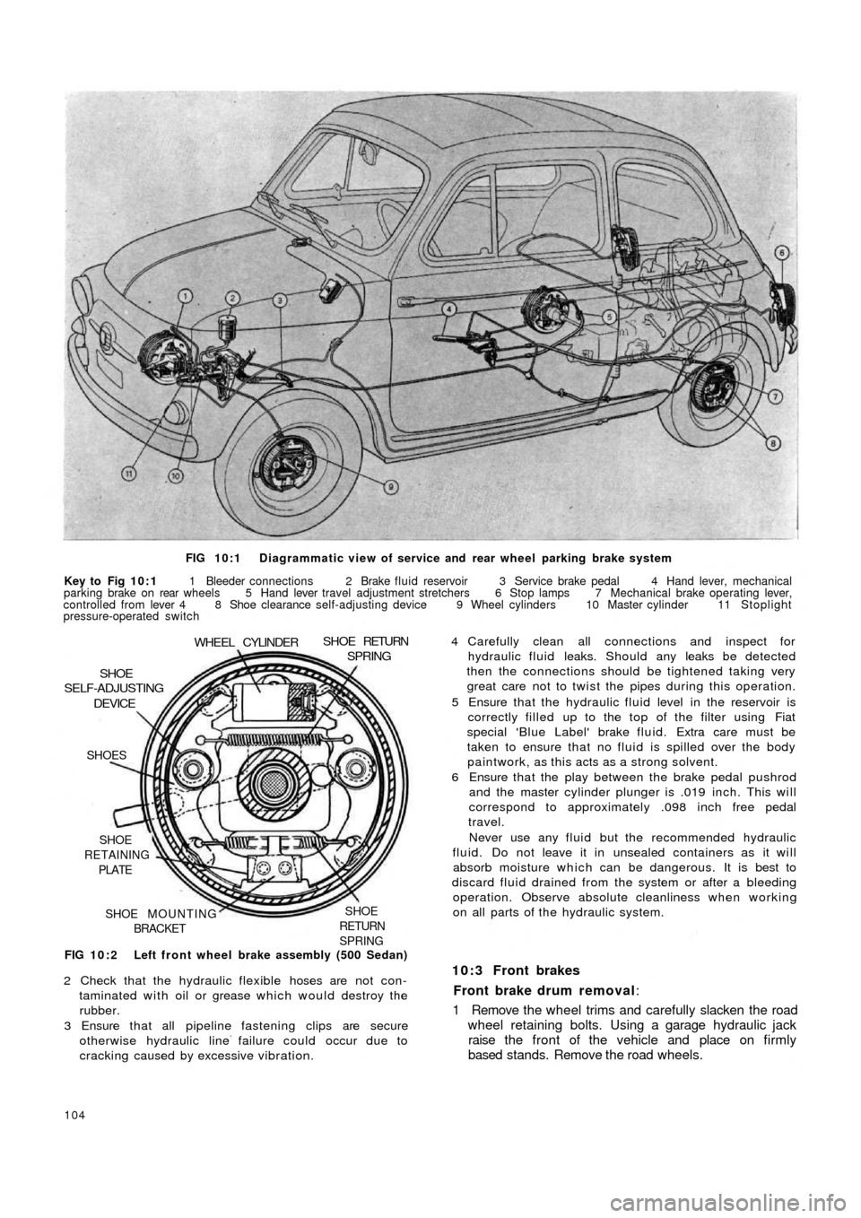
FIG 10:1 Diagrammatic view of service and rear wheel parking brake system
Key to Fig 10:1 1 Bleeder connections 2 Brake fluid reservoir 3 Service brake pedal 4 Hand lever, mechanical
parking brake on rear wheels 5 Hand lever travel adjustment stretchers 6 Stop lamps 7 Mechanical brake operating lever,
controlled from lever 4 8 Shoe clearance self-adjusting device 9 Wheel cylinders 10 Master cylinder 11 Stoplight
pressure-operated switch
FIG 10:2 Left front wheel brake assembly (500 Sedan)
SHOE
RETURN
SPRINGSHOE MOUNTING
BRACKET SHOE
RETAINING
PLATE SHOES
DEVICESHOE
SELF-ADJUSTING
WHEEL CYLINDERSHOE RETURNSPRING
2 Check that the hydraulic flexible hoses are not con-
taminated with oil or grease which would destroy the
rubber.
3 Ensure that all pipeline fastening clips are secure
otherwise hydraulic line failure could occur due to
cracking caused by excessive vibration.
104
4 Carefully clean all connections and inspect for
hydraulic fluid leaks. Should any leaks be detected
then the connections should be tightened taking very
great care not to twist the pipes during this operation.
5 Ensure that the hydraulic fluid level in the reservoir is
correctly filled up to the top of the filter using Fiat
special 'Blue Label' brake fluid. Extra care must be
taken to ensure that no fluid is spilled over the body
paintwork, as this acts as a strong solvent.
6 Ensure that the play between the brake pedal pushrod
and the master cylinder plunger is .019 inch. This will
correspond to approximately .098 inch free pedal
travel.
Never use any fluid but the recommended hydraulic
fluid. Do not leave it in unsealed containers as it will
absorb moisture which can be dangerous. It is best to
discard fluid drained from the system or after a bleeding
operation. Observe absolute cleanliness when working
on all parts of the hydraulic system.
10:3 Front brakes
Front brake drum removal:
1 Remove the wheel trims and carefully slacken the road
wheel retaining bolts. Using a garage hydraulic jack
raise the front of the vehicle and place on firmly
based stands. Remove the road wheels.
Page 104 of 128
CHAPTER 11
THE ELECTRICAL EQUIPMENT
11:1 Description
11:2 Battery
11:3 The generator
11:4 The starter
11:5 The control box
1 1 : 6 Fuses
1 1 : 7 Flasher unit
11:1 Description
All models covered by this manual have 12 volts
electrical systems in which the negative battery terminal
is earthed. There are three units in the regulator box to
control the charging circuit; a cut-out, a current regulator
and a voltage regulator. These are adjustable but it must
be stressed that accurate moving coil meters are required
when checking or altering the settings. Cheap and
unreliable instruments will make accurate adjustments
impossible.
There are wiring diagrams in Technical Data at the end
of this manual to enable those with electrical experience
to trace and correct wiring faults.
For t h e U.K. Market the headlamps are of the double
filament dipping renewable bulb type with adjustments
for individual beam settings.
The battery is located in the front compartment
forward of the petrol tank and the fuses to the rear o f the
petrol tank.
Detailed instructions for servicing the electrical equip-
ment will be found in this chapter, but it must be pointed
out that it is not sensible to try to repair that which is
seriously defective, electrically or mechanically. Such
equipment should be replaced by new units which can
be obtained on an exchange basis.
F500111
11 :8 Windscreen wipers
1 1 : 9 The lighting system
11:10 Panel and warning lights
11:11 The horn
11:12 Lighting and flasher switch
1 1 : 1 3 Fault diagnosis
11.2 The battery
This of the 12-volt lead/acid type and has to meet
heavy demands for current particularly in the winter. To
maintain the performance of the battery at its maximum
it is essential to carry out the following operations.
Keep the top of the battery and surrounding parts dry
and clean, as dampness can cause leakage between the
securing clamps and the battery terminals. Clean off any
corrosion from the metal parts of the battery mounting
with diluted ammonia and paint them with an anti-
sulphuric paint. If the terminal posts are corroded,
remove the cables and clean w i t h diluted ammonia.
Smear the posts w i t h petroleum jelly before remaking the
connections and fit the terminals securely. High electrical
resistance due to corrosion at the terminal posts is often
responsible for lack of sufficient current to operate the
starter motor.
Ensure t h a t the filler plugs are in good condition and
show no signs of cracks. This may cause leakage of
electrolyte and consequent corrosion. Test the condition
of the cells after topping-up the electrolyte level with
distilled water to just above the tops of the separators as
shown in FIG 11 :2 . Never add neat acid. If it is
necessary to make a new electrolyte due to loss by
spillage add sulphuric acid to the
distilled water.
It is highly dangerous to add water to acid.
Page 109 of 128
4
53 2 1
7
6
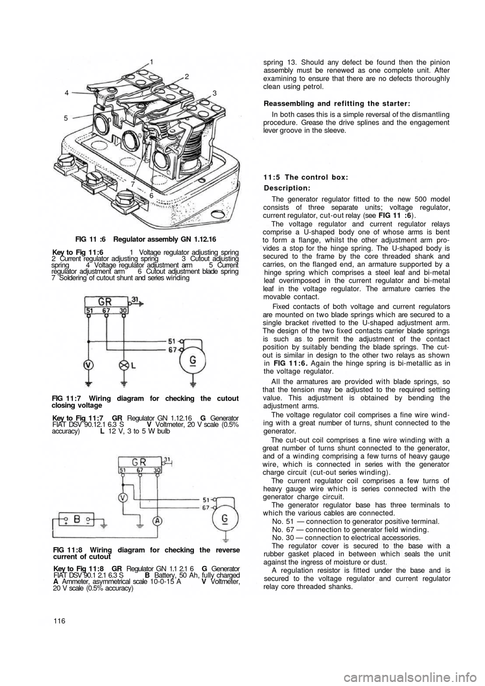
FIG 11 :6 Regulator assembly GN 1.12.16
Key to Fig 11:6 1 Voltage regulator adjusting spring
2 Current regulator adjusting spring 3 Cutout adjusting
spring 4 Voltage regulator adjustment arm 5 Current
regulator adjustment arm 6 Cutout adjustment blade spring
7 Soldering of cutout shunt and series winding
FIG 11:7 Wiring diagram for checking the cutout
closing voltage
Key to Fig 1 1 : 7 GR Regulator GN 1.12.16 G Generator
FIAT DSV 90.12.1 6.3 S V Voltmeter, 20 V scale (0.5%
accuracy) L 12 V, 3 to 5 W bulb
FIG 11:8 Wiring diagram for checking the reverse
current of cutout
Key to Fig 11:8 GR Regulator GN 1.1 2.1 6 G Generator
FIAT DSV 90.1 2.1 6.3 S B Battery, 50 Ah, fully charged
A Ammeter, asymmetrical scale 10-0-15 A V Voltmeter,
20 V scale (0.5% accuracy)
116spring 13. Should any defect be found then the pinion
assembly must be renewed as one complete unit. After
examining to ensure that there are no defects thoroughly
clean using petrol.
Reassembling and refitting the starter:
In both cases this is a simple reversal of the dismantling
procedure. Grease t h e drive splines and the engagement
lever groove in the sleeve.
11:5 The control box:
Description:
The generator regulator fitted to the new 500 model
consists of three separate
units; voltage regulator,
current regulator, cut-out relay (see FIG 11 :6).
The voltage regulator and current regulator relays
comprise a U-shaped body one of whose arms is bent
to form a flange, whilst the other adjustment arm pro-
vides a stop for the hinge spring. The U-shaped body is
secured to the frame by the core threaded shank and
carries, on the flanged end, an armature supported by a
hinge spring which comprises a steel leaf and bi-metal
leaf overimposed in the current regulator and bi-metal
leaf in the voltage regulator. The armature carries the
movable contact.
Fixed contacts of both voltage and current regulators
are mounted on t w o blade springs which are secured to a
single bracket rivetted to the U-shaped adjustment arm.
The design of the t w o fixed contacts carrier blade springs
is such as to permit the adjustment of the contact
position by suitably bending the blade springs. The cut-
out is similar in design to the other two relays as shown
in FIG 11:6. Again the hinge spring is bi-metallic as in
the voltage regulator.
All the armatures are provided w i t h blade springs, so
that the tension may be adjusted to the required setting
value. This adjustment is obtained by bending the
adjustment arms.
The voltage regulator coil comprises a fine wire wind-
ing w i t h a great number of turns, shunt connected to the
generator.
The cut-out coil comprises a fine wire winding with a
great number of turns shunt connected to the generator,
and of a winding comprising a few turns of heavy gauge
wire, which is connected in series w i t h the generator
charge circuit (cut-out series winding).
The current regulator coil comprises a few turns of
heavy gauge wire which is series connected with the
generator charge circuit.
The generator regulator base has three terminals to
which the various cables are connected.
No. 51 — connection to generator positive terminal.
No. 67 — connection to generator field winding.
No. 30 — connection to electrical accessories.
The regulator cover is secured to the base w i t h a
rubber gasket placed in between which seals the unit
against the ingress of moisture or dust.
A regulation resistor is fitted under the base and is
secured to the voltage regulator and current regulator
relay core threaded shanks.
Page 110 of 128
Checking cut-out:
1 Closing voltage:
This test should be carried out at a temperature of
25°±10°C and the regulator should be connected to a
generator test bed as shown in FIG 11:7. The unit should
be operated under no load conditions for between 15 -
18 minutes with the cover installed and w i t h a voltage of
between 16.5 volts for an initial operating temperature of
15-20°C or 15 volts for an initial operating temperature
of 20-35°C. This will enable thermal stabilization of the
unit to be obtained so that the temperature of both the
cut-out shunt windings and the bymetallic springs
increase due to the heat developed by the windings and
reaches the normal operating setting.
Once thermal stabilization has been obtained the
generator should be restarted and the speed gradually
increased so that immediately the test lamp starts to
glow the voltmeter reading may be taken. This will be
the value of the cut-out contact closing voltage.
2 Reverse current:
This check should be carried out at a temperature range
of between 25°±10°C and it is recommended that it is
performed as soon as possible after the closing voltage
test so that the thermal stabilization remains unaltered.
Connect the regulator as shown in FIG 11:8 and
gradually speed up the generator to 4500 rev/min for
approximately 5 minutes. Ensure that the voltmeter reads
at least 14.5 volts and then gradually reduce the generator
speed carefully watching the movement of the ammeter
needle which should at first indicate a charging current
and then gradually move to zero and then to the other side
of the scale to indicate reverse current value. If the
generator speed is reduced further the reverse current
reading will increase to a given value and then suddenly
fall to zero which will indicate that the cut-out contact
has opened. This limit indicates the maximum reverse
current value which should not, under any circumstances,
exceed 16 amps.
During this test, to obtain the maximum reverse
current possible the reduction in generator speed must
not take more than 10 seconds otherwise the battery
voltage will drop excessively.
Checking voltage regulator:
This test should be carried out w i t h the regulator under
half load and at a temperature of 50°± 3°C. Connect the
regulator as shown in FIG 11:9 and operate the regulator
for approximately 30 minutes by supplying a current half
that of regulated current which is 1 6 ±5 amp. Once the
regulator has been brought to the required temperature
stop the generator and start it again, gradually increasing
the speed to a maximum of 4500 rev/min. Adjust the
rheostat for a generator output corresponding to half load
current of 8 ± 2 amps. When this generator output has
been set the voltage should be 14.2± .3 volts.
Checking current regulator:
Leave the regulator connected as shown in
FIG 11 :10
and this test must be carried out immediately after testing
the half load regulated voltage of the voltage regulator
when connected to a battery. Check that the ammeter
fitted will accommodate a 40 amp deflection: if not a
F500117
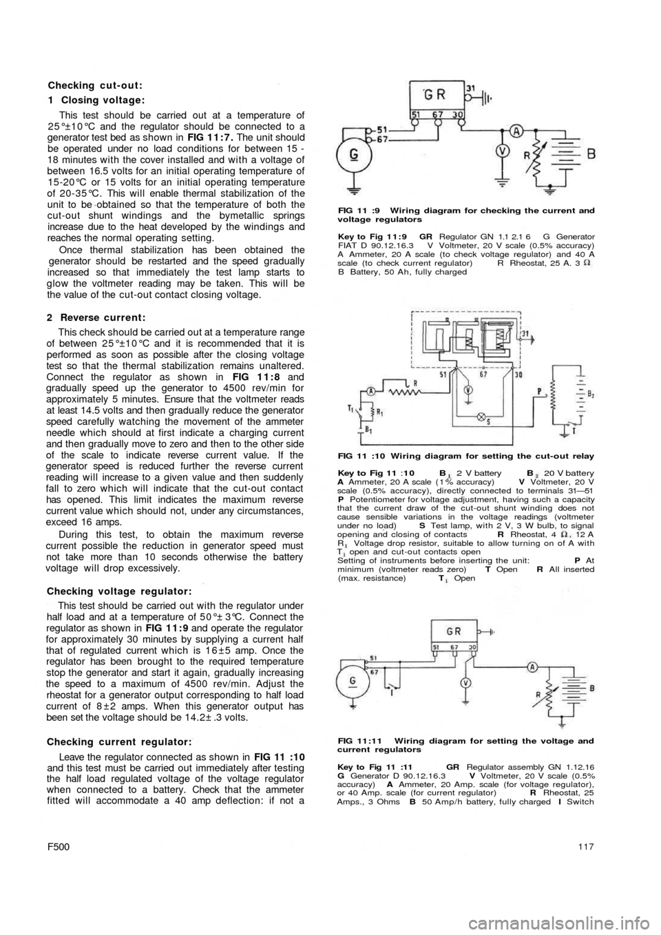
FIG 11 :9 Wiring diagram for checking the current and
voltage regulators
Key to Fig 11:9 GR Regulator GN 1.1 2.1 6 G Generator
FIAT D 90.12.16.3 V Voltmeter, 20 V scale (0.5% accuracy)
A Ammeter, 20 A scale (to check voltage regulator) and 40 A
scale (to check current regulator)
B Battery, 50 Ah, fully chargedR Rheostat, 25 A. 3
FIG 11 :10 Wiring diagram for setting the cut-out relay
Key to Fig 11 :10 B 2 V battery B 20 V batteryA Ammeter, 20 A scale ( 1 % accuracy) V Voltmeter, 20 V
scale (0.5% accuracy), directly connected to terminals 31—51
P Potentiometer for voltage adjustment, having such a capacity
that the current draw of the cut-out shunt winding does not
cause sensible variations in the voltage readings (voltmeter
under no load) S Test lamp, with 2 V, 3 W bulb, to signal
opening and closing of contacts R Rheostat, 4 12
AR Voltage drop resistor, suitable to allow turning on of A withT open and cut-out contacts open
Setting of instruments before inserting the unit: P At
minimum (voltmeter reads zero) T Open R All inserted
(max. resistance) T Open
FIG 11:11 Wiring diagram for setting the voltage and
current regulators
Key to Fig 11 :11 GR Regulator assembly GN 1.12.16
G Generator D 90.12.16.3 V Voltmeter, 20 V scale (0.5%
accuracy) A Ammeter, 20 Amp. scale (for voltage regulator),
or 40 Amp. scale (for current regulator) R Rheostat, 25
Amps., 3 Ohms B 50 Amp/h battery, fully charged I Switch
Page 111 of 128
Checking cut-out:
1 Closing voltage:
This test should be carried out at a temperature of
25°±10°C and the regulator should be connected to a
generator test bed as shown in FIG 11:7. The unit should
be operated under no load conditions for between 15 -
18 minutes with the cover installed and w i t h a voltage of
between 16.5 volts for an initial operating temperature of
15-20°C or 15 volts for an initial operating temperature
of 20-35°C. This will enable thermal stabilization of the
unit to be obtained so that the temperature of both the
cut-out shunt windings and the bymetallic springs
increase due to the heat developed by the windings and
reaches the normal operating setting.
Once thermal stabilization has been obtained the
generator should be restarted and the speed gradually
increased so that immediately the test lamp starts to
glow the voltmeter reading may be taken. This will be
the value of the cut-out contact closing voltage.
2 Reverse current:
This check should be carried out at a temperature range
of between 25°±10°C and it is recommended that it is
performed as soon as possible after the closing voltage
test so that the thermal stabilization remains unaltered.
Connect the regulator as shown in FIG 11:8 and
gradually speed up the generator to 4500 rev/min for
approximately 5 minutes. Ensure that the voltmeter reads
at least 14.5 volts and then gradually reduce the generator
speed carefully watching the movement of the ammeter
needle which should at first indicate a charging current
and then gradually move to zero and then to the other side
of the scale to indicate reverse current value. If the
generator speed is reduced further the reverse current
reading will increase to a given value and then suddenly
fall to zero which will indicate that the cut-out contact
has opened. This limit indicates the maximum reverse
current value which should not, under any circumstances,
exceed 16 amps.
During this test, to obtain the maximum reverse
current possible the reduction in generator speed must
not take more than 10 seconds otherwise the battery
voltage will drop excessively.
Checking voltage regulator:
This test should be carried out w i t h the regulator under
half load and at a temperature of 50°± 3°C. Connect the
regulator as shown in FIG 11:9 and operate the regulator
for approximately 30 minutes by supplying a current half
that of regulated current which is 1 6 ±5 amp. Once the
regulator has been brought to the required temperature
stop the generator and start it again, gradually increasing
the speed to a maximum of 4500 rev/min. Adjust the
rheostat for a generator output corresponding to half load
current of 8 ± 2 amps. When this generator output has
been set the voltage should be 14.2± .3 volts.
Checking current regulator:
Leave the regulator connected as shown in
FIG 11 :10
and this test must be carried out immediately after testing
the half load regulated voltage of the voltage regulator
when connected to a battery. Check that the ammeter
fitted will accommodate a 40 amp deflection: if not a
F500117
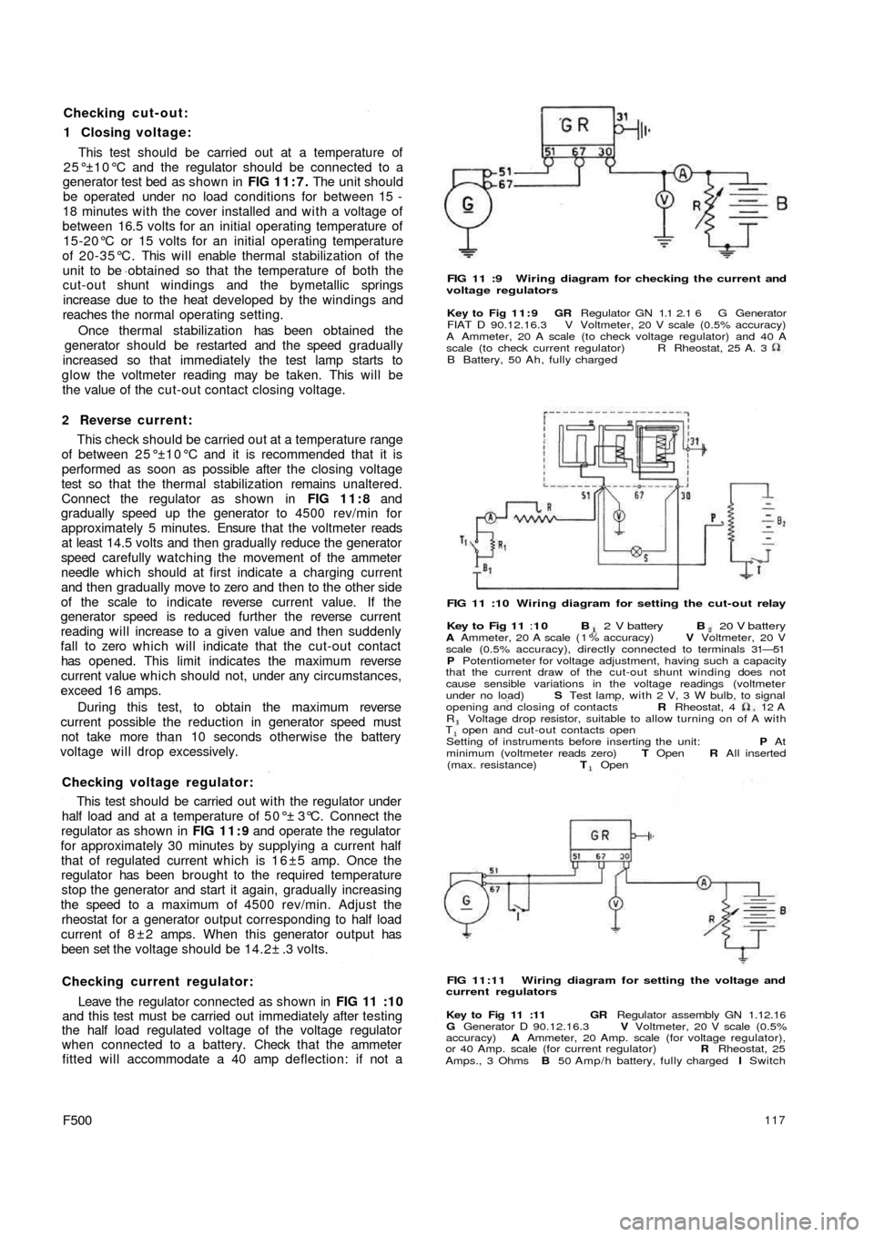
FIG 11 :9 Wiring diagram for checking the current and
voltage regulators
Key to Fig 11:9 GR Regulator GN 1.1 2.1 6 G Generator
FIAT D 90.12.16.3 V Voltmeter, 20 V scale (0.5% accuracy)
A Ammeter, 20 A scale (to check voltage regulator) and 40 A
scale (to check current regulator)
B Battery, 50 Ah, fully chargedR Rheostat, 25 A. 3
FIG 11 :10 Wiring diagram for setting the cut-out relay
Key to Fig 11 :10 B 2 V battery B 20 V batteryA Ammeter, 20 A scale ( 1 % accuracy) V Voltmeter, 20 V
scale (0.5% accuracy), directly connected to terminals 31—51
P Potentiometer for voltage adjustment, having such a capacity
that the current draw of the cut-out shunt winding does not
cause sensible variations in the voltage readings (voltmeter
under no load) S Test lamp, with 2 V, 3 W bulb, to signal
opening and closing of contacts R Rheostat, 4 12
AR Voltage drop resistor, suitable to allow turning on of A withT open and cut-out contacts open
Setting of instruments before inserting the unit: P At
minimum (voltmeter reads zero) T Open R All inserted
(max. resistance) T Open
FIG 11:11 Wiring diagram for setting the voltage and
current regulators
Key to Fig 11 :11 GR Regulator assembly GN 1.12.16
G Generator D 90.12.16.3 V Voltmeter, 20 V scale (0.5%
accuracy) A Ammeter, 20 Amp. scale (for voltage regulator),
or 40 Amp. scale (for current regulator) R Rheostat, 25
Amps., 3 Ohms B 50 Amp/h battery, fully charged I Switch
Page 112 of 128
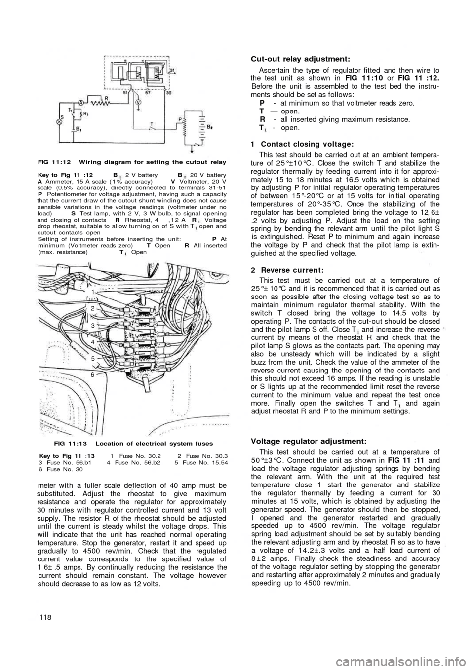
FIG 11:12 Wiring diagram for setting the cutout relay
Key to Fig 11 :12 B 2 V battery B 20 V battery
A Ammeter, 15 A scale ( 1 % accuracy) V Voltmeter, 20 V
scale (0.5% accuracy), directly connected to terminals 31-51
P Potentiometer for voltage adjustment, having such a capacity
that the current draw of the cutout shunt winding does not cause
sensible variations in the voltage readings (voltmeter under no
load) S Test lamp, with 2 V, 3 W bulb, to signal opening
and closing of contacts R Rheostat, 4 , 1 2 A R Voltagedrop rheostat, suitable to allow turning on of S with T open and
cutout contacts open
Setting of instruments before inserting the unit: P At
minimum (Voltmeter reads zero) T Open R All inserted
(max. resistance) T Open
1
2
3
4
5
6
FIG 11:13 Location of electrical system fuses
Key to Fig 11 :13 1 Fuse N o . 30.2 2 Fuse N o . 30.3
3 Fuse N o . 56.b1 4 Fuse N o . 56.b2 5 Fuse N o . 15.54
6 Fuse N o . 30
meter w i t h a fuller scale deflection of 40 amp must be
substituted. Adjust the rheostat to give maximum
resistance and operate the regulator for approximately
30 minutes with regulator controlled current and 13 volt
supply. The resistor R of the rheostat should be adjusted
until the current is steady whilst the voltage drops. This
will indicate that the unit has reached normal operating
temperature. Stop the generator, restart it and speed up
gradually to 4500 rev/min. Check that the regulated
current value corresponds to the specified value of
1 6± .5 amps. By continually reducing the resistance the
current should remain constant. The voltage however
should decrease to as l o w as 12 volts.
118
Cut-out relay adjustment:
Ascertain the type of regulator fitted and then wire to
the test unit as shown in FIG 11:10 or FIG 11 :12.
Before the unit is assembled to the test bed the instru-
ments should be set as follows:
P - at minimum so that voltmeter reads zero.
T — open.
R - all inserted giving maximum resistance.
T - open.
1 Contact closing voltage:
This test should be carried out at an ambient tempera-
ture of 25°±10°C. Close the switch T and stabilize the
regulator thermally by feeding current into it for approxi-
mately 15 to 18 minutes at 16.5 volts which is obtained
by adjusting P for initial regulator operating temperatures
of between 15°-20°C or at 15 volts for initial operating
temperatures of 20°-35°C. Once the stabilizing of the
regulator has been completed bring the voltage to 12 6±
.2 volts by adjusting P. Adjust the load on the setting
spring by bending the relevant arm until the pilot light S
is extinguished. Reset P to m inimum and again increase
the voltage by P and check that the pilot lamp is extin-
guished at the specified voltage.
2 Reverse current:
This test must be carried out at a temperature of
25°± 10°C and it is recommended that it is carried out as
soon as possible after the closing voltage test so as to
maintain minimum regulator thermal stability. With the
switch T closed bring the voltage to 14.5 volts by
operating P. The contacts of the cut-out should be closed
and the pilot lamp S off. Close T and increase the reverse
current by means of the rheostat R and check that the
pilot lamp S glows as the contacts part. The opening may
also be unsteady which will be indicated by a slight
buzz from the unit. Check the value of the ammeter of the
reverse current causing the opening of the contacts and
this should not exceed 16 amps. If the reading is unstable
or S lights up at the recommended limit reset the reverse
current to the minimum value and repeat the test once
more. Finally open the switches T and T and again
adjust rheostat R and P to the minimum settings.
Voltage regulator adjustment:
This test should be carried out at a temperature of
5 0 ° ±3 ° C . Connect the unit as shown in FIG 11 :11 and
load the voltage regulator adjusting springs by bending
the relevant arm. With the unit at the required test
temperature close 1 start the generator and stabilize
the regulator thermally by feeding a current for 30
minutes at 15 volts, which is obtained by adjusting the
generator speed. The generator should then be stopped,
I opened and the generator restarted and gradually
speeded up to 4500 rev/min. The voltage regulator
spring load adjustment should be set by suitably bending
the relevant adjusting arm and by rheostat R so as to have
a voltage of 14.2±.3 volts and a half load current of
8 ± 2 amps. Finally check the steadiness and accuracy
of the voltage regulator setting by stopping the generator
and restarting after approximately 2 minutes and gradually
speeding up to 4500 rev/min.