relay FIAT 500 1959 1.G Workshop Manual
[x] Cancel search | Manufacturer: FIAT, Model Year: 1959, Model line: 500, Model: FIAT 500 1959 1.GPages: 128, PDF Size: 9.01 MB
Page 24 of 128
sections of the air conveyor securing with seven
screws, seven toothed washers and five nuts.
22 Slide the fuel pump control rod into its seating,
assemble the insulator between oil wetted graphite
gaskets and fit the pump to the crankcase using nuts
and toothed washers.
23 Fit the air conveyor cover complete with the accelera-
tor control relay lever and rod. Secure using eight
mounting screws, eight toothed washers, eight plain
washers and eight nuts. Fit the fuel line retaining clip
which is secured by one of the air conveyor upper
screws. Install the generator and fan drive pulley
having first placed four adjusting rings between the
pulley halves and the thrust ring on the outside.
Secure the pulley to generator shaft using three
screws and three toothed washers. Fit the generator
fan drive belt.
24 Refit the carburetter having first positioned the
bakelite heat shield between the t w o oil moistened
graphite gaskets. Secure the carburetter using t w o
copper washers and t w o self-locking nuts. Fit the
exhaust silencer and secure to the exhaust manifolds
with nuts and spring washers. Place the t w o graphite
gaskets between the manifold joints. Fit both exhaust
silencer upper mounting brackets and secure them
on the top side to the brackets already in place w i t h
nuts and toothed washers on the bottom side w i t h
screws and toothed washers.
25 Carefully position the distributor at a 10 deg advance
setting and secure w i t h a
nut, plain washer and
spring washer. Fit the fuel pump to carburetter line
complete w i t h mounting bracket rubber lining and
secure the line with two clamps. If difficulty is
experienced in positioning the fuel line into the pump
or carburetter funnels it is suggested that the line
ends should be heated in hot water and thoroughly
dried before installing.
26 Install the air cleaner elbow and rubber hose assembly
on the top of the carburetter using a graphite gasket
in between and secure w i t h nuts, plain washers and
spring washers. Carefully position the air cleaner, line
and hose assembly and connect it to the elbow.
Secure the cleaner to air conveyor cover using screws
and toothed washers.
27 Fit the spark plug cables complete with the rubber
grommet for cable mounting bracket on engine
cowling and connect the cables to the distributor
and spark plugs. Fit the oil pressure gauge sender
unit together w i t h its sealing washer.
28 Install the cylinder head cover and oil breather pipe
assembly w i t h a cork gasket inserted between.
Secure w i t h self-locking nuts and fibre washers.
Connect the accelerator control relay lever rod to the
carburetter and secure with the clip.
29 Fill the oil pan with the correct grade and quantity of
oil, insert the dipstick and the engine is ready for
refitting.
1:18 Engine assembly (station wagon)
Reassembly of this engine is straightforward as it is
the reverse procedure to dismantling. It is recommended
that Sections 1 :5 and 1 :17 are studied as the assembly
technique is similar for both the horizontal and vertical
F50031 cylinder engines. The following points should however
be noted:
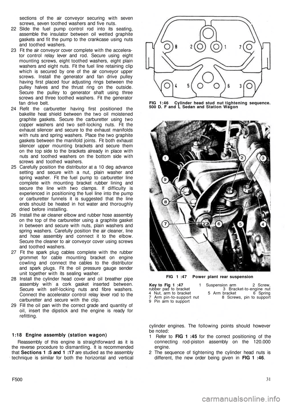
1 Refer to FIG 1 :45 for the correct positioning of the
connecting rod-piston assembly on the 120.000
engine.
2 The sequence of tightening the cylinder head nuts is
different, the new order being given in FIG 1 :46.
Key to Fig 1 :47 1 Suspension arm 2 Screw,
rubber pad to bracket 3 Bracket-to-engine nut
4 Nut, arm to bracket 5 Arm bracket 6 Spring
7 Arm pin-to-support nut 8 Screws, pin to support
9 Pin arm to supportFIG 1 :47 Power plant rear suspension FIG 1:46 Cylinder head stud nut tightening sequence.
500 D. F and L Sedan and Station Wagon
Page 90 of 128
CHAPTER 9
THE STEERING SYSTEM
9 : 5 Relay lever and support
9 : 6 Steering rods
9 : 7 Front wheel toe-in
9 : 8 Fault diagnosis 9:1 Description
9 : 2 Steering wheel removal and refitting
9 : 3 Steering box removal and refitting
9 : 4 Steering box dismantling and reassembly
9:1 Description
The steering gear fitted to the new 500 range of
vehicles is of the worm screw and sector type with a
steering ratio of 1:13. The steering gearbox is located on
the front lefthand side of the dash wall on the scuttle as
shown in FIG 9:1. The steering gear comprises a pitman
arm and relay lever pivoting on a pin supported on the
body. A central track rod connects the pitman arm to the
relay lever. T w o track rods connect the pitman arm and
relay lever to the knuckle arms.
9:2 Steering wheel removal and refitting
To remove the steering wheel proceed as follows:
1 Disconnect the battery positive terminal clamp and
remove the horn control from the steering wheel.
2 Remove the cable from the push button seating and the
cable insulation sleeve.
3 Using a suitably sized box spanner or Fiat wrench
A.8279 unscrew the steering wheel to shaft nut as
shown in FIG 9:2.
4 Using the palm of the hands against the back of the
steering wheel rim gently tap the steering wheel
forwards so releasing it from the inner shaft.
F50097 5 Reassembly is the reverse procedure to dismantling.
Care should be taken to ensure that the front wheels
are located in the straight ahead position when the
steering wheel is being replaced otherwise the steering
wheel spokes will not be correctly positioned.
9 : 3 Steering box removal and refitting
To remove the steering box from the vehicle proceed
as follows:
1 From inside the vehicle remove the steering column
clamp bolt 6 (see FIG 9 : 3) after flattening the lock-
washer 7.
2 From the underside of the vehicle remove the t w o
tie rod locking nuts from the pitman arm and then using
Fiat tool A.46006 or a suitable t w o leg puller withdraw
the pins from the seats.
3 Remove the three nuts holding the steering box to the
body panel. Ease out the worm screw from the
steering shaft and lift away the steering box.
4 To refit the steering box is the reverse procedure to
dismantling. The steering box to body mounting nuts
should be tightened to a torque wrench setting of
14 Ib/ft to 18 Ib/ft.
Page 91 of 128
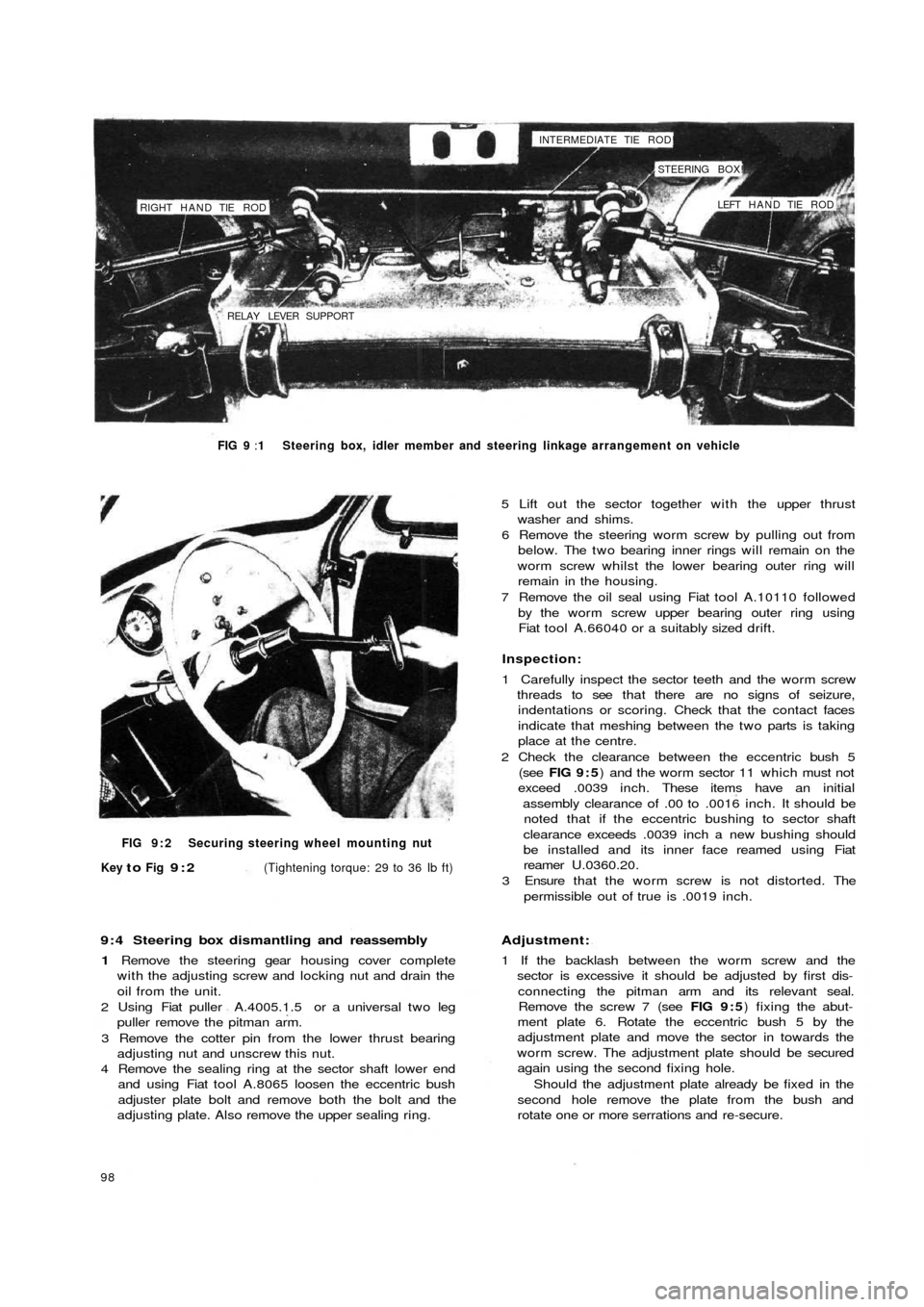
RIGHT HAND TIE ROD
RELAY LEVER SUPPORTINTERMEDIATE TIE ROD!
STEERING BOX!
LEFT HAND TIE ROD
FIG 9 :1 Steering box, idler member and steering linkage arrangement on vehicle
FIG 9 : 2 Securing steering wheel mounting nut
Key
to Fig 9:2(Tightening torque: 29 to 36 Ib ft)
9 : 4 Steering box dismantling and reassembly
1 Remove the steering gear housing cover complete
with the adjusting screw and locking nut and drain the
oil from the unit.
2 Using Fiat puller A.4005.1.5 or a universal t w o leg
puller remove the pitman arm.
3 Remove the cotter pin from the lower thrust bearing
adjusting nut and unscrew this nut.
4 Remove the sealing ring at the sector shaft lower end
and using Fiat tool A.8065 loosen the eccentric bush
adjuster plate bolt and remove both the bolt and the
adjusting plate. Also remove the upper sealing ring.
98
5 Lift out the sector together with the upper thrust
washer and shims.
6 Remove the steering worm screw by pulling out from
below. The two bearing inner rings will remain on the
worm screw whilst the lower bearing outer ring will
remain in the housing.
7 Remove the oil seal using Fiat tool A.10110 followed
by the worm screw upper bearing outer ring using
Fiat tool A.66040 or a suitably sized drift.
Inspection:
1 Carefully inspect the sector teeth and the worm screw
threads to see that there are no signs of seizure,
indentations or scoring. Check that the contact faces
indicate that meshing between the two parts is taking
place at the centre.
2 Check the clearance between the eccentric bush 5
(see FIG 9 : 5) and the worm sector 11 which must not
exceed .0039 inch. These items have an initial
assembly clearance of .00 to .0016 inch. It should be
noted that if the eccentric bushing to sector shaft
clearance exceeds .0039 inch a new bushing should
be installed and its inner face reamed using Fiat
reamer U.0360.20.
3 Ensure that the worm screw is not distorted. The
permissible out of true is .0019 inch.
Adjustment:
1 If the backlash between the worm screw and the
sector is excessive it should be adjusted by first dis-
connecting the pitman arm and its relevant seal.
Remove the screw 7 (see FIG 9 : 5) fixing the abut-
ment plate 6. Rotate the eccentric bush 5 by the
adjustment plate and move the sector in towards the
worm screw. The adjustment plate should be secured
again using the second fixing hole.
Should the adjustment plate already be fixed in the
second hole remove the plate from the bush and
rotate one or more serrations and re-secure.
Page 94 of 128
reassembling and during assembly liberally lubricated
using Fiat W90/M oil (SAE90 EP).
2 The pitman arm nut should be correctly positioned on
reassembly to the sector shaft and both are marked
with notches or a master tooth on the sector will mate
with a double tooth on the pitman arm which will
prevent incorrect reassembly.
3 The pitman arm nut must be tightened to a torque
wrench setting of 72 Ib/ft.
4 Fill the box up to the level and filler plug with SAE90 EP
gear oil.
Refitting the steering box:
To refit the steering box to the vehicle proceed as
follows:
1 Engage the w o r m screw f r o m the steering shaft by
gently manipulating the steering box.
2 Replace the steering box to body nuts and tighten to a
torque wrench setting of 14 to 18 Ib/ft.
3 Replace the t w o track rod pins in their seatings in the
pitman arm and tighten the self-locking nuts to a
torque wrench setting of 18 to 21 Ib/ft.
4 Replace the steering shaft to worm screw mounting
bolt, lock washer and nut.
9 :5 Relay lever and support
The steering idler arm is secured to the body by means
of a support bracket and a rubber bushed pivot bolt. This
is shown in FIG 9 : 7. When this unit is being serviced
the following points should be noted.
1 If there is excessive play between the pin and the
bushes the bushes must be renewed. Also check the
condition of the pin and if there are signs of excessive
wear it must be renewed.
2 To eliminate torsional stresses in the rubber bushes
during assembly the pin nut must be tightened to
torque wrench setting of 39 to 43 Ib/ft, once the
front wheel toe-in has been correctly adjusted w i t h the
wheels set in the straight ahead position.
3 The relay lever support to body mounting nuts must
be tightened to a torque wrench setting of 14 to 18
Ib/ft.
9 : 6 Steering rods (tie rods)
The steering rod is connected to the idler arm and the
drop arm by means of non-adjustable ball joints. The
track rods are connected to the right and left steering
arms by non-adjustable ball joints and comprise t w o
sleeves which are split and having internally threaded
ends. The ball joints are clamped to either end of the
sleeves. To facilitate adjustment one ball joint end has a
lefthand thread and the other a righthand thread.
Adjustment is made by loosening both the clamping bolts
and turning the central sleeve.
To remove the steering rods from the pitman arm, the
relay lever and knuckle arms Fiat pullers A.46006 and
A.6473 or universal ball joint removers should be used.
If excessive play is evident in the ball joint linkage or
the pin is damaged the complete ball joint assembly must
be renewed.
Upon reassembly the tie rod to ball pin knuckle arm
nuts must be tightened to a torque wrench setting of
18 to 21 Ib/ft.
F500101
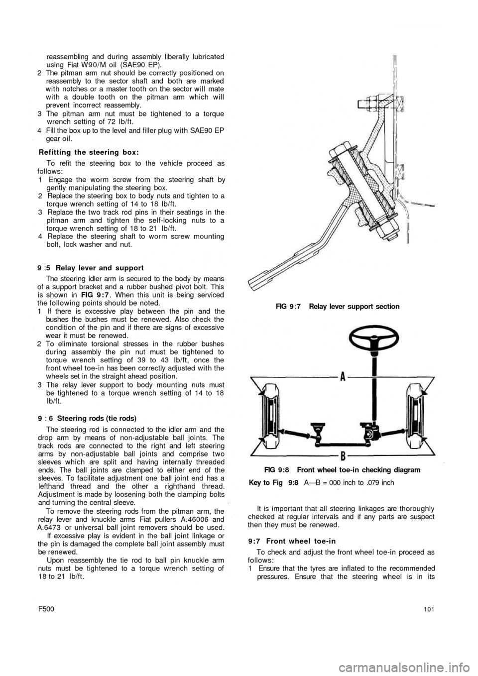
FIG 9:7 Relay lever support section
FIG 9:8 Front wheel toe-in checking diagram
Key to Fig 9:8 A—B = 000 inch to .079 inch
It is important that all steering linkages are thoroughly
checked at regular intervals and if any parts are suspect
then they must be renewed.
9 : 7 Front wheel toe-in
To check and adjust the front wheel toe-in proceed as
follows:
1 Ensure that the tyres are inflated to the recommended
pressures. Ensure that the steering wheel is in its
Page 95 of 128
normal straight-ahead position with the spokes
horizontal. Check that the wheels are in the straight-
ahead position.
2 Load the vehicle to static load conditions or with four
average size passengers.
3 Move the vehicle forwards for a distance of approxi-
mately six yards so that the suspension may settle
correctly.
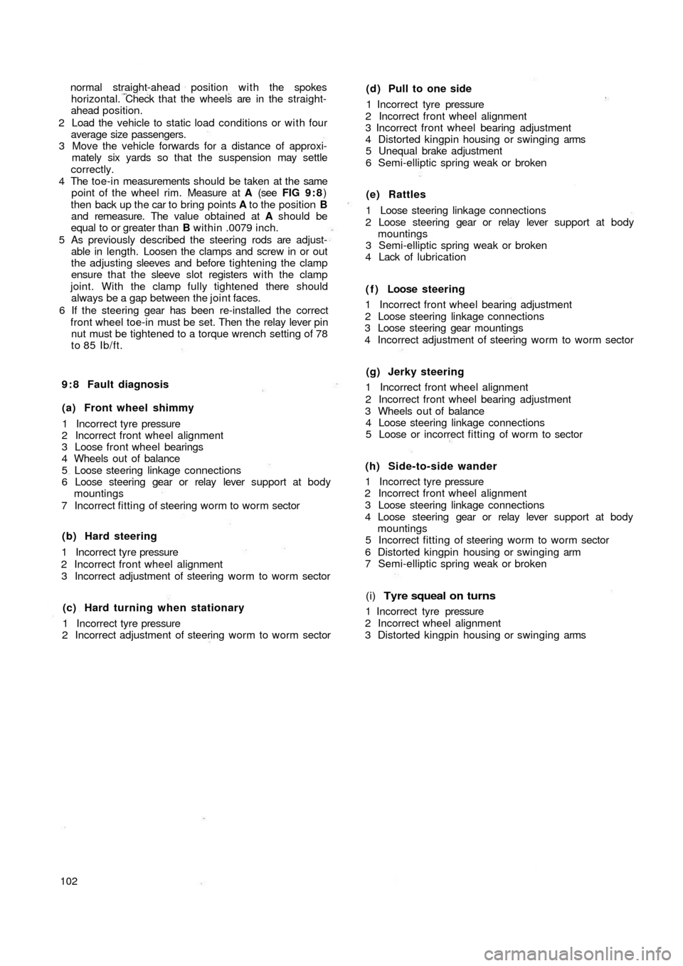
4 The toe-in measurements should be taken at the same
point of the wheel rim. Measure at A (see FIG 9 : 8)
then back up the car to bring points A to the position B
and remeasure. The value obtained at A should be
equal to or greater than B within .0079 inch.
5 As previously described the steering rods are adjust-
able in length. Loosen the clamps and screw in or out
the adjusting sleeves and before tightening the clamp
ensure that the sleeve slot registers w i t h the clamp
joint. With the clamp fully tightened there should
always be a gap between the joint faces.
6 If the steering gear has been re-installed the correct
front wheel toe-in must be set. Then the relay lever pin
nut must be tightened to a torque wrench setting of 78
to 85 Ib/ft.
9 : 8 Fault diagnosis
(a) Front wheel shimmy
1 Incorrect tyre pressure
2 Incorrect front wheel alignment
3 Loose front wheel bearings
4 Wheels out of balance
5 Loose steering linkage connections
6 Loose steering gear or relay lever support at body
mountings
7 Incorrect fitting of steering worm to worm sector
(b) Hard steering
1 Incorrect tyre pressure
2 Incorrect front wheel alignment
3 Incorrect adjustment of steering worm to worm sector
(c) Hard turning when stationary
1 Incorrect tyre pressure
2 Incorrect adjustment of steering worm to worm sector
102
(d) Pull to one side
1 Incorrect tyre pressure
2 Incorrect front wheel alignment
3 Incorrect front wheel bearing adjustment
4 Distorted kingpin housing or swinging arms
5 Unequal brake adjustment
6 Semi-elliptic spring weak or broken
(e) Rattles
1 Loose steering linkage connections
2 Loose steering gear or relay lever support at body
mountings
3 Semi-elliptic spring weak or broken
4 Lack of lubrication
( f ) Loose steering
1 Incorrect front wheel bearing adjustment
2 Loose steering linkage connections
3 Loose steering gear mountings
4 Incorrect adjustment of steering worm to worm sector
(g) Jerky steering
1 Incorrect front wheel alignment
2 Incorrect front wheel bearing adjustment
3 Wheels out of balance
4 Loose steering linkage connections
5 Loose or incorrect fitting of worm to sector
(h) Side-to-side wander
1 Incorrect tyre pressure
2 Incorrect front wheel alignment
3 Loose steering linkage connections
4 Loose steering gear or relay lever support at body
mountings
5 Incorrect fitting of steering worm to worm sector
6 Distorted kingpin housing or swinging arm
7 Semi-elliptic spring weak or broken
(i) Tyre squeal on turns
1 Incorrect tyre pressure
2 Incorrect wheel alignment
3 Distorted kingpin housing or swinging arms
Page 109 of 128
4
53 2 1
7
6
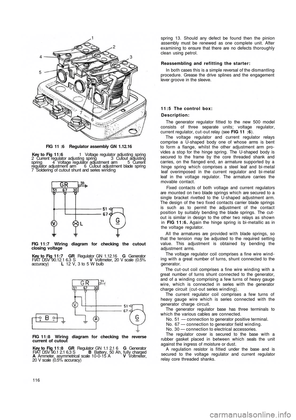
FIG 11 :6 Regulator assembly GN 1.12.16
Key to Fig 11:6 1 Voltage regulator adjusting spring
2 Current regulator adjusting spring 3 Cutout adjusting
spring 4 Voltage regulator adjustment arm 5 Current
regulator adjustment arm 6 Cutout adjustment blade spring
7 Soldering of cutout shunt and series winding
FIG 11:7 Wiring diagram for checking the cutout
closing voltage
Key to Fig 1 1 : 7 GR Regulator GN 1.12.16 G Generator
FIAT DSV 90.12.1 6.3 S V Voltmeter, 20 V scale (0.5%
accuracy) L 12 V, 3 to 5 W bulb
FIG 11:8 Wiring diagram for checking the reverse
current of cutout
Key to Fig 11:8 GR Regulator GN 1.1 2.1 6 G Generator
FIAT DSV 90.1 2.1 6.3 S B Battery, 50 Ah, fully charged
A Ammeter, asymmetrical scale 10-0-15 A V Voltmeter,
20 V scale (0.5% accuracy)
116spring 13. Should any defect be found then the pinion
assembly must be renewed as one complete unit. After
examining to ensure that there are no defects thoroughly
clean using petrol.
Reassembling and refitting the starter:
In both cases this is a simple reversal of the dismantling
procedure. Grease t h e drive splines and the engagement
lever groove in the sleeve.
11:5 The control box:
Description:
The generator regulator fitted to the new 500 model
consists of three separate
units; voltage regulator,
current regulator, cut-out relay (see FIG 11 :6).
The voltage regulator and current regulator relays
comprise a U-shaped body one of whose arms is bent
to form a flange, whilst the other adjustment arm pro-
vides a stop for the hinge spring. The U-shaped body is
secured to the frame by the core threaded shank and
carries, on the flanged end, an armature supported by a
hinge spring which comprises a steel leaf and bi-metal
leaf overimposed in the current regulator and bi-metal
leaf in the voltage regulator. The armature carries the
movable contact.
Fixed contacts of both voltage and current regulators
are mounted on t w o blade springs which are secured to a
single bracket rivetted to the U-shaped adjustment arm.
The design of the t w o fixed contacts carrier blade springs
is such as to permit the adjustment of the contact
position by suitably bending the blade springs. The cut-
out is similar in design to the other two relays as shown
in FIG 11:6. Again the hinge spring is bi-metallic as in
the voltage regulator.
All the armatures are provided w i t h blade springs, so
that the tension may be adjusted to the required setting
value. This adjustment is obtained by bending the
adjustment arms.
The voltage regulator coil comprises a fine wire wind-
ing w i t h a great number of turns, shunt connected to the
generator.
The cut-out coil comprises a fine wire winding with a
great number of turns shunt connected to the generator,
and of a winding comprising a few turns of heavy gauge
wire, which is connected in series w i t h the generator
charge circuit (cut-out series winding).
The current regulator coil comprises a few turns of
heavy gauge wire which is series connected with the
generator charge circuit.
The generator regulator base has three terminals to
which the various cables are connected.
No. 51 — connection to generator positive terminal.
No. 67 — connection to generator field winding.
No. 30 — connection to electrical accessories.
The regulator cover is secured to the base w i t h a
rubber gasket placed in between which seals the unit
against the ingress of moisture or dust.
A regulation resistor is fitted under the base and is
secured to the voltage regulator and current regulator
relay core threaded shanks.
Page 110 of 128
Checking cut-out:
1 Closing voltage:
This test should be carried out at a temperature of
25°±10°C and the regulator should be connected to a
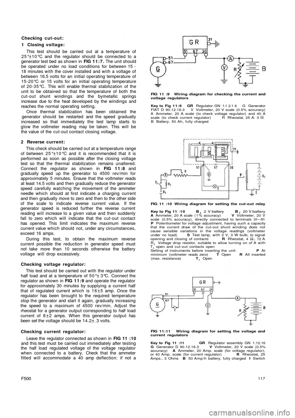
generator test bed as shown in FIG 11:7. The unit should
be operated under no load conditions for between 15 -
18 minutes with the cover installed and w i t h a voltage of
between 16.5 volts for an initial operating temperature of
15-20°C or 15 volts for an initial operating temperature
of 20-35°C. This will enable thermal stabilization of the
unit to be obtained so that the temperature of both the
cut-out shunt windings and the bymetallic springs
increase due to the heat developed by the windings and
reaches the normal operating setting.
Once thermal stabilization has been obtained the
generator should be restarted and the speed gradually
increased so that immediately the test lamp starts to
glow the voltmeter reading may be taken. This will be
the value of the cut-out contact closing voltage.
2 Reverse current:
This check should be carried out at a temperature range
of between 25°±10°C and it is recommended that it is
performed as soon as possible after the closing voltage
test so that the thermal stabilization remains unaltered.
Connect the regulator as shown in FIG 11:8 and
gradually speed up the generator to 4500 rev/min for
approximately 5 minutes. Ensure that the voltmeter reads
at least 14.5 volts and then gradually reduce the generator
speed carefully watching the movement of the ammeter
needle which should at first indicate a charging current
and then gradually move to zero and then to the other side
of the scale to indicate reverse current value. If the
generator speed is reduced further the reverse current
reading will increase to a given value and then suddenly
fall to zero which will indicate that the cut-out contact
has opened. This limit indicates the maximum reverse
current value which should not, under any circumstances,
exceed 16 amps.
During this test, to obtain the maximum reverse
current possible the reduction in generator speed must
not take more than 10 seconds otherwise the battery
voltage will drop excessively.
Checking voltage regulator:
This test should be carried out w i t h the regulator under
half load and at a temperature of 50°± 3°C. Connect the
regulator as shown in FIG 11:9 and operate the regulator
for approximately 30 minutes by supplying a current half
that of regulated current which is 1 6 ±5 amp. Once the
regulator has been brought to the required temperature
stop the generator and start it again, gradually increasing
the speed to a maximum of 4500 rev/min. Adjust the
rheostat for a generator output corresponding to half load
current of 8 ± 2 amps. When this generator output has
been set the voltage should be 14.2± .3 volts.
Checking current regulator:
Leave the regulator connected as shown in
FIG 11 :10
and this test must be carried out immediately after testing
the half load regulated voltage of the voltage regulator
when connected to a battery. Check that the ammeter
fitted will accommodate a 40 amp deflection: if not a
F500117
FIG 11 :9 Wiring diagram for checking the current and
voltage regulators
Key to Fig 11:9 GR Regulator GN 1.1 2.1 6 G Generator
FIAT D 90.12.16.3 V Voltmeter, 20 V scale (0.5% accuracy)
A Ammeter, 20 A scale (to check voltage regulator) and 40 A
scale (to check current regulator)
B Battery, 50 Ah, fully chargedR Rheostat, 25 A. 3
FIG 11 :10 Wiring diagram for setting the cut-out relay
Key to Fig 11 :10 B 2 V battery B 20 V batteryA Ammeter, 20 A scale ( 1 % accuracy) V Voltmeter, 20 V
scale (0.5% accuracy), directly connected to terminals 31—51
P Potentiometer for voltage adjustment, having such a capacity
that the current draw of the cut-out shunt winding does not
cause sensible variations in the voltage readings (voltmeter
under no load) S Test lamp, with 2 V, 3 W bulb, to signal
opening and closing of contacts R Rheostat, 4 12
AR Voltage drop resistor, suitable to allow turning on of A withT open and cut-out contacts open
Setting of instruments before inserting the unit: P At
minimum (voltmeter reads zero) T Open R All inserted
(max. resistance) T Open
FIG 11:11 Wiring diagram for setting the voltage and
current regulators
Key to Fig 11 :11 GR Regulator assembly GN 1.12.16
G Generator D 90.12.16.3 V Voltmeter, 20 V scale (0.5%
accuracy) A Ammeter, 20 Amp. scale (for voltage regulator),
or 40 Amp. scale (for current regulator) R Rheostat, 25
Amps., 3 Ohms B 50 Amp/h battery, fully charged I Switch
Page 111 of 128
Checking cut-out:
1 Closing voltage:
This test should be carried out at a temperature of
25°±10°C and the regulator should be connected to a
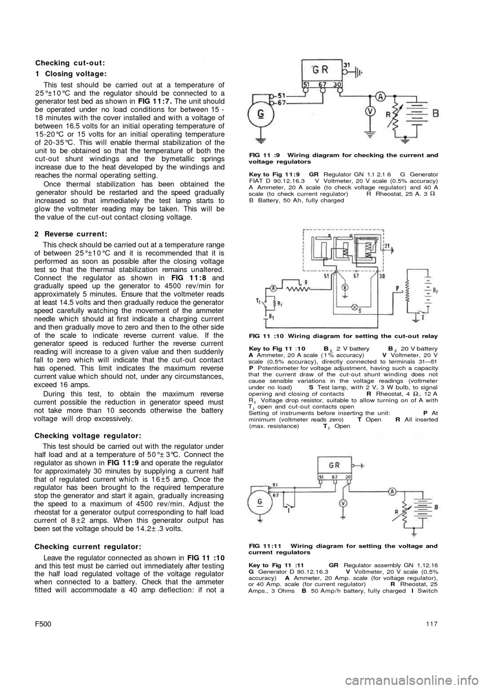
generator test bed as shown in FIG 11:7. The unit should
be operated under no load conditions for between 15 -
18 minutes with the cover installed and w i t h a voltage of
between 16.5 volts for an initial operating temperature of
15-20°C or 15 volts for an initial operating temperature
of 20-35°C. This will enable thermal stabilization of the
unit to be obtained so that the temperature of both the
cut-out shunt windings and the bymetallic springs
increase due to the heat developed by the windings and
reaches the normal operating setting.
Once thermal stabilization has been obtained the
generator should be restarted and the speed gradually
increased so that immediately the test lamp starts to
glow the voltmeter reading may be taken. This will be
the value of the cut-out contact closing voltage.
2 Reverse current:
This check should be carried out at a temperature range
of between 25°±10°C and it is recommended that it is
performed as soon as possible after the closing voltage
test so that the thermal stabilization remains unaltered.
Connect the regulator as shown in FIG 11:8 and
gradually speed up the generator to 4500 rev/min for
approximately 5 minutes. Ensure that the voltmeter reads
at least 14.5 volts and then gradually reduce the generator
speed carefully watching the movement of the ammeter
needle which should at first indicate a charging current
and then gradually move to zero and then to the other side
of the scale to indicate reverse current value. If the
generator speed is reduced further the reverse current
reading will increase to a given value and then suddenly
fall to zero which will indicate that the cut-out contact
has opened. This limit indicates the maximum reverse
current value which should not, under any circumstances,
exceed 16 amps.
During this test, to obtain the maximum reverse
current possible the reduction in generator speed must
not take more than 10 seconds otherwise the battery
voltage will drop excessively.
Checking voltage regulator:
This test should be carried out w i t h the regulator under
half load and at a temperature of 50°± 3°C. Connect the
regulator as shown in FIG 11:9 and operate the regulator
for approximately 30 minutes by supplying a current half
that of regulated current which is 1 6 ±5 amp. Once the
regulator has been brought to the required temperature
stop the generator and start it again, gradually increasing
the speed to a maximum of 4500 rev/min. Adjust the
rheostat for a generator output corresponding to half load
current of 8 ± 2 amps. When this generator output has
been set the voltage should be 14.2± .3 volts.
Checking current regulator:
Leave the regulator connected as shown in
FIG 11 :10
and this test must be carried out immediately after testing
the half load regulated voltage of the voltage regulator
when connected to a battery. Check that the ammeter
fitted will accommodate a 40 amp deflection: if not a
F500117
FIG 11 :9 Wiring diagram for checking the current and
voltage regulators
Key to Fig 11:9 GR Regulator GN 1.1 2.1 6 G Generator
FIAT D 90.12.16.3 V Voltmeter, 20 V scale (0.5% accuracy)
A Ammeter, 20 A scale (to check voltage regulator) and 40 A
scale (to check current regulator)
B Battery, 50 Ah, fully chargedR Rheostat, 25 A. 3
FIG 11 :10 Wiring diagram for setting the cut-out relay
Key to Fig 11 :10 B 2 V battery B 20 V batteryA Ammeter, 20 A scale ( 1 % accuracy) V Voltmeter, 20 V
scale (0.5% accuracy), directly connected to terminals 31—51
P Potentiometer for voltage adjustment, having such a capacity
that the current draw of the cut-out shunt winding does not
cause sensible variations in the voltage readings (voltmeter
under no load) S Test lamp, with 2 V, 3 W bulb, to signal
opening and closing of contacts R Rheostat, 4 12
AR Voltage drop resistor, suitable to allow turning on of A withT open and cut-out contacts open
Setting of instruments before inserting the unit: P At
minimum (voltmeter reads zero) T Open R All inserted
(max. resistance) T Open
FIG 11:11 Wiring diagram for setting the voltage and
current regulators
Key to Fig 11 :11 GR Regulator assembly GN 1.12.16
G Generator D 90.12.16.3 V Voltmeter, 20 V scale (0.5%
accuracy) A Ammeter, 20 Amp. scale (for voltage regulator),
or 40 Amp. scale (for current regulator) R Rheostat, 25
Amps., 3 Ohms B 50 Amp/h battery, fully charged I Switch
Page 112 of 128
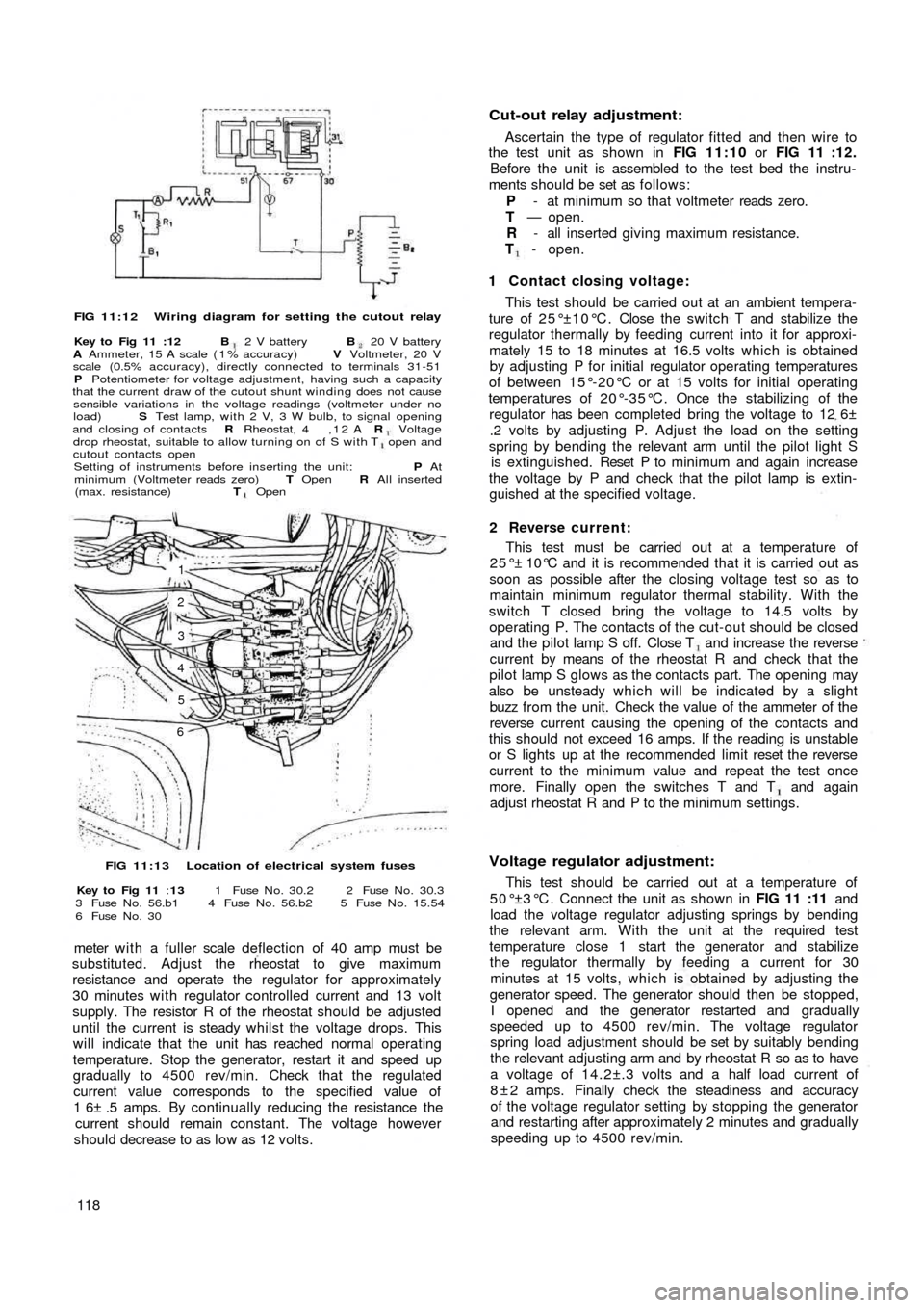
FIG 11:12 Wiring diagram for setting the cutout relay
Key to Fig 11 :12 B 2 V battery B 20 V battery
A Ammeter, 15 A scale ( 1 % accuracy) V Voltmeter, 20 V
scale (0.5% accuracy), directly connected to terminals 31-51
P Potentiometer for voltage adjustment, having such a capacity
that the current draw of the cutout shunt winding does not cause
sensible variations in the voltage readings (voltmeter under no
load) S Test lamp, with 2 V, 3 W bulb, to signal opening
and closing of contacts R Rheostat, 4 , 1 2 A R Voltagedrop rheostat, suitable to allow turning on of S with T open and
cutout contacts open
Setting of instruments before inserting the unit: P At
minimum (Voltmeter reads zero) T Open R All inserted
(max. resistance) T Open
1
2
3
4
5
6
FIG 11:13 Location of electrical system fuses
Key to Fig 11 :13 1 Fuse N o . 30.2 2 Fuse N o . 30.3
3 Fuse N o . 56.b1 4 Fuse N o . 56.b2 5 Fuse N o . 15.54
6 Fuse N o . 30
meter w i t h a fuller scale deflection of 40 amp must be
substituted. Adjust the rheostat to give maximum
resistance and operate the regulator for approximately
30 minutes with regulator controlled current and 13 volt
supply. The resistor R of the rheostat should be adjusted
until the current is steady whilst the voltage drops. This
will indicate that the unit has reached normal operating
temperature. Stop the generator, restart it and speed up
gradually to 4500 rev/min. Check that the regulated
current value corresponds to the specified value of
1 6± .5 amps. By continually reducing the resistance the
current should remain constant. The voltage however
should decrease to as l o w as 12 volts.
118
Cut-out relay adjustment:
Ascertain the type of regulator fitted and then wire to
the test unit as shown in FIG 11:10 or FIG 11 :12.
Before the unit is assembled to the test bed the instru-
ments should be set as follows:
P - at minimum so that voltmeter reads zero.
T — open.
R - all inserted giving maximum resistance.
T - open.
1 Contact closing voltage:
This test should be carried out at an ambient tempera-
ture of 25°±10°C. Close the switch T and stabilize the
regulator thermally by feeding current into it for approxi-
mately 15 to 18 minutes at 16.5 volts which is obtained
by adjusting P for initial regulator operating temperatures
of between 15°-20°C or at 15 volts for initial operating
temperatures of 20°-35°C. Once the stabilizing of the
regulator has been completed bring the voltage to 12 6±
.2 volts by adjusting P. Adjust the load on the setting
spring by bending the relevant arm until the pilot light S
is extinguished. Reset P to m inimum and again increase
the voltage by P and check that the pilot lamp is extin-
guished at the specified voltage.
2 Reverse current:
This test must be carried out at a temperature of
25°± 10°C and it is recommended that it is carried out as
soon as possible after the closing voltage test so as to
maintain minimum regulator thermal stability. With the
switch T closed bring the voltage to 14.5 volts by
operating P. The contacts of the cut-out should be closed
and the pilot lamp S off. Close T and increase the reverse
current by means of the rheostat R and check that the
pilot lamp S glows as the contacts part. The opening may
also be unsteady which will be indicated by a slight
buzz from the unit. Check the value of the ammeter of the
reverse current causing the opening of the contacts and
this should not exceed 16 amps. If the reading is unstable
or S lights up at the recommended limit reset the reverse
current to the minimum value and repeat the test once
more. Finally open the switches T and T and again
adjust rheostat R and P to the minimum settings.
Voltage regulator adjustment:
This test should be carried out at a temperature of
5 0 ° ±3 ° C . Connect the unit as shown in FIG 11 :11 and
load the voltage regulator adjusting springs by bending
the relevant arm. With the unit at the required test
temperature close 1 start the generator and stabilize
the regulator thermally by feeding a current for 30
minutes at 15 volts, which is obtained by adjusting the
generator speed. The generator should then be stopped,
I opened and the generator restarted and gradually
speeded up to 4500 rev/min. The voltage regulator
spring load adjustment should be set by suitably bending
the relevant adjusting arm and by rheostat R so as to have
a voltage of 14.2±.3 volts and a half load current of
8 ± 2 amps. Finally check the steadiness and accuracy
of the voltage regulator setting by stopping the generator
and restarting after approximately 2 minutes and gradually
speeding up to 4500 rev/min.
Page 128 of 128
cushion and back rest. A number of rubber straps are
hooked across the frame under the cushion and in a
sheath covering on the seat back.
The bottom of the front seat frame ends are provided
with sliding guides which run in guide rails attached to
the floor. The sliding guides are pivoted on the frame
tubes to allow for forward tilting of the seats giving better
access to the rear compartment. Two rubber pads
provide cushioning of the seat frame on the guide rails
as shown in FIG 12:11. The control lever for seat
adjustment is fitted in the frame righthand tube to permit
unlocking of the seats so that they may be adjusted to
individual drivers requirements.
Rear seats (Sedan):
The rear seat comprises of a foam rubber cushion and
back. The seat back is cemented to the rear floor and
body shell bulkhead. The rear seat lining is of fabric and
imitation leather. The seat lining is held in place by four
self-tapping screws, t w o of which secure the floor below
the back window and two the lining at the base of t h e
back rest. Included with the seat assembly is a masonite
floor which is fitted below the rear window.
Rear Seat (Station Wagon):
The rear seat back rest is pivoted at the base of its
frame so that it can be folded down to form a load plat-
form surface. In the upright position it is retained in place
by t w o brackets mounted on either side of the body below
the side
windows.
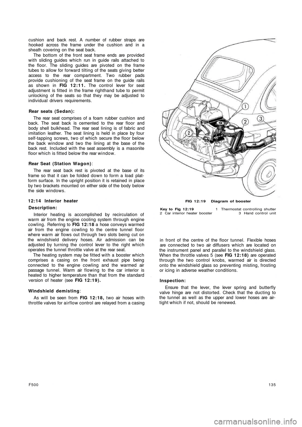
12:14 Interior heater
Description:
Interior heating is accomplished by recirculation of
warm air from the engine cooling system through engine
cowling. Referring to FIG 12:18 a hose conveys warmed
air from the engine cowling to the centre tunnel floor
where warm air flows out through two slots being cut on
the windshield delivery hoses. Air admission can be
adjusted by turning the control lever to the right which
operates the tunnel throttle valve at the rear seat.
The heating system may be fitted with a booster which
comprises a casing on the front exhaust pipe being
connected to the engine cowling and the warmed air
passage tunnel. Warm air flowing to the car interior is
heated to higher temperature than that from the standard
version of heater (see FIG 12:19).
Windshield demisting:
As will be seen from FIG 12:18, t w o air hoses w i t h
throttle valves for airflow control are relayed from a casing
F500135
FIG 12:19 Diagram of booster
Key to Fig 12:19 1 Thermostat controlling shutter
2 Car interior heater booster 3 Hand control unit
in front of the centre of the floor tunnel. Flexible hoses
are connected to two air diffusers which are located on
the instrument panel and parallel to the windshield glass.
When the throttle valves 5 (see FIG 12:18) are operated
through the two control knobs, warmed air is directed
onto the windshield glass so preventing misting, frosting
or icing in adverse weather conditions.
Inspection:
Ensure that t h e lever, the lever spring and butterfly
valve hinge are not distorted. Check that the ducting to
the tunnel as well as the upper and lower hoses are air-
tight which if not, should be renewed.