low oil pressure FIAT 500 1964 1.G User Guide
[x] Cancel search | Manufacturer: FIAT, Model Year: 1964, Model line: 500, Model: FIAT 500 1964 1.GPages: 128, PDF Size: 9.01 MB
Page 26 of 128
4 Mixture too weak
5 Water in fuel system
6 Petrol tank vent blocked
7 Incorrect valve clearance
(c) Engine idles badly
1 Check 1 and 6 in (b)
2 Air leak at manifold joints
3 Slow-running jet blocked or out of adjustment
4 Air leak in carburetter
5 Over-rich mixture
6 Worn piston rings
7 Worn valve stems or guides
8 Weak exhaust valve springs
(d) Engine misfires
1 Check 1, 2, 3, 4, 5, 8, 10, 13, 14, 1 5, 16, 17 in (a);
2, 3, 4 and 7 in (b)
2 Weak or broken valve springs
(e) Engine overheats
1 Generator and fan drive belt too loose
2 Shutter or thermostat seized in closed position
(f) Compression low
1 Check 14 and 15 in (a), 6 and 7 in (c) and 2 in (d)
2 Worn piston ring grooves
3 Scored or worn cylinder bores
(g) Engine lacks power
1 Check 3, 10, 1 1 , 13, 14, 15, 16 and 17 in (a), 2, 3, 4
and 7 in (b) 6 and 7 in (c) and 2 in (d). Also check (e)
and (f)
2 Leaking joint washers
3 Fouled sparking plugs
4 Automatic centrifugal advance not operating
(h) Burnt valves or seats
1 Check 14 and 15 in (a), 7 in (b) and 2 in (d). Alsocheck (e)
2 Excessive carbon around valve seat and head
(j) Sticking valves
1 Check 2 in (d)
2 Bent valve stem
3 Scored valve stem or guide
4 Incorrect valve clearance
(k) Excessive cylinder wear
1 Check 11 in (a) and see Chapter 4
2 Lack of oil
3 Dirty oil
4 Piston rings gummed up or broken
5 Badly fitting piston rings
6 Connecting rods bent
(l) Excessive oil consumption
1 Check 6 and 7 in (c) and check (k)
2 Ring gaps too wide
3 Oil return holes in piston choked with carbon
4 Scored cylinders
5 Oil level too high
6 External oil leaks
7 Ineffective valve stem oil seals
(m) Crankshaft and connecting rod bearing failure
1 Check 2 in (k)
2 Restricted oilways
3 Worn journals or crank pins
4 Loose bearing caps
5 Extremely low oil pressure
6 Bent connecting rod
(n) High fuel consumption (see Chapter 2)
(o) Engine vibration
1 Loose generator bolts
2 Blower blade assembly out-of-balance
3 Incorrect clearance for rear engine mounting rubber
F50033
Page 41 of 128
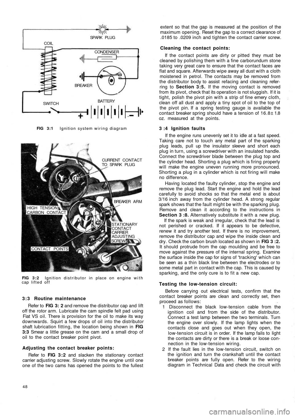
FIG 3 : 1 Ignition system wiring diagram
BATTERY
SWITCHBREAKER COIL
SPARK PLUG
CONDENSER
FIG 3 : 2 Ignition distributor in place on engine with
cap lifted offCURRENT CONTACT
TO SPARK PLUG
BREAKER A R M
STATIONARY
CONTACT
CARRIER
ADJUSTING
SCREW
CONTACT POINTS HIGH TENSION)
CARBON CONTACT
3 : 3 Routine maintenance
Refer to FIG 3: 2 and remove the distributor cap and lift
off the rotor arm. Lubricate the cam spindle felt pad using
Fiat VS oil. There is provision for the oil to make its way
downwards. Squirt a few drops of oil into the distributor
shaft lubrication fitting, the location being shown in FIG
3:3 Smear a little grease on the cam and a small drop of
oil to the contact breaker point pivot.
Adjusting the contact breaker points:
Refer to FIG 3 : 2 and slacken the stationary contact
carrier adjusting screw. Slowly rotate the engine until one
one of the t w o cams has opened the points to the fullest
48
extent so that the gap is measured at the position of the
maximum opening. Reset the gap to a correct clearance of
.0185 to .0209 inch and tighten the contact carrier screw.
Cleaning the contact points:
If the contact points are dirty or pitted they must be
cleaned by polishing them with a fine carborundum stone
taking very great care to ensure that the contact faces are
flat and square. Afterwards wipe away all dust with a cloth
moistened in petrol. The contacts may be removed from
the distributor body to assist refacing and cleaning refer-
ring to Section 3:5. If the moving contact is removed
from its pivot, check that its operation is not sluggish. If it is
tight, polish the pivot pin with a strip of fine emery cloth,
clean off all dust and apply a tiny spot of oil to the top of
the pivot pin. If a spring testing gauge is available the
contact breaker spring should have a tension of 16.8± 1.8
oz. measured at the points.
3 :4 Ignition faults
If the engine runs unevenly set it to idle at a fast speed.
Taking care not to touch any metal part of the sparking
plug leads, pull up the insulator sleeve and short each
plug in turn, using a screwdriver with an insulated handle.
Connect the screwdriver blade between the plug top and
the cylinder head. Shorting a plug which is firing properly
will make the engine uneven running more pronounced.
Shorting a plug in a cylinder which is not firing will make
no difference.
Having located the
faulty cylinder, stop the engine and
remove the plug lead. Start the engine and hold the lead
carefully to avoid shocks so that the metal end is about
3/16 inch away from the cylinder head. A strong regular
spark shows that the fault might be with the sparking plug.
Remove and clean it according to the instructions in
Section 3 :8. Alternatively substitute it with a new plug.
If the spark is weak and irregular, check that the lead is
not perished or cracked. If it appears to be defective,
renew it and try another test. If there is no improvement,
remove the distributor cap and wipe the inside clean and
dry. Check the carbon brush located as shown in FIG 3 : 2 .
It should protrude from the cap moulding and be free to
move against the pressure of the internal spring. Examine
the surface inside the cap for signs of 'tracking' which can
be seen as a thin black line between the electrodes or to
some metal part in contact with the cap. This is caused by
sparking, and the only cure is to fit a new cap.
Testing the low-tension circuit:
Before carrying out electrical tests, confirm that the
contact breaker points are clean and correctly set, then
proceed as follows:
1 Disconnect the black low-tension cable from the
ignition coil and from the side of the distributor.
Connect a test lamp between the t w o terminals. Turn
the engine over slowly. If the lamp lights when the
contacts close and goes out when they open, the
low-tension circuit is in order. If the lamp fails to light
the contacts are dirty or there is a break or loose con-
nection in the low-tension wiring.
2 If the fault lies in the
low-tension circuit, switch on
the ignition and turn the crankshaft until the contact
breaker points are fully open. Refer to the wiring
diagram in Technical Data and check the circuit with
Page 44 of 128
indicates the condition inside the combustion chamber
and may be used as a guide to engine tuning.
Before the spark plugs are removed b l o w away any
loose dirt from the plug recesses using a compressed air
jet or tyre pump. Store the plugs in the order of removal
ready for inspection.
Examine the gaskets and if they are about half their
thickness they may be used again otherwise they must be
replaced.
Inspect the electrode end of the plugs and note the
type and colour of the deposit. Normally it should be
powdery and range from b r o w n to a greyish tan in colour.
There will also be slight wear of the electrodes and the
general effect described is one which comes from mixed
periods of high-speed and low-speed driving. Cleaning
and resetting the gap is all that will be necessary.
If the deposits are white or yellowish they indicate long
periods of constant-speed driving or much low-speed
city driving. Again, the treatment is straightforward.
Dry, black, fluffy deposits are usually the result of
running with too rich a mixture. Incomplete combustion
of the petrol air charge may also be a cause and this might
be traced to a defect in the ignition system or excessive
idling.
Overheated sparking plugs have a white blistered look
about the centre electrode and the side electrode may be
badly eroded. This may be caused by poor cooling, wrong
ignition timing or sustained high speeds under heavy load.
To clean the sparking plugs effectively they should be
cleaned using an abrasive blasting machine and tested
under pressure once the electrodes have been reset. File
these until they are clean, bright and the faces parallel and
set the gap to .019 to .023 inch. Do not try to bend the
centre electrode.
Before replacing the plugs use a wire brush to clean the
threads taking care that the electrodes are not touched.
Thoroughly clean the spark plug in petrol, and dry using a
compressed air jet or a tyre pump. If difficulty is found in
screwing the plugs into the cylinder head by hand run a
tap d o w n the threads to clear away any carbon. If a tap is
not available use an old sparking plug with crosscuts d o w nthe threads. Finally tighten the plugs to a torque wrench
setting of 18 to 21 Ib ft.
Sparking plug leads:
The spark plug leads and the lead from the coil to the
distributor cap must be regularly checked for cracking of
the insulation and also correct seating in the distributor
cap and coil top. It is recommended that silicone grease is
smeared around the sockets before the leads are replaced
to ensure no moisture may enter causing difficult starting.
3 : 9 The distributor driving spindle (sedan and
sports engine)
If for any reason, the driving spindle has been removed
from its housing in the crankcase, it must be correctly
meshed w i t h the camshaft gear otherwise it
will be impos-
sible to set the ignition timing.
3:10 Fault diagnosis
(a) Engine w i l l not fire
1 Battery discharged
2 Distributor contact points dirty, pitted or maladjusted
3 Distributor cap dirty, cracked or tracking
4 Carbon brush inside distributor cap not touching rotor
5 Faulty cable or loose connection in low-tension circuit
6 Distributor rotor arm cracked
7 Faulty coil
8 Broken contact breaker spring
9 Contact points stuck open
(b) Engine misfires
1 Check 2, 3, 4, and 7 in (a)
2 Weak contact breaker spring
3 High-tension plug and coil leads cracked or perished
4 Sparking plug(s) loose
5 Sparking plug insulation cracked
6 Sparking plug gap incorrectly set
7 Ignition timing too far advanced
Page 52 of 128
CHAPTER 5
THE CLUTCH
5:1
5:2
5:3
5:4Description
Removal and installation
Dismantling and inspection of clutch cover
Assembly and adjustment
5:1 Description
New 500, 500D sedan and early station wagon:
The clutch is a single plate dry disc type operating on
the inner face of the flywheel. FIG 5 :1 shows a longitudi-
nal cross section of the clutch as it is assembled in the
power unit.
A sheet metal clutch cover is attached to the flywheel
by means of six screws and this encloses a clutch driven
plate, the pressure plate and six springs. Three withdrawal
levers are fitted so that the inner ends are attached to a
carrier ring through which three springs hold the levers in
place and the carrier ring in contact with the pressure plate,
(see FIG 5 : 1) . Release of the driven plate is obtained
through a throw-out ring fitted with a central carbon
thrust ring which acts on the withdrawal levers carrier
ring. This is controlled by the clutch pedal through suitable
linkage to the control fork.
When the clutch pedal is operated, the throw-out ring,
together with the carbon thrust ring is pushed towards the
flywheel and this exerts a pressure on the w i t h d rawal
levers carrier ring and the lever inner tips. The lever outer
tips lift the pressure plate so disengaging the clutch.
F50059
Each of the three withdrawal levers is mounted on a bolt
together with an adjustment nut which is inserted in the
pressure plate. The levers are kept in their location by a
guide which is formed in the pressure plate.
500 F and L sedans and late station wagon:
A single plate dry type clutch is fitted with a diaphragm
pressure spring. This design of clutch differs from the con-
ventional clutch because the pressure coil springs and
throw-out mechanism components are replaced by a
single diaphragm spring.
The new system offers certain advantages which are as
follows:
1 The load on the clutch pedal does not increase as the
clutch disc lining wears but remains constant through-
out the life of the clutch.
2 Due to the special shape and location of the diaphragm
spring, which offers a constant force on the pressure
plate throughout the clutch life, the clutch does not slip
even though the driven plate linings may be worn. 5:5
5:6
5:7
5:8Installation of clutch on flywheel
Pilot bushing
Withdrawal mechanism
Fault diagnosis
Page 56 of 128
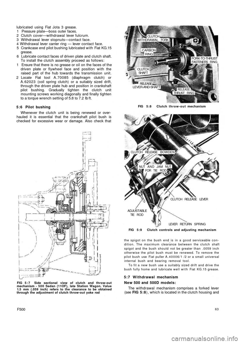
lubricated using Fiat Jota 3 grease.
1 Pressure plate—boss outer faces.
2 Clutch cover—withdrawal lever fulcrum.
3 Withdrawal lever stopnuts—contact face.
4 Withdrawal lever carrier ring — lever contact face.
5 Crankcase end pilot bushing lubricated with Fiat KG.15
grease.
6 Lubricate contact faces of driven plate and clutch shaft.
To install the clutch assembly proceed as follows:
1 Ensure t h a t there is no grease or oil on the faces of the
driven plate or flywheel face and position with the
raised part of the hub towards the transmission unit.
2 Locate Fiat tool A.70085 (diaphragm clutch) or
A . 6 2 0 2 3 (coil spring clutch) or a suitably sized drift,
through the driven plate hub and position in crankshaft
pilot bushing. Gradually tighten the clutch unit
mounting screws working diagonally and finally tighten
to a torque wrench setting of 5.8 to 7.2 Ib ft.
5 : 6 Pilot bushing
Whenever the clutch unit is being renewed or over-
hauled it is essential that the crankshaft pilot bush is
checked for excessive wear or damage. Also check that
FIG 5 : 7 Side sectional view of clutch and throw-out
mechanism - 5 0 0 Sedan (11OF), late Station Wagon. Value
1.5 mm (.059 inch) refers to the clearance to be obtained
through the adjustment of clutch throw-out yoke rod
F50063
The withdrawal mechanism comprises a forked lever
(see FIG 5 : 8), which is located in the clutch housing and 5:7 Withdrawal mechanism
New 500 and 500D models:
the spigot on the bush end is in a good serviceable con-
dition. The maximum clearance between the clutch shaft
spigot and the bush should not be greater than .0059 inch
otherwise the pilot bush must be renewed. To remove the
pilot bush use Fiat puller A.40006/1 /2 or a small universal
internal bush and bearing removal tool.
To fit a new bush use a suitably sized drift and drive the
bush fully home and lubricate well with Fiat KG.15 grease. FIG 5 : 9 Clutch controls and adjusting mechanism LEVER RETURN SPRING
ADJUSTABLETIE R O DCLUTCH RELEASE LEVER NUT A N D JAM NUT
FOR TIE R O D CLUTCH RELEASE BOWDEN FIG 5:8 Clutch throw-out mechanism
CLUTCHSHAFT
LEVER-AND-SHAFT
RELEASE
RELEASETHRUST RING
FORK-TO-THRUSTFASTENERS RING
CARBON
RING
WITHDRAWAL FORKCLUTCH
Page 79 of 128
A tolerance of —10'.+ 15' is permitted providing
that the value is the same for both rear wheels. It is
important that both rear wheels are set to the same
angle otherwise uneven tyre wear and adverse handl-
ing conditions will result. When the wheel is parallel to
the centre line of the vehicle the pin of bracket
C.696/3 will be .216 inch apart from the pin of the
front suspension swinging arm.
7 Release the swinging arm outer support to body
mounting screws and position arm in such a way as to
obtain the condition as described in Number 6 above.
After the adjustment has been completed tighten
the outer support mounting screws to a torque wrench
setting of 28.9 to 36.2 Ib/ft. Also tighten the two
swinging arm pin nuts C (see FIG 7 : 7) to a torque
wrench setting of 43.4 to 50.6 Ib/ft. Take off the gauge
C.696 w i t h bracket and support C.696/3, and repeat
the check and adjustment operations on the other
wheel. Care must be taken to ensure that bracket
C.696/3 is reversed from the position previously used.
New 500 type 500D, 110F and 110L sedan and
station wagon:
After the rear suspension has been replaced, check
and, if necessary adjust the rear wheel geometry.
1 Inflate the tyres to the normal operating pressures.
2 Lower the car body so that the rear wheels are set at
90 deg. to the floor. This condition is obtained when
the lowermost portion of the sump is 6.61 inches from
the floor level for the new 500D model or the centre
rear bracket for jacking up the rear of t h e vehicle
8.9 inches from the floor level for the 500 Station
Wagon.
3 With the vehicle set to the above conditions check the
wheel geometry. The wheel plane must converge w i t h
the centre line of the vehicle by an angle of 0 deg. 10'
(—10', +15') toeing in at the front.
4 The wheel plane must be 22.343 ± .059 inches from
the centre line of the vehicle for the 500D model.
Whereas for the 500 Station Wagon the distance must
be 22.264 ± .059 inches.
5 To adjust the rear wheel toe-in adjust the positions of
the mounting screws A and B as shown in FIG 7:7.
86
7:7 Modifications
The new 500 Sedan (110F) and late 500 Station
Wagon are fitted with modified wheels side flexible
joints and rear control arm as shown in FIG 7:13.
Together w i t h these modifications a new design rear
coil spring has been fitted details of which are given in
Technical Data.
7 : 8 Fault diagnosis
(a) Irregular or abnormal tyre wear
1 Incorrect tyre pressure
2 Wheels out of balance
3 Wheels off centre
4 Misadjusted brakes
5 Weak or broken coil springs
6 Excessive load
7 Incorrect wheel alignment
(b) Sag on one wheel
1 Incorrect tyre pressure
2 Weak or broken coil spring
3 Wear of shock absorber causing poor dampening
action
(c) Squeaks, thumps or rattles
1 Wheels out of balance
2 Wheels off centre
3 Misadjusted brakes
4 Weak or broken coil springs or spring seats dislodged
5 Wear of shock absorbers causing poor dampening
action
6 Worn rubber bushings in control arms
7 Poor lubrication of wheel bearings
(d) Pull to one side
1 Incorrect tyre pressure
2 Misadjusted brakes
3 Distorted suspension arm
Page 86 of 128
8 : 7 Hydraulic damper:
Description:
The front and rear shock absorbers are of the telescopic
double acting type. Their dampening action takes place
directly on the suspension without the use of any
intermediate linkage. The shock absorber comprises a
cylindrical body formed by to coaxial tubes 14 and 15
(see FIG 8:11), the inner tube acting as the working
cylinder and the outer one as a casing. The fluid reservoir
being located between the two sections. A third outer
cylinder 13 shields the rod 2 from any road dirt.
On the top the cylinder body is enclosed by a bush 1 1 ,
oil seals 5 and 9 and a housing 4. The rod 2 slides through
the seals 5, the upper end is fixed into the vehicle body
floor and its lower end carries the piston 22 on which
rebound 26 and inlet valves 21 are arranged.
The bottom of the shock absorber is closed by a plug
35 with a threaded shank 36 for the shock absorber to be
mounted onto the suspension unit. The cylinder 15 and
carrier plug 32 is mounted with a compensation valve
30 and a compression valve 33. The piston is provided
with two rows of orifices. The internal row is blanked
underneath by the rebound valve which operates
downwards. The external row is blanked by the inlet
valve which opens upwards. Hydraulic shock absorbers
fitted since March 1959 are provided w i t h a vapour
pocket bleeder from the cylinder exterior. The bleeder
device comprises a capillary
hole 12 interconnecting the
inner cylinder 15 with the upper chamber 10 and also a
passage tube 16 from the upper chamber to the fluid
reservoir. Any vapour pockets in the pressure cylinder
are excluded past the capillary hole 12 into the chamber
10 from which they flow downwards during shock
absorber operation through the passage 16 in a light
fluid stream and up to the top of the reservoir with the
reservoir fluid.
Dismantling and inspection:
Normally during service if a shock absorber becomes
weak in operation then a new unit should be fitted.
Should however, it be necessary for the original unit to
be overhauled proceed as follows:
1 Thoroughly clean the outer casing in petrol and blow
dry using a compressed air jet.
2 Firmly clamp the lower shank of the shock absorber
in a vice and telescope upwards the outer casing and
using Fiat wrench A.56024 unscrew the upper
threaded ring 3 (see FIG 8:11).
3 Remove the shock absorber from the vice and carefully
remove the inner cylinder 15 using a screwdriver
inserted in the cylinder bottom chamfer and remove
the lower plug 32 which carries the compression and
compensation valves.
4 Push the rod i n t o the cylinder 15 and clamp the upper
shank in a vice. Unscrew the plug 29, and carefully
remove the piston 22 together with the inlet and
rebound valves. Withdraw the rod 2 from the cylinder
15 and remove the seal gasket, the housing, and
threaded ring. Thoroughly wash all parts in petrol and
carefully blow dry using a c
ompressed air jet. The
following parts should be inspected as follows.
Check that the inlet, rebound and compensation valve
discs are not deformed or show signs of cracking.
F50093 Inspect the surfaces of the piston, the seal ring and the
compression valve to ensure that they are smooth and
hydraulic fluid tight. Check that the rebound and
compression valve springs and upper seal gasket
springs are not broken or weak. Carefully inspect the
t w o seal gaskets for damage or wear and it is recom-
mended that they are renewed upon reassembly.
Check that the rod and the cylinders show no sign of
deformation and that the air pocket evacuating
passage is not blocked. Also check that the capillary
hole 12 is not blocked. Any parts which show signs
of wear or damage must be renewed.
Reassembly:
Reassembly of the shock absorber is the reverse
procedure to dismantling. Special care must be taken
when refilling the shock absorber w i t h Fiat SA1 oil
otherwise its operating characteristics will be altered.
The hydraulic fluid capacity for the front shock
absorbers is .112 imperial quarts.
The hydraulic capacity for the rear shock absorbers is
.088 imperial quarts. Only Fiat—SA1 oil must be
used.
To insert the components into the shock absorber
body proceed as follows:
1 Mount the piston on the rod, and insert the piston and
rod assembly into the cylinder 15 (see FIG 8:11).
2 Push the piston against the bush 11 and then very
carefully pour the correct amount of hydraulic fluid
up to about j inch from the edge.
3 Press f i t t h e plug 32 and pour the remaining fluid into
the casing 14.
4 Insert the cylinder 15 into the casing 14 and tighten
the upper threaded ring 3.
8 :8 Front suspension assembly and installation
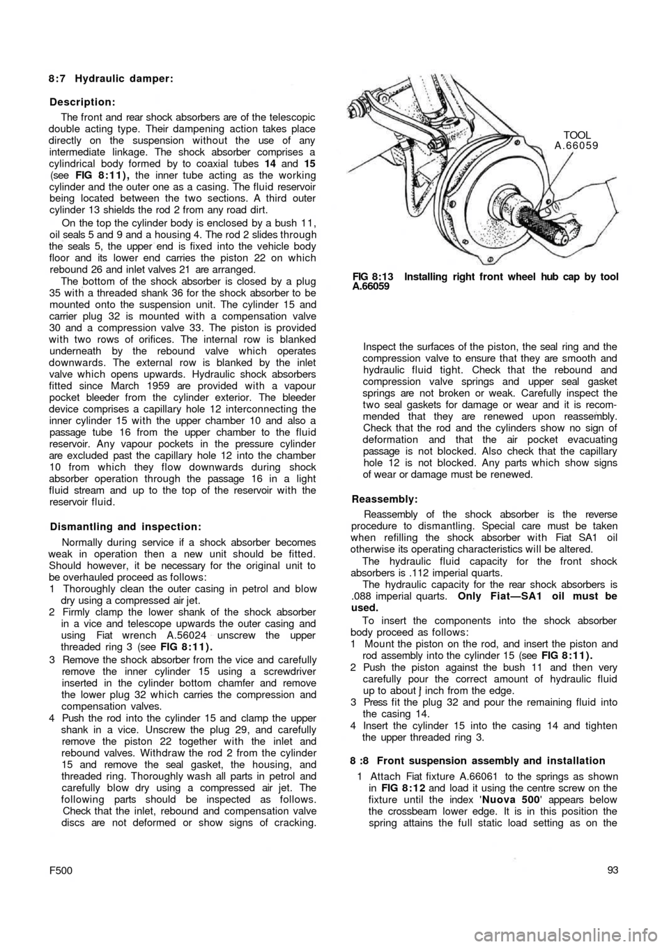
1 Attach Fiat fixture A.66061 to the springs as shown
in FIG 8:12 and load it using the centre screw on the
fixture until the index 'Nuova 500' appears below
the crossbeam lower edge. It is in this position the
spring attains the full static load setting as on the FIG 8:13 Installing right front wheel hub cap by tool
A.66059TOOL
A.66059
Page 94 of 128
reassembling and during assembly liberally lubricated
using Fiat W90/M oil (SAE90 EP).
2 The pitman arm nut should be correctly positioned on
reassembly to the sector shaft and both are marked
with notches or a master tooth on the sector will mate
with a double tooth on the pitman arm which will
prevent incorrect reassembly.
3 The pitman arm nut must be tightened to a torque
wrench setting of 72 Ib/ft.
4 Fill the box up to the level and filler plug with SAE90 EP
gear oil.
Refitting the steering box:
To refit the steering box to the vehicle proceed as
follows:
1 Engage the w o r m screw f r o m the steering shaft by
gently manipulating the steering box.
2 Replace the steering box to body nuts and tighten to a
torque wrench setting of 14 to 18 Ib/ft.
3 Replace the t w o track rod pins in their seatings in the
pitman arm and tighten the self-locking nuts to a
torque wrench setting of 18 to 21 Ib/ft.
4 Replace the steering shaft to worm screw mounting
bolt, lock washer and nut.
9 :5 Relay lever and support
The steering idler arm is secured to the body by means
of a support bracket and a rubber bushed pivot bolt. This
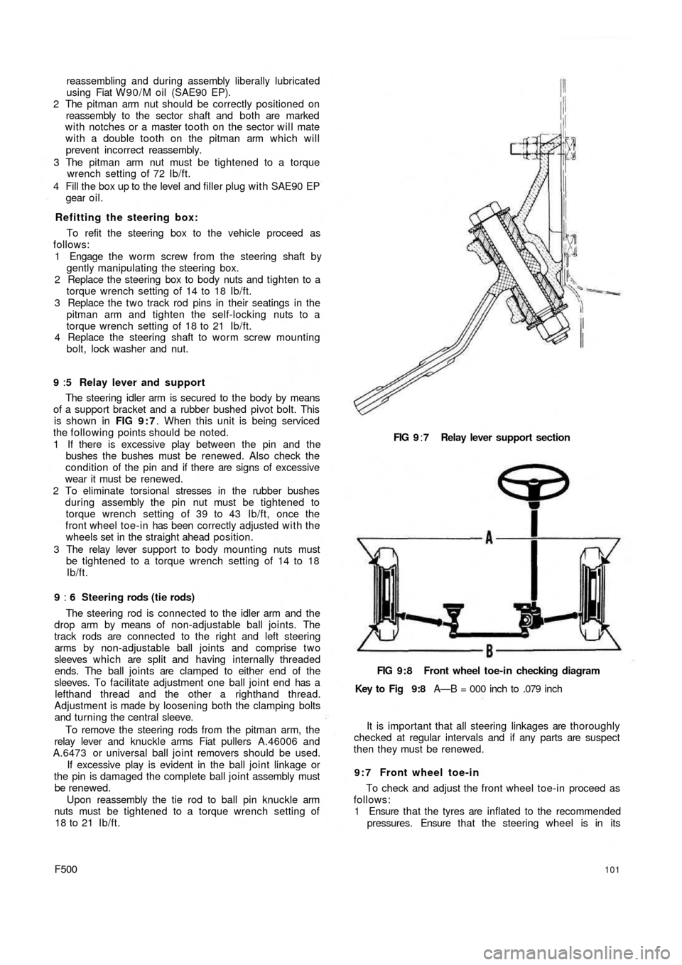
is shown in FIG 9 : 7. When this unit is being serviced
the following points should be noted.
1 If there is excessive play between the pin and the
bushes the bushes must be renewed. Also check the
condition of the pin and if there are signs of excessive
wear it must be renewed.
2 To eliminate torsional stresses in the rubber bushes
during assembly the pin nut must be tightened to
torque wrench setting of 39 to 43 Ib/ft, once the
front wheel toe-in has been correctly adjusted w i t h the
wheels set in the straight ahead position.
3 The relay lever support to body mounting nuts must
be tightened to a torque wrench setting of 14 to 18
Ib/ft.
9 : 6 Steering rods (tie rods)
The steering rod is connected to the idler arm and the
drop arm by means of non-adjustable ball joints. The
track rods are connected to the right and left steering
arms by non-adjustable ball joints and comprise t w o
sleeves which are split and having internally threaded
ends. The ball joints are clamped to either end of the
sleeves. To facilitate adjustment one ball joint end has a
lefthand thread and the other a righthand thread.
Adjustment is made by loosening both the clamping bolts
and turning the central sleeve.
To remove the steering rods from the pitman arm, the
relay lever and knuckle arms Fiat pullers A.46006 and
A.6473 or universal ball joint removers should be used.
If excessive play is evident in the ball joint linkage or
the pin is damaged the complete ball joint assembly must
be renewed.
Upon reassembly the tie rod to ball pin knuckle arm
nuts must be tightened to a torque wrench setting of
18 to 21 Ib/ft.
F500101
FIG 9:7 Relay lever support section
FIG 9:8 Front wheel toe-in checking diagram
Key to Fig 9:8 A—B = 000 inch to .079 inch
It is important that all steering linkages are thoroughly
checked at regular intervals and if any parts are suspect
then they must be renewed.
9 : 7 Front wheel toe-in
To check and adjust the front wheel toe-in proceed as
follows:
1 Ensure that the tyres are inflated to the recommended
pressures. Ensure that the steering wheel is in its
Page 98 of 128
2 Using Fiat puller A.46023 as shown in FIG 8 : 9
remove the wheel grease cap.
3 Using a universal t w o leg puller or Fiat puller A.40005
together w i t h items 1 and 9 remove the wheel hub/
drum assembly having first extracted the splitpin if
fitted and released the hub retaining nut (see FIG
8:10).
Dismantling brake unit:
1 Using a compressed air jet thoroughly clean all com-
ponents of the brake assembly.
2 Make a note of the location of the shoe return springs
and gently ease the shoes away from the brake
backplate (see FIG 10:2).
3 Disconnect the hydraulic line from the rear of t h e
wheel cylinder and remove the t w o cylinder retaining
bolts. Lift away the hydraulic cylinder.
Brake shoe lining:
Check the lining thickness and if found to be exces-
sively reduced service replacement shoes must be fitted.
The minimum allowable brake lining thickness is .059
inch.
Thoroughly check the linings for signs of oil or grease
which, if evident, the shoes must be renewed and the
drums and oil seals thoroughly inspected for the cause
of oil ingress and the cause remedied before reassembly.
Do not fit odd brake shoes and do not mix materials or
unbalanced braking will result.
Do not allow grease, oil or paint to contact the friction
linings.
Brake drums:
Whilst servicing the brakes, thoroughly inspect the
drums for scoring, ovality or distortion as well as inspect-
ing for minute hair line cracks. The drums may be refaced
by using a centre lathe and finally finishing by lapping
the drums to smooth out possible tool marks. The
maximum permissible oversize beyond the nominal drum
diameter of 6.702 to 6.712 inch is .039 inch. This limit
must never be exceeded otherwise the strength of the
drum will be impaired or a reduction in braking efficiency
caused by the increase of shoe expansion travel and the
consequent diminished contact pressure.
No brake adjustment will be required on the new 500
Saloon models after the drum has been reassembled as
the self-adjusting device will accommodate for the shoe
position to the new drum diameter during the first
operation of the brake pedal.
Reassembly of front brakes:
This is the reverse procedure to dismantling. Ensure
that the pull-off springs are correctly fitted to the holes in
the webs of the brake shoes and that the shoes register
correctly in the slotted ends of the pistons and the
side
mounting plate.
Upon assembly of the hub and brake drum assembly
liberally pack the space between the two bearings w i t h
Fiat MR grease, and remount the hub according to the
instructions in Chapter 8.
F500
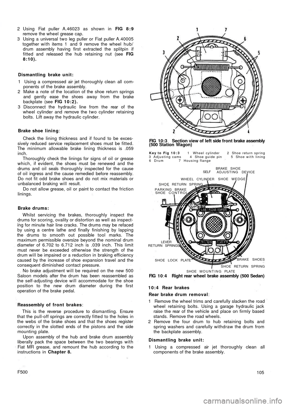
FIG 10:3 Section view of left side f r o n t brake assembly
(500 Station Wagon)
Key to Fig 10:3 1 Wheel cylinder 2 Shoe return spring
3 Adjusting cams 4 Shoe guide pin 5 Shoe with lining
6 Drum 7 Housing flange
BRAKE SHOE
ADJUSTING DEVICE
SHOE WEDGE
SELF
WHEEL CYLINDER
SHOE RETURN SPRING
PARKING BRAKE
SHOE CONTROL
RETURN SPRINGS
LEVER
SHOE LOCK PLATEBRAKE SHOES
SHOE RETURN SPRING
SHOE MOUNTING PLATE
FIG 1 0:4 Right rear wheel brake assembly (500 Sedan)
10:4 Rear brakes
Rear brake drum removal:
1 Remove the wheel trims and carefully slacken the road
wheel retaining bolts. Using a garage hydraulic jack
raise the rear of t h e vehicle and place on firmly based
stands. Remove the road wheels.
2 Remove the four drum to hub retaining bolts and
spring washers and carefully withdraw the drum from
the backplate assembly.
Dismantling brake unit:
1 Using a compressed air jet thoroughly clean all
components of the brake assembly.
105
Page 102 of 128
10:9 Brake fluid reservoir
The reservoir is located in the front compartment to the
side of the fuel tank as shown in FIG 10:9. Should it be
necessary to detach the fluid outlet line from the reservoir
the outlet hole must be blanked off using a tapered
wooden peg of suitable length so that the cap may be
replaced to prevent the ingress of foreign matter into
the reservoir and the absorbtion of moisture, oil or petrol
vapours which would alter the properties of the hydraulic
fluid.
A special filter is fitted into the top of the reservoir
through which all fluid used for topping-up the reservoir
must pass to ensure utmost inner cleanliness of the
hydraulic system.
10:10 Bleeding the system
This is not a routine maintenance operation and is only
necessary if air has entered the hydraulic system because
parts have been dismantled or because the f l u i d level in
the reservoir has dropped so low that air has been drawn
into the main feed pipe to the master cylinders.
1 Fill the reservoir w i t h Fiat 'Blue Label' hydraulic fluid.
During the bleeding operation fluid will be used and
constant topping-up of the supply reservoir will be
needed. If this is not done it is possible for air to enter
the master cylinder main feed pipe which will nullify
the operation and necessitate a fresh start.
2 Attach a length of rubber or plastic tubing to the
bleeder screw on the rear wheel cylinder furthermost
from the master cylinder. Immerse the free end of the
tube in a small volume of hydraulic brake fluid in a
clean jar.
3 Open the bleed screw one turn and get a second
operator to press down slowly on the brake pedal. After
a full stroke let the pedal return without assistance,
pause a moment and repeat the d o w n stroke. At first
there will be air bubbles issuing from the bleed tube,
but when fluid alone is ejected, hold the pedal firmly
down on the floor panel and tighten the bleed screw.
Repeat this operation on the other rear brake and then
repeat the operation on the two front brakes.
4 On completion, top-up the fluid in the reservoir to the
correct level. Discard all dirty fluid. If fluid is perfectly
clean, let it stand for twenty four hours to become
clear of air bubbles before using it again.
10:11 Hand parking brake
Normally with the new 500 Sedan model automatic
brake adjusting device, adjustment of the rear brakes
will take up excessive handbrake travel.
If there is excessive travel on the handbrake of the
Sedan model at any time, or in the case of Station Wagon
model even after the rear brakes have been manually
adjusted, suspect worn brake shoe linings or stretched
handbrake cables. Examine the linings and fit replace-
ment shoes if necessary. Check the action of the hand
parking brake again and if there is still too much travel
before the brakes are applied it is permissible to take up as
follows:
1 It is essential to ensure that the rear shoes are correctly
adjusted as described in Section 10:2.
2 Apply the hand parking brake lever until the pawl
engages with the ratchet at the second notch.
F500
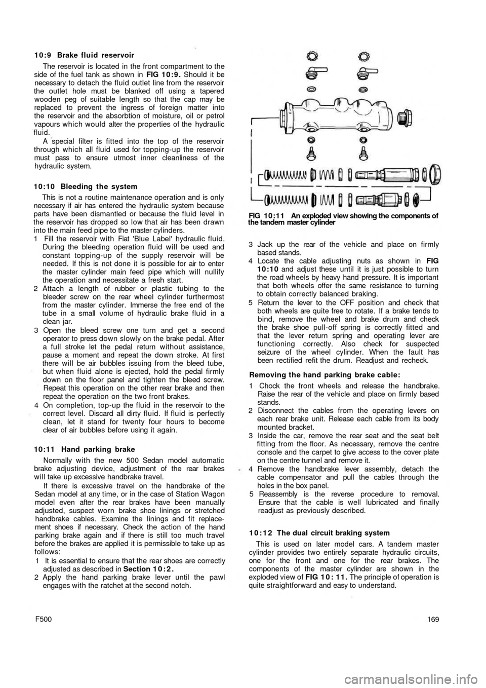
FIG 10:11 An exploded view showing the components of
the tandem master cylinder
3 Jack up the rear of t h e vehicle and place on firmly
based stands.
4 Locate the cable adjusting nuts as shown in FIG
10:10 and adjust these until it is just possible to turn
the road wheels by heavy hand pressure. It is important
that both wheels offer the same resistance to turning
to obtain correctly balanced braking.
5 Return the lever to the OFF position and check that
both wheels are quite free to rotate. If a brake tends to
bind, remove the wheel and brake drum and check
the brake shoe pull-off spring is correctly fitted and
that the lever return spring and operating lever are
functioning correctly. Also check for suspected
seizure of the wheel cylinder. When the fault has
been rectified refit the drum. Readjust and recheck.
Removing the hand parking brake cable:
1 Chock the front wheels and release the handbrake.
Raise t h e rear of the vehicle and place on firmly based
stands.
2 Disconnect the cables from the operating levers on
each rear brake unit. Release each cable from its body
mounted bracket.
3 Inside the car, remove the rear seat and the seat belt
fitting from the floor. As necessary, remove the centre
console and the carpet to give access to the cover plate
on the centre tunnel and remove it.
4 Remove the handbrake lever assembly, detach the
cable compensator and pull the cables through the
holes in the box panel.
5 Reassembly is the reverse procedure to removal.
Ensure t h a t the cable is well lubricated and finally
readjust as previously described.
10:12 The dual circuit braking system
This is used on later model cars. A tandem master
cylinder provides t w o entirely separate hydraulic circuits,
one for the front and one for the rear brakes. The
components of the master cylinder are shown in the
exploded view of FIG 1 0 : 1 1 . The principle of operation is
quite straightforward and easy to understand.
169