remove seats FIAT 500 1967 1.G Workshop Manual
[x] Cancel search | Manufacturer: FIAT, Model Year: 1967, Model line: 500, Model: FIAT 500 1967 1.GPages: 128, PDF Size: 9.01 MB
Page 11 of 128
INTAKEEXHAUSTINTAKEEXHAUST
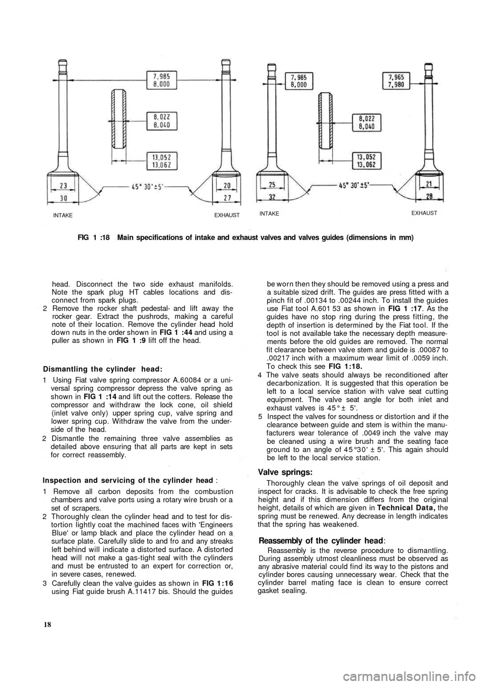
FIG 1 :18 Main specifications of intake and exhaust valves and valves guides (dimensions in mm)
head. Disconnect the t w o side exhaust manifolds.
Note the spark plug HT cables locations and dis-
connect from spark plugs.
2 Remove the rocker shaft pedestal- and lift away the
rocker gear. Extract the pushrods, making a careful
note of their location. Remove the cylinder head hold
down nuts in the order shown in FIG 1 :44 and using a
puller as shown in FIG 1 :9 lift off the head.
Dismantling the cylinder head:
1 Using Fiat valve spring compressor A.60084 or a uni-
versal spring compressor depress the valve spring as
shown in FIG 1 :14 and lift out the cotters. Release t h e
compressor and withdraw the lock cone, oil shield
(inlet valve only) upper spring cup, valve spring and
lower spring cup. Withdraw the valve from the under-
side of the head.
2 Dismantle the remaining three valve assemblies as
detailed above ensuring that all parts are kept in sets
for correct reassembly.
Inspection and servicing of the cylinder head :
1 Remove all carbon deposits from the combustion
chambers and valve ports using a rotary wire brush or a
set of scrapers.
2 Thoroughly clean the cylinder head and to test for dis-
tortion lightly coat the machined faces with 'Engineers
Blue' or lamp
black and place the cylinder head on a
surface plate. Carefully slide to and fro and any streaks
left behind will indicate a distorted surface. A distorted
head will not make a gas-tight seal with the cylinders
and must be entrusted to an expert for correction or,
in severe cases, renewed.
3 Carefully clean the valve guides as shown in FIG 1:16
using Fiat guide brush A.11417 bis. Should the guides
18Reassembly is the reverse procedure to dismantling.
During assembly utmost cleanliness must be observed as
any abrasive material could find its way to the pistons and
cylinder bores causing unnecessary wear. Check that the
cylinder barrel mating face is clean to ensure correct
gasket sealing.Reassembly of t h e cylinder head:
be worn then they should be removed using a press and
a suitable sized drift. The guides are press fitted with a
pinch fit of .00134 to .00244 inch. To install the guides
use Fiat tool A.601 53 as shown in FIG 1 :17. As the
guides have no stop ring during the press fitting, the
depth of insertion is determined by the Fiat tool. If the
tool is not available take the necessary depth measure-
ments before the old guides are removed. The normal
fit clearance between valve stem and guide is .00087 to
.00217 inch with a maximum wear limit of .0059 inch.
To check this see FIG 1:18.
4 The valve seats should always be reconditioned after
decarbonization. It is suggested that this operation be
left to a local service station with valve seat cutting
equipment. The valve seat angle for both inlet and
exhaust valves is 4 5 ° ± 5'.
5 Inspect the valves for soundness or distortion and if the
clearance between guide and stem is within the manu-
facturers wear tolerance of .0049 inch the valve may
be cleaned using a wire brush and the seating face
ground to an angle of 45°30' ± 5'. This again should
be left to the local service station.
Valve springs:
Thoroughly clean the valve springs of oil deposit and
inspect for cracks. It is advisable to check the free spring
height and if this dimension differs from the original
height, details of which are given in Technical Data, the
spring must be renewed. Any decrease in length indicates
that the spring has weakened.
Page 16 of 128
tolerance range of .00043 to .00240 inch or less than
.0059 inch the bearing inserts may be used again with-
out any need for regrinding. Should however the
clearance be greater than .0059 inch the inserts must be
renewed, using undersize inserts if the crankpin journals
have been reground.
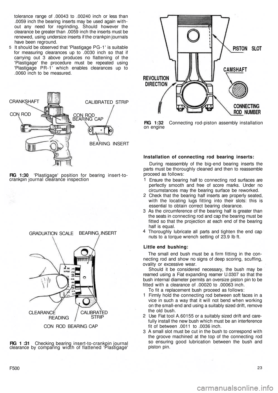
It should be observed that 'Plastigage PG-1' is suitable
for measuring clearances up to .0030 inch so that if
carrying out 3 above produces no flattening of the
'Plastigage' the procedure must be repeated using
'Plastigage PR-1' which enables clearances up to
.0060 inch to be measured.
5
CRANKSHAFT
CON RODCALIBRATED STRIP
CON ROD
BEARING CAP
BEARING INSERT
FIG 1:30 'Plastigage' position for bearing insert-to-
crankpin journal clearance inspection
GRADUATION SCALE
BEARING .INSERT
CLEARANCE
READINGCALIBRATED
STRIP
CON ROD BEARING CAP
FIG 1 :31 Checking bearing insert-to-crankpin journal
clearance by comparing width of flattened 'Plastigage'
F50023
To fit a replacement bush proceed as follows:
Firmly hold the connecting rod between soft faces in a
vice in such a way that it will not bend when working
on the small-end and using a suitably sized drift, remove
the old bush.
Use Fiat tool A.60155 or a suitably sized drift and care-
fully install the new bush which must be an interference
fit of between .0011 to .0036 inch.
A small slot must be cut in the bush to correspond w i t h
the groove machined at the top of the connecting rod
so ensuring good lubrication between the bush and
piston pin. 1
2
3The small end bush must be a firm fitting in the con-
necting rod and show no signs of deep scoring, scuffing,
ovality or excessive wear.
Should it be considered necessary, the bush may be
reamed using a Fiat expanding reamer U.0307 so that the
bush internal diameter permits an oversize piston pin to be
fitted with a clearance of .00020 to .00063 inch. Little end bushing:Installation of connecting rod bearing inserts:
During reassembly of the big-end bearing inserts the
parts must be thoroughly cleaned and then to reassemble
proceed as follows:
Ensure the bearing half to connecting rod surfaces are
perfectly smooth and free of score marks. Under no
circumstances may the bearing surface be reworked.
Check that the bearing half inserts are properly seated,
with the locating lugs fitting into their slots: this is
essential to obtain
correct bearing clearance.
As the circumference of the bearing half is greater than
the seats in connecting rod and cap the bearing must be
fitted so that the projection at each end of the bearing
half is equal.
Thoroughly lubricate all parts and tighten the end cap
nuts to a torque wrench setting of 23.9 Ib ft. 1
2
3
4FIG 1:32 Connecting rod-piston assembly installation
on engine
REVOLUTION
DIRECTIONPISTON SLOT
CAMSHAFT
CONNECTING
ROD NUMBER
Page 22 of 128
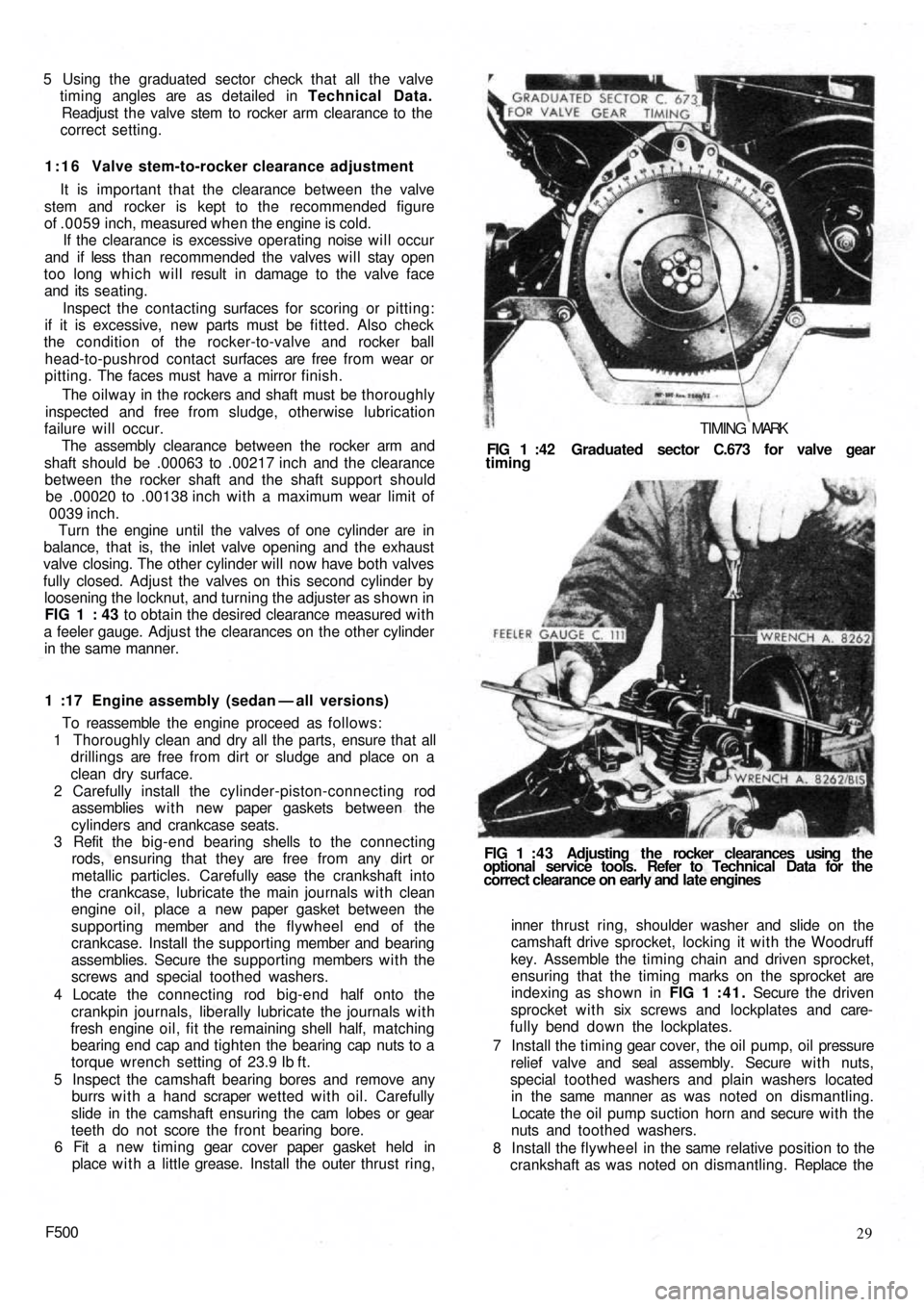
5 Using the graduated sector check that all the valve
timing angles are as detailed in Technical Data.
Readjust the valve stem to rocker arm clearance to the
correct setting.
1:16 Valve stem-to-rocker clearance adjustment
It is important that the clearance between the valve
stem and rocker is kept to the recommended figure
of .0059 inch, measured when the engine is cold.
If the clearance is excessive operating noise will occur
and if less than recommended the valves will stay open
too long which will result in damage to the valve face
and its seating.
Inspect the contacting surfaces for scoring or pitting:
if it is excessive, new parts must be fitted. Also check
the condition of the rocker-to-valve and rocker ball
head-to-pushrod contact surfaces are free from wear or
pitting. The faces must have a mirror finish.
The oilway in the rockers and shaft must be thoroughly
inspected and free from sludge, otherwise lubrication
failure will occur.
The assembly clearance between the rocker arm and
shaft should be .00063 to .00217 inch and the clearance
between the rocker shaft and the shaft support should
be .00020 to .00138 inch with a maximum wear limit of
0039 inch.
Turn the engine until the valves of one cylinder are in
balance, that is, the inlet valve opening and the exhaust
valve closing. The other cylinder will now have both valves
fully closed. Adjust the valves on this second cylinder by
loosening the locknut, and turning the
adjuster as shown in
FIG 1 : 43 to obtain the desired clearance measured with
a feeler gauge. Adjust the clearances on the other cylinder
in the same manner.
1 :17 Engine assembly (sedan — all versions)
To reassemble the engine proceed as follows:
1 Thoroughly clean and dry all the parts, ensure that all
drillings are free from dirt or sludge and place on a
clean dry surface.
2 Carefully install the cylinder-piston-connecting rod
assemblies w i t h new paper gaskets between the
cylinders and crankcase seats.
3 Refit the big-end bearing shells to the connecting
rods, ensuring that they are free from any dirt or
metallic particles. Carefully ease t h e crankshaft into
the crankcase, lubricate the main journals with clean
engine oil, place a new paper gasket between the
supporting member and the flywheel end of the
crankcase. Install the supporting member and bearing
assemblies. Secure the supporting members with the
screws and special toothed washers.
4 Locate the connecting rod big-end half onto the
crankpin journals, liberally lubricate the journals with
fresh engine oil, fit the remaining shell half, matching
bearing end cap and tighten the bearing cap nuts to a
torque wrench setting of 23.9 Ib ft.
5 Inspect the camshaft bearing bores and remove any
burrs w i t h a hand scraper wetted with oil. Carefully
slide in the camshaft ensuring the cam lobes or gear
teeth do not score the front bearing bore.
6 Fit a new timing gear cover paper gasket held in
place w i t h a little grease. Install the outer thrust ring,
F50029 inner thrust ring, shoulder washer and slide on the
camshaft drive sprocket, locking it with the Woodruff
key. Assemble the timing chain and driven sprocket,
ensuring that the timing marks on the sprocket are
indexing as shown in FIG 1 :41. Secure the driven
sprocket with six screws and lockplates and care-
fully bend down the lockplates.
7 Install the timing gear cover, the oil pump, oil pressure
relief valve and seal assembly. Secure w i t h nuts,
special toothed washers and plain washers located
in the same manner as was noted on dismantling.
Locate the oil pump suction horn and secure with the
nuts and toothed washers.
8 Install the flywheel in the same relative position to the
crankshaft as was noted on dismantling. Replace the FIG 1 : 4 3 Adjusting the rocker clearances using the
optional service tools. Refer to Technical Data for the
correct clearance on early and late engines FIG 1 :42 Graduated sector C.673 for valve gear
timing
TIMING MARK
Page 53 of 128
*Dimension to be obtained by
adjusting the throwout lever.
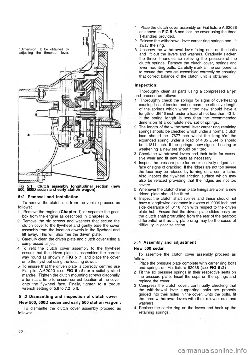
FIG 5:1 Clutch assembly longitudinal section (new
500, 500D sedan and early station wagon)
5 : 2 Removal and installation
To remove the clutch unit from the vehicle proceed as
follows:
1 Remove the engine (Chapter 1) or separate the gear-
box from the engine as described in Chapter 6.
2 Remove the six screws and washers that secure the
clutch cover to the flywheel and gently ease the cover
assembly from the location dowels in the flywheel and
lift away. This will also free the driven plate.
3 Carefully clean the driven plate and clutch cover using a
compressed air jet.
4 To refit the clutch cover assembly to the flywheel
ensure that the driven plate is assembled the correct
way round as shown in FIG 5 :1 and place the cover
onto the flywheel using the locating dowels.
5 To ensure that the driven plate is correctly centred use
Fiat pilot A.62023 (see FIG 5 : 5) or a suitably sized
mandrel. Tighten the clutch mounting screws diagonally
a turn at a time to ensure correct location of the cover
onto the flywheel face. Finally, tighten to a torque
wrench setting of 5.8 to 7.2 Ib ft.
5 :3 Dismantling and inspection of clutch cover
New 500, 500D sedan and early 500 station wagon :
To dismantle the clutch cover assembly proceed as
follows:
60
To assemble the clutch cover assembly proceed as
follows:
1 Place the pressure plate complete with carrier ring bolts
and springs on Fiat fixture 62038 (see FIG 5 : 2).
2 Fit the six pressure springs in their respective seats on
the pressure plate. Insert the cups on the springs and
replace the cover.
3 Compress the clutch cover, continually checking that
the withdrawal lever supporting bolts are properly
guided into their holes in the cover. Onto the bolts, fit
the three withdrawal levers w i t h their relevant nuts and
washers.
4 Replace the carrier ring on the levers and hook up the
retaining springs. 5 :4 Assembly and adjustment
N e w 500 sedan1 Place the clutch cover assembly on Fiat fixture A.62038
as shown in FIG 5 :6 and lock the cover using the three
T-handles provided.
2 Release the w i thdrawal lever carrier ring springs and lift
away the ring.
3 Unscrew the withdrawal lever fixing nuts on the bolts
and lift out the levers and washers. Gradually slacken
the three T-handles so relieving the pressure of the
clutch springs. Remove the clutch cover, springs and
lever mounting bolts. Carefully mark all the components
to ensure that they are assembled correctly so ensuring
that correct balance of the clutch unit is obtained.
Inspection:
Thoroughly clean all parts using a compressed air jet
and proceed as follows:
1 Thoroughly check the springs for signs of overheating
causing loss of tension and compare the effective length
of the springs which when fitted new should have a
length of .9646 inch under a load of not less than 43 Ib.
If the spring length is less t h a n t h e recommended
dimension fit a complete new set of springs.
2 The length of the withdrawal lever carrier ring retaining
springs should be checked which under a normal clutch
load should be .7677 inch whilst the length'of the
expanded spring under a load of 4.85 ± .44 Ib should
be 1.1811 inch. If the springs show sign of heating or
weakening a new set should be fitted.
3 Check the withdrawa l levers and their bolts for exces-
sive wear and fit new parts as necessary.
4 Inspect the pressure plate for an excessively ridged sur-
face or signs of cracking. If the ridges are not too severe
the face may be refaced by turning on a centre lathe.
Also inspect the flywheel friction surface which may
also be refaced providing that the ridges are not too
severe.
5 Whenever the clutch driven plate linings are worn a new
driven plate should be fitted.
6 Inspect the clutch shaft splines and these should not
have a lengthwise clearance in excess of .0039 inch and
side clearance of .0118 inch w i t h respect to the driven
plate hub. Ensure that the driven plate slides easily on
the clutch shaft protruding from the rear of the gearbox
differential unit as any plate drag may be the cause of
d i f f i c u l t y in gear selection.
Page 59 of 128
PRIMARY SHAFT-TO-CLUTCH
SHAFT MOUNTING PINCLUTCH SHAFT SEAL PRIMARY SHAFT WITH
1st, 3 r d A N D 4 t h SPEED
GEAR CLUSTER
2 n d SPEED
DRIVE GEARPRIMARY SHAFT
FRONT BALL BEARINGPRIMARY SHAFT
REAR BALL BEARING
PRIMARY
SHAFT-TO-CLUTCH
i SHAFT JOINING SLEEVEJOINING SLEEVELOCKRING
SPEED SELECTOR LEVER
CLUTCH SHAFT
LAYSHAFT WITH BEVEL PINION
SPEEDOMETER DRIVE GEAR
2 n d SPEED ENGAGEMENT
SLIDING SLEEVE
2 N D SPEED DRIVEN GEAR
LAYSHAFT FRONT BALL
BEARING
3 r d SPEED DRIVEN GEARHUB FOR
SLEEVE
3rd AND 4th/
SPEED ENGAGEMENT
SLIDING SLEEVE4 t h SPEED
DRIVEN GEARLAYSHAFT REAR ROLLER BEARING
LAYSHAFT-TO-PINION
ADJUSTMENT WASHER 1st SPEED AND)
REVERSE SLIDING GEAR
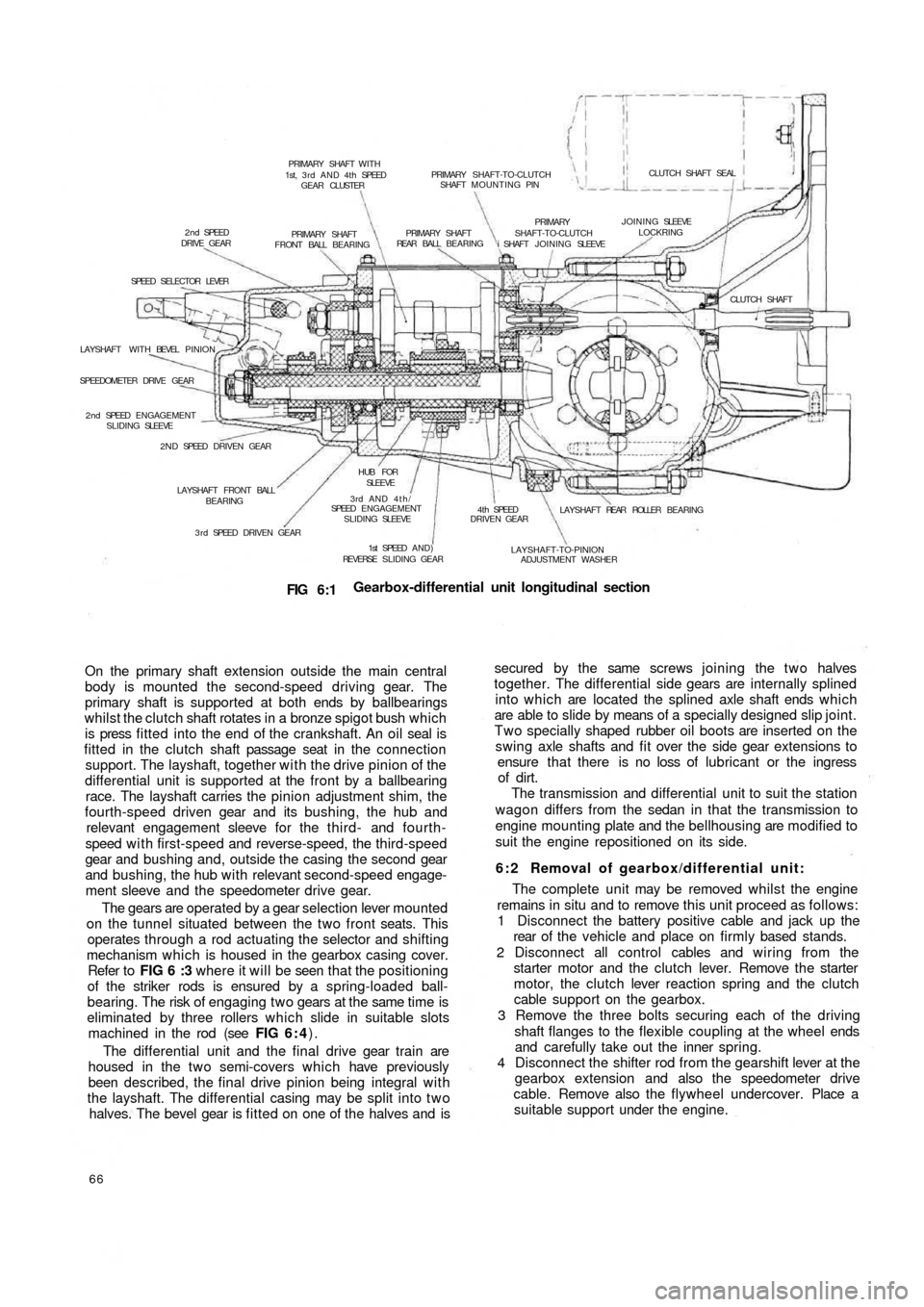
FIG 6:1Gearbox-differential unit longitudinal section
On the primary shaft extension outside the main central
body is mounted the second-speed driving gear. The
primary shaft is supported at both ends by ballbearings
whilst the clutch shaft rotates in a bronze spigot bush which
is press fitted into the end of the crankshaft. An oil seal is
fitted in the clutch shaft passage seat in the c o n n e c t i o n
support. The layshaft, together with the drive pinion of the
differential unit is supported at the front by a ballbearing
race. The layshaft carries the pinion adjustment shim, the
fourth-speed driven gear and its bushing, the hub and
relevant engagement sleeve for the t h i r d - and fourth-
speed w i t h first-speed and reverse-speed, the third-speed
gear and bushing and, outside the casing the second gear
and bushing, the hub with relevant second-speed engage-
ment sleeve and the speedometer drive gear.
The gears are operated by a gear selection lever mounted
on the tunnel situated between the two front seats. This
operates through a rod actuating the selector and shifting
mechanism which is housed in the gearbox casing cover.
Refer to FIG 6 :3 where it will be seen th a t the positioning
of the striker rods is ensured by a spring-loaded ball-
bearing. The risk of engaging two gears at the same time is
eliminated by three rollers which slide in suitable slots
machined in the rod (see FIG 6 : 4).
The differential unit and the final drive gear train are
housed in the t w o semi-covers which
have previously
been described, the final drive pinion being integral with
the layshaft. The differential casing may be split into t w o
halves. The bevel gear is fitted on one of the halves and is
66
secured by the same screws joining the two halves
together. The differential side gears are internally splined
into which are located the splined axle shaft ends which
are able to slide by means of a specially designed slip joint.
Two specially shaped rubber oil boots are inserted on the
swing axle shafts and fit over the side gear extensions to
ensure that there is no loss of lubricant or the ingress
of dirt.
The transmission and differential unit to suit the station
wagon differs from the sedan in that the transmission to
engine mounting plate and the bellhousing are modified to
suit the engine repositioned on its side.
6 : 2 Removal of gearbox/differential unit:
The complete unit may be removed whilst the engine
remains in situ and to remove this unit proceed as follows:
1 Disconnect the battery positive cable and jack up the
rear of t h e vehicle and place on firmly based stands.
2 Disconnect all control cables and wiring from the
starter motor and the clutch lever. Remove the starter
motor, the clutch lever reaction spring and the clutch
cable support on the gearbox.
3 Remove the three bolts securing each of the driving
shaft flanges to the flexible coupling at the wheel ends
and carefully take out the inner spring.
4 Disconnect the shifter rod from the gearshift lever at the
gearbox extension and also the
speedometer drive
cable. Remove also the flywheel undercover. Place a
suitable support under the engine.
Page 62 of 128
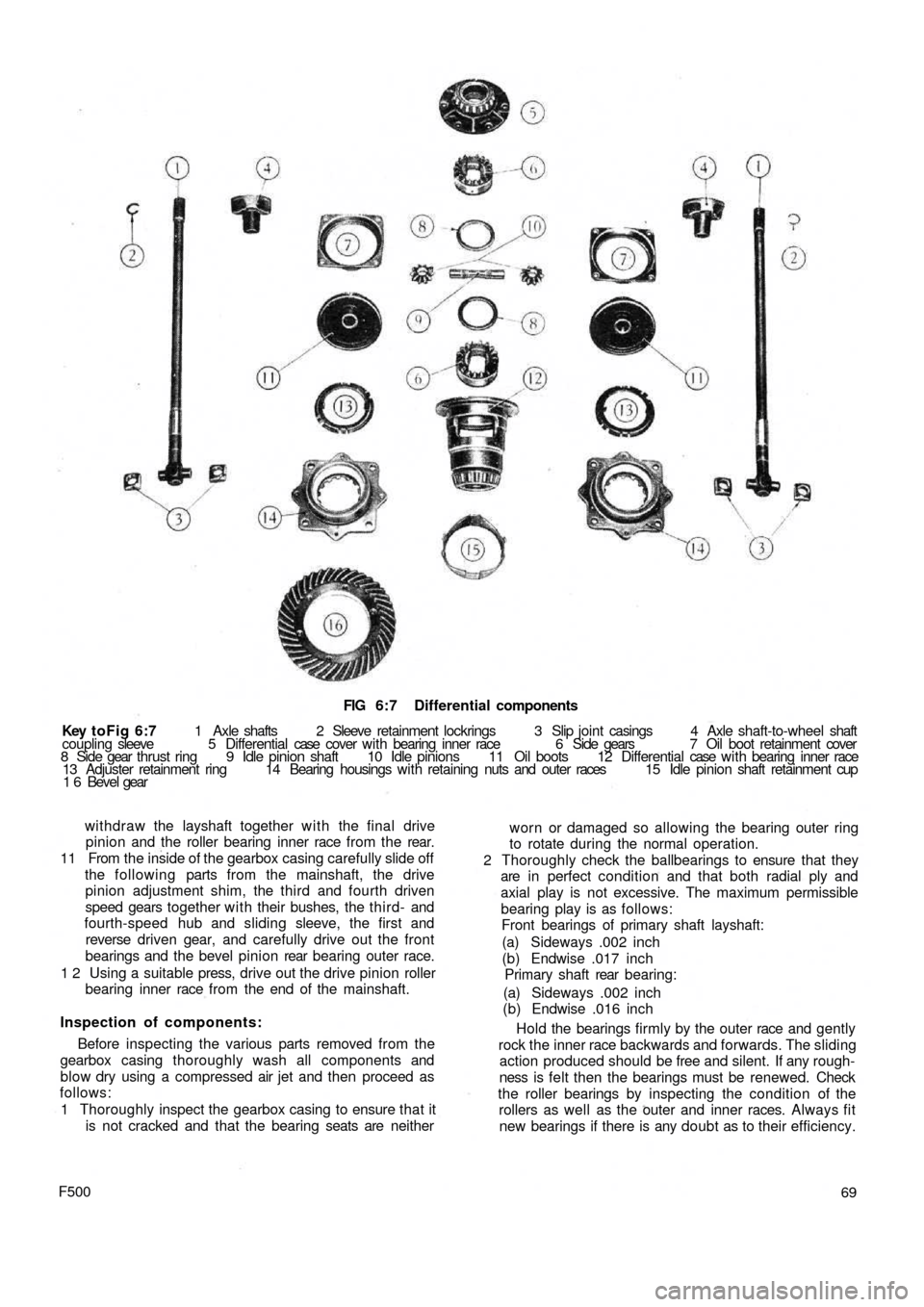
FIG 6:7 Differential components
Key toFig 6:7 1 Axle shafts 2 Sleeve retainment lockrings 3 Slip joint casings 4 Axle shaft-to-wheel shaft
coupling sleeve 5 Differential case cover w i t h bearing inner race 6 Side gears 7 Oil boot retainment cover
8 Side gear thrust ring 9 Idle pinion shaft 10 Idle pinions 11 Oil boots 12 Differential case w i t h bearing inner race
13 Adjuster retainment ring 14 Bearing housings with retaining nuts and outer races 15 Idle pinion shaft retainment cup
1 6 Bevel gear
withdraw the layshaft together w i t h the final drive
pinion and the roller bearing inner race from the rear.
11 From the inside of the gearbox casing carefully slide off
the following parts from the mainshaft, the drive
pinion adjustment shim, the third and fourth driven
speed gears together with their bushes, the t hird- and
fourth-speed hub and sliding sleeve, the first and
reverse driven gear, and carefully drive out the front
bearings and the bevel pinion rear bearing outer race.
1 2 Using a suitable press, drive out the drive pinion roller
bearing inner race from the end of the mainshaft.
Inspection of components:
Before inspecting the various parts removed from the
gearbox casing thoroughly wash all components and
blow dry using a compressed air jet and then proceed as
follows:
1 Thoroughly inspect the gearbox casing to ensure that it
is not cracked and that the bearing seats are neither
F50069 worn or damaged so allowing the bearing outer ring
to rotate during the normal operation.
2 Thoroughly check the ballbearings to ensure that they
are in perfect condition and that both radial ply and
axial play is not excessive. The maximum permissible
bearing play is as follows:
Front bearings of primary shaft layshaft:
(a) Sideways .002 inch
(b) Endwise .017 inch
Primary shaft rear bearing:
(a) Sideways .002 inch
(b) Endwise .016 inch
Hold the bearings firmly by the outer race and gently
rock the inner race backwards and forwards. The sliding
action produced should be free and silent. If any rough-
ness is felt then the bearings must be renewed. Check
the roller bearings by inspecting the condition of the
rollers as well as the outer and inner races. Always fit
new bearings if there is any doubt as to their efficiency.
Page 63 of 128
3 Check the layshaft and the primary shaft between
centres and using a dial gauge ensure that there is no
distortion. The out of true reading for bearing seats
should be less than .0008 inch. Inspect the splines and
ensure that the side and outerfaces are not indented.
Replace if there are signs of wear. Also inspect the
reverse shaft to ensure that it is perfectly smooth and
not showing signs of pitting or partial seizure.
4 Carefully inspect all gear teeth for signs of excessive
wear or damage. The contact faces must be smooth and
show no signs of indentation marks. Also check that
the backlash between the gears, when correctly
mounted on the surface plate is not greater than .0039
inch. The maximum wear limit is .0079 inch. Check that
the quick engagement front teeth of the second-, third-
and fourth-speed gears are not damaged or excessively
worn. Renew if there are signs of gearchange lever
misuse.
5 Inspect the sliding sleeves and the relevent hubs, ensure
that all the working surfaces are perfectly smooth. The
clearance between the mating parts should not be
greater than .0059 inch. Also inspect the meshing teeth
and ensure that they are in good condition.
6 Check that the gear shifting selector forks are not dis-
torted and that the striker rods freely slide in their seats
in the gearbox casing.
7 Carefully inspect that all the oil seals are in perfect con-
dition and if there is any doubt they should be renewed.
8 Inspect the striker rod locking balls and the safety rollers
and ensure that they slide freely in their seatings. Also
check the ball load spring efficiency and if this shows
signs of weakness then it should be renewed. Any
faults with these items will cause difficulty in engaging
gears or autodisengagement during engine acceleration.
6 : 4 Reassembly—gearbox
To reassemble the components to the gearbox ensure
that all components are thoroughly clean and then pro-
ceed as follows:
1 Press t h e pinion rear roller bearing onto the layshaft.
Install the layshaft in the casing, and at the same time
fit the adjustment shim, the fourth-speed driven gear
together w i t h its bush, the sleeve and hub for third and
fourth gear engagement, the first-speed and reverse
driven gear and the third-speed driven gear with its
hub.
2 Install the front layshaft ballbearing securing the
bearing retainment plate w i t h the screws and finally
lock the screws in position.
3 Insert the primary shaft together with the first, third
and fourth driving gear train in the gearbox housing
and slide t h e rear bearing onto the shaft. Push the
input shaft forward to enable the clutch shaft coupling
to be inserted in t h e rear and to be pulled up the
primary shaft by means of the pin. Do not forget the
retaining ring.
4 Slide the primary shaft backwards so pushing the rear
bearing into its bore. Refit the front bearing onto the
primary shaft.
5 On the layshaft insert the second-speed driven shaft
and bush, the second gear sliding dog sleeve and the
hub. Also insert the second-speed striker rod and the
first-speed fork. Do not forget to fit the safety roller
into its seating.
70
6 Slide the second-speed driving gear onto the primary
shaft. Place the engagement fork on the third- and
fourth-speed engagement sliding sleeve, and insert
the striker rod, lock the relevent fork and fit the safety
roller.
7 Insert the third safety roller and install the reverse shaft
and insert the reverse gear cluster onto it and secure
the shaft by tightening its block bolt. Install the reverse
striker rod w i t h its relevent fork.
8 Now refit the speedometer drive worm gear onto the
layshraft. Tighten the nuts on the primary shaft and the
layshaft, not forgetting to interpose the plain washer
between the speedometer driving worm and the nut,
to a torque wrench setting of 1 8.1 Ib ft to 25.3 Ib ft
(primary shaft) and 28.9 to 36.2 Ib ft (layshaft). It is
recommended that the input shaft and layshaft are
locked together by engaging t w o gears at the same
time. Finally, fit the splitpins.
9 Lock the shifter forks onto their shafts by tightening
their respective bolts and bend up the special locking
plates. Install the three positioning balls and relevant
springs into their bores and refit the cover plate.
10 Install the casing cover together with its relevant
gasket. This will enable correct positioning of the shift
shaft lever so that it engages in the outer ends of the
shifter shafts protruding from the gearbox casing.
11 Install the speedometer drive support on the gearbox
casing and refit the upper gearbox cover.
For subsequent differential operations and adjustments
see Sections 6:6.
6:5 Dismantling—differential and final drive
For the removal of the differential and final drive unit
from the gearbox refer to Section 6:3. To dismantle the
differential assembly
proceed as follows:
1 Remove the retaining ring 2 (see FIG 6 : 7) retaining
the splined sleeve 4 and slide the sleeve off the drive
shaft.
2 Remove t h e retaining covers 7 and the oil boots all
together with the bushes and seals, adjuster ring lock
rings 13, adjuster rings housing 14, and bearing
adjuster and roller bearing outer races.
3 Separate the differential housing halves by unscrewing
and removing the six bolts that keep both the halves and
the crownwheel together. It is advisable to mark the
respective components to ensure correct matching
upon reassembly.
4 Remove the differential pinion shaft retainer ring, also
the differential pinions 10 by removing the shaft and
withdrawing the two axle shafts 1.
5 Remove the differential side gears 6 and relevent thrust
rings 8.
6 Using a press remove the differential bearing inner
races from their seats on the carrier halves.
7 Thoroughly clean all parts and dry using a compressed
air jet.
Inspection:
The components of the differential unit must be
thoroughly inspected for correct operation and to deter-
mine the presence of any wear, damage or other irregulari-
ties. To check the items concerned proceed as follows:
1 Check thoroughly the idle pinion carrier shaft for signs
Page 73 of 128
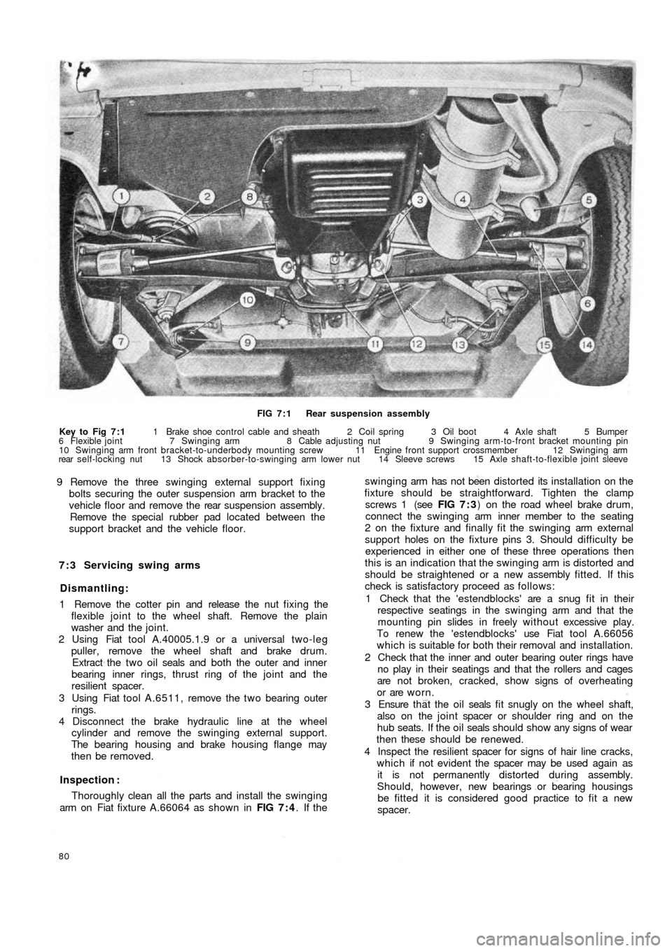
FIG 7 : 1 Rear suspension assembly
Key to Fig 7 : 1 1 Brake shoe control cable and sheath 2 Coil spring 3 Oil boot 4 Axle shaft 5 Bumper
6 Flexible joint 7 Swinging arm 8 Cable adjusting nut 9 Swinging arm-to-front bracket mounting pin
10 Swinging arm front bracket-to-underbody mounting screw 11 Engine front support crossmember 12 Swinging arm
rear self-locking nut 13 Shock absorber-to-swinging arm lower nut 14 Sleeve screws 15 Axle shaft-to-flexible joint sleeve
9 Remove the three swinging external support fixing
bolts securing the outer suspension arm bracket to the
vehicle floor and remove the rear suspension assembly.
Remove the special rubber pad located between the
support bracket and the vehicle floor.
7 : 3 Servicing swing arms
Dismantling:
1 Remove the cotter pin and release the nut fixing the
flexible joint to the wheel shaft. Remove the plain
washer and the joint.
2 Using Fiat tool A.40005.1.9 or a universal two-leg
puller, remove the wheel shaft and brake drum.
Extract the t w o oil seals and both the outer and inner
bearing inner rings, thrust ring of the joint and the
resilient spacer.
3 Using Fiat tool A.6511, remove the t w o bearing outer
rings.
4 Disconnect the brake hydraulic line at the wheel
cylinder and remove the swinging external support.
The bearing housing and brake housing flange may
then be removed.
Inspection :
Thoroughly clean all the parts and install the swinging
arm on Fiat fixture A.66064 as shown in FIG 7 : 4. If the
80
swinging arm has not been distorted its installation on the
fixture should be straightforward. Tighten the clamp
screws 1 (see FIG 7 : 3) on the road wheel brake drum,
connect the swinging arm inner member to the seating
2 on the fixture and finally fit the swinging arm external
support holes on the fixture pins 3. Should difficulty be
experienced in either one of these three operations then
this is an indication that the swinging arm is distorted and
should be straightened or a new assembly fitted. If this
check is satisfactory proceed as follows:
1 Check that the 'estendblocks' are a snug fit in their
respective seatings in the swinging arm and that the
mounting pin slides in freely w it h ou t excessive play.
To renew the 'estendblocks' use Fiat tool A.66056
which is suitable for both their removal and installation.
2 Check that the inner and outer bearing outer rings have
no play in their seatings and that the rollers and cages
are not broken, cracked, show signs of overheating
or are worn.
3 Ensure t h a t the o i l seals f i t snugly on the wheel shaft,
also on the joint spacer or shoulder ring and on the
hub seats. If the oil seals should show any signs of wear
then these should be renewed.
4 Inspect the resilient spacer for signs of hair line cracks,
which if not evident the spacer may be used again as
it is not permanently distorted during assembly.
Should, however, new bearings or bearing housings
be fitted it is considered good practice to fit a new
spacer.
Page 90 of 128
CHAPTER 9
THE STEERING SYSTEM
9 : 5 Relay lever and support
9 : 6 Steering rods
9 : 7 Front wheel toe-in
9 : 8 Fault diagnosis 9:1 Description
9 : 2 Steering wheel removal and refitting
9 : 3 Steering box removal and refitting
9 : 4 Steering box dismantling and reassembly
9:1 Description
The steering gear fitted to the new 500 range of
vehicles is of the worm screw and sector type with a
steering ratio of 1:13. The steering gearbox is located on
the front lefthand side of the dash wall on the scuttle as
shown in FIG 9:1. The steering gear comprises a pitman
arm and relay lever pivoting on a pin supported on the
body. A central track rod connects the pitman arm to the
relay lever. T w o track rods connect the pitman arm and
relay lever to the knuckle arms.
9:2 Steering wheel removal and refitting
To remove the steering wheel proceed as follows:
1 Disconnect the battery positive terminal clamp and
remove the horn control from the steering wheel.
2 Remove the cable from the push button seating and the
cable insulation sleeve.
3 Using a suitably sized box spanner or Fiat wrench
A.8279 unscrew the steering wheel to shaft nut as
shown in FIG 9:2.
4 Using the palm of the hands against the back of the
steering wheel rim gently tap the steering wheel
forwards so releasing it from the inner shaft.
F50097 5 Reassembly is the reverse procedure to dismantling.
Care should be taken to ensure that the front wheels
are located in the straight ahead position when the
steering wheel is being replaced otherwise the steering
wheel spokes will not be correctly positioned.
9 : 3 Steering box removal and refitting
To remove the steering box from the vehicle proceed
as follows:
1 From inside the vehicle remove the steering column
clamp bolt 6 (see FIG 9 : 3) after flattening the lock-
washer 7.
2 From the underside of the vehicle remove the t w o
tie rod locking nuts from the pitman arm and then using
Fiat tool A.46006 or a suitable t w o leg puller withdraw
the pins from the seats.
3 Remove the three nuts holding the steering box to the
body panel. Ease out the worm screw from the
steering shaft and lift away the steering box.
4 To refit the steering box is the reverse procedure to
dismantling. The steering box to body mounting nuts
should be tightened to a torque wrench setting of
14 Ib/ft to 18 Ib/ft.
Page 120 of 128
CHAPTER 12
THE BODYWORK
12:1
12:2
12:3
12:4
12:5
12:6
12:7Bodywork finish
Interior and chrome cleaning
Door trim and accessories
Door handles and locks
Removing regulator and door glass
Removing windshield glass
Removing rear side windows12:8
12:9
12:10
12:11
12:12
12:13
12:14Removing rear window glass
Front compartment lid
Engine compartment lid
Folding top
Sun roof
Seats
Interior heater
12:1 Bodywork finish
Large scale repairs to body panels are best left to
expert panel beaters. Even small dents can be tricky, as too
much hammering will stretch the metal and make things
worse instead of better. Filling minor dents and scratches
is probably the best method of restoring the surface. The
touching up of paintwork is well within the powers of
most car owners, particularly as self-spraying cans of
paint in the correct colours are now readily available. It
must be remembered, however, that paint changes colour
w i t h age and it is better to spray a whole wing rather than
try to touch up a small area.
Before spraying it is essential to remove all traces of
wax polish with white spirit. More drastic treatment is
required if silicone polishes have been applied. Use a
primer surfacer or paste stopper according to the amount
of filling required, and when it is dry, rub it down with
400 grade Wet or Dry paper until the surface is smooth
and flush with the surrounding area. Spend time on
getting the best finish as this will control the final effect.
Apply the retouching paint, keeping it wet in the centre
and light and dry round the edges. After a few hours of
drying, use a cutting compound to remove the dry spray
and finish with liquid polish.
F500127
12:2 Interior and chrome cleaning
The cloth upholstery of the seating and the rear
compartment lining must be regularly cleaned to ensure
long life and preserve its attractive appearance. Any dust
or dirt that is blown into the car will settle on the uphol-
stery and will tend to wear the cloth causing an unsightly
appearance. It is recommended that the dust is wiped off
using either a vacuum cleaner or a stiff brush. To remove
ordinary soiling of the upholstery cloth proceed as
follows:
1 Using luke warm water and a neutral soap and a piece
of clean cloth wipe over the upholstery in the direction
of the nap.
2 Repeat the operation using a clean damp cloth and
warm water but no soap.
3 Allow the upholstery cloth to dry, use a stiff brush
against the direction of the upholstery nap to restore
its original fluffy look.
To obtain best results, any stains must be removed as
soon as possible otherwise as time passes they will
become more difficult, if not impossible to remove.
Certain stains require specific solvents and the instruc-
tions must be strictly adhered to.