Generator FIAT 500 1968 1.G User Guide
[x] Cancel search | Manufacturer: FIAT, Model Year: 1968, Model line: 500, Model: FIAT 500 1968 1.GPages: 128, PDF Size: 9.01 MB
Page 25 of 128
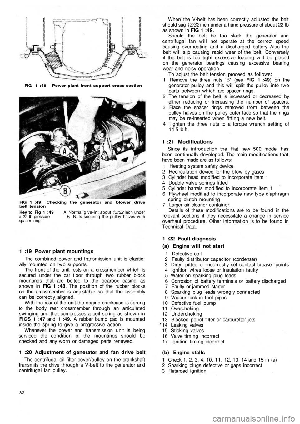
FIG 1 :48 Power plant front support cross-section
FIG 1 :49 Checking the generator and blower drive
belt tension
1 :19 Power plant mountings
The combined power and transmission unit is elastic-
ally mounted on two supports.
The front of the unit rests on a crossmember which is
secured under the car floor through two rubber block
mountings that are bolted to the gearbox casing as
shown in FIG 1 :48. The position of the rubber blocks
on the crossmember is adjustable so that the assembly
can be correctly aligned.
W i t h t h e rear of the unit the engine crankcase is sprung
to the b o d y rear crossmember through an articulated
swinging arm that compresses a coil spring as shown in
FIGS 1 :47 and 1 :49. A rubber bump pad is mounted
inside the spring to give a progressive action.
Whenever the power and transmission unit is being
serviced the condition of the mountings should be
checked and any worn or damaged parts renewed.
1 :20 Adjustment of generator and fan drive belt
The centrifugal oil filter cover/pulley on the crankshaft
transmits the drive through a V-belt to the generator and
centrifugal fan pulley.
32
(b) Engine stalls
1 Check 1, 2, 3, 4, 10, 1 1 , 12, 13, 14 and 15 in (a)
2 Sparking plugs defective or gaps incorrect
3 Retarded ignition 1 Defective coil
2 Faulty distributor capacitor (condenser)
3 Dirty, pitted or incorrectly set contact breaker points
4 Ignition wires loose or insulation faulty
5 Water on sparking plug leads
6 Corrosion of battery terminals or battery discharged
7 Faulty or jammed starter
8 Sparking plug leads wrongly connected
9 Vapour lock in fuel pipes
10 Defective fuel pump
11 Overchoking
12 Underchoking
13 Blocked petrol filter or carburetter jets
14 Leaking valves
15 Sticking valves
16 Valve timing incorrect
17 Ignition timing incorrect
(a) Engine will not start 1 :22 Fault diagnosis
Since its introduction the Fiat new 5 0 0 model has
been continually developed. The main modifications that
have been made are as follows:
1 Heating system safety device
2 Recirculation device for the blow-by gases
3 Cylinder head modified to incorporate item 1
4 Double valve springs fitted
5 Cylinder barrels modified to incorporate item 1
6 Flywheel modified to incorporate new type diaphragm
spring clutch mounting
7 Larger air cleaner container.
Details of these modifications are to be found in the
relevant sections if they necessitate a change in service
overhaul procedure. Other information is to be found in
Technical Data.
1 :21 Modifications
When the V-belt has been correctly adjusted the belt
should sag 13/32 inch under a hand pressure of about 22 lb
as shown in FIG 1 : 4 9.
Should the belt be too slack the generator and
centrifugal fan will not operate at the correct speed
causing overheating and a discharged battery. Also the
belt will slip causing rapid wear of the belt. Conversely
if the belt is too tight excessive loading will be placed
on the generator bearings causing excessive bearing
wear and noisy operation.
To adjust the belt tension proceed as follows:
1 Remove the three nuts ' B ' (see FIG 1 :49) on the
generator pulley and this will split the pulley into two
parts between which are spacer rings.
2 The tension of the belt is increased or decreased by
either reducing or increasing the number of spacers.
3 Place the spacer rings removed from between the
pulley halves on the pulley outer face so that the rings
may be re-inserted when fitting a new belt.
4 Tighten the three nuts to a torque wrench setting of
14.5
lb ft.
Key to Fig 1 :49 A Normal give-in: about 13/32 inch under
a 22 Ib pressure B Nuts securing the pulley halves with
spacer rings
Page 26 of 128
4 Mixture too weak
5 Water in fuel system
6 Petrol tank vent blocked
7 Incorrect valve clearance
(c) Engine idles badly
1 Check 1 and 6 in (b)
2 Air leak at manifold joints
3 Slow-running jet blocked or out of adjustment
4 Air leak in carburetter
5 Over-rich mixture
6 Worn piston rings
7 Worn valve stems or guides
8 Weak exhaust valve springs
(d) Engine misfires
1 Check 1, 2, 3, 4, 5, 8, 10, 13, 14, 1 5, 16, 17 in (a);
2, 3, 4 and 7 in (b)
2 Weak or broken valve springs
(e) Engine overheats
1 Generator and fan drive belt too loose
2 Shutter or thermostat seized in closed position
(f) Compression low
1 Check 14 and 15 in (a), 6 and 7 in (c) and 2 in (d)
2 Worn piston ring grooves
3 Scored or worn cylinder bores
(g) Engine lacks power
1 Check 3, 10, 1 1 , 13, 14, 15, 16 and 17 in (a), 2, 3, 4
and 7 in (b) 6 and 7 in (c) and 2 in (d). Also check (e)
and (f)
2 Leaking joint washers
3 Fouled sparking plugs
4 Automatic centrifugal advance not operating
(h) Burnt valves or seats
1 Check 14 and 15 in (a), 7 in (b) and 2 in (d). Alsocheck (e)
2 Excessive carbon around valve seat and head
(j) Sticking valves
1 Check 2 in (d)
2 Bent valve stem
3 Scored valve stem or guide
4 Incorrect valve clearance
(k) Excessive cylinder wear
1 Check 11 in (a) and see Chapter 4
2 Lack of oil
3 Dirty oil
4 Piston rings gummed up or broken
5 Badly fitting piston rings
6 Connecting rods bent
(l) Excessive oil consumption
1 Check 6 and 7 in (c) and check (k)
2 Ring gaps too wide
3 Oil return holes in piston choked with carbon
4 Scored cylinders
5 Oil level too high
6 External oil leaks
7 Ineffective valve stem oil seals
(m) Crankshaft and connecting rod bearing failure
1 Check 2 in (k)
2 Restricted oilways
3 Worn journals or crank pins
4 Loose bearing caps
5 Extremely low oil pressure
6 Bent connecting rod
(n) High fuel consumption (see Chapter 2)
(o) Engine vibration
1 Loose generator bolts
2 Blower blade assembly out-of-balance
3 Incorrect clearance for rear engine mounting rubber
F50033
Page 28 of 128
CHAPTER 2
THE FUEL SYSTEM
2:1 Description
2 : 2 Fuel pump operating principles
2 : 3 Routine maintenance
2 : 4 Pump removal, dismantling and examination
2 : 5 Reassembly, installation and adjustment
2 : 6 Carburetter operation and adjustment,
Weber 26.1MB2 : 7 Modifications
2 : 8 Carburetter operation and adjustment,
Weber 26.OC
2 :9 Air cleaner
2 : 1 0 B l o w - b y gases recirculation device
2:11 Fuel tank
2:12 Fault diagnosis
2:1 Description
All the new 500 models use a mechanical diaphragm
fuel feed pump as shown in FIG 2 : 1. Four types of
carburetter are fitted depending on the model to which
the engine is installed. Each carburetter operation and
adjustment is fully described, together with details of the
recirculation device for blow-by gases and o i l vapours.
2 : 2 Fuel pump operating principles
Refer to FIG 2 : 2. An eccentric on the rotating camshaft
actuates the operating rocker 21 via a pushrod 25 which
depresses the diaphragm 14 and so creates a depression
in the pumping chamber located in upper body 5. Under
atmospheric pressure, petrol passes through the pipeline
connection and inlet valve into the pumping chamber.
The return spring 15 then raises the diaphragm, expelling
the petrol through the outlet valve and pipeline to the
carburetter float chamber.
When the float chamber is full, the pressure in the pipe-
line and pumping chamber holds the diaphragm depressed
against the tension of the return spring.2 : 3 Routine maintenance
A poor delivery of fuel to the carburetter may be due to
a fault in the fuel pump or related lines. Periodically the
pump body screws 19 (see FIG 2 : 2) and upper cover
screw 1 should be checked for tightness. The fuel pump
lines should be disconnected and checked for freedom of
restriction, chafing and loose connections. The fuel pump
filter should be removed and cleaned periodically.
2:4 Pump removal, dismantling and examination
The pump is located on the carburetter side of the
engine crankcase (sedan) or under the generator at the
front of the crankcase (station wagon).
Removal:
1 Disconnect the fuel pipe from the tank to stop petrol
syphoning out of the tank and then release the fuel
inlet and outlet pipes from the pump body.
2 Remove the t w o nuts and washers holding pump to
crankcase.
3 Carefully lift away the pump, gaskets and insulating pad
from the crankcase (see FIG 2 : 3).
F50035
Page 40 of 128
3:1
3:2
3:3
3:4
3:5Description
Operation
Routine maintenance
Ignition faults
Removing and dismantling distributor (sedan
and sports)
CHAPTER 3
THE IGNITION SYSTEM
3:6
3:7
3:8
3:9
3:10
Removing and dismantling
(station wagon)
Timing the ignition
Sparking plugs
The distributor drive spindle
Fault diagnosisdistributor
3 :1 Description
The ignition system fitted to all the models covered by
this manual consists of an ignition coil, ignition distributor
fitted with contact breaker points, a centrifugal automatic
advance system, condenser, low- and high-tension
wiring, spark plugs and a power supply provided by a
generator and battery. The wiring diagram is shown in
FIG 3 : 1
1 The low-tension circuit which is sometimes called the
primary circuit includes the power supply, contact
breaker points, condenser and ignition coil primary
winding.
2 The high-tension circuit which is sometimes called the
secondary circuit includes the ignition coil secondary
winding, distributor rotor, distributor cap with terminals
and the central brush, high-tension cables and the spark
plugs.
3 : 2 Operation
The contact breaker unit in the distributor interrupts
the primary circuit by the points opening. The sudden stop
in the flow of current in the primary winding, does not cause
arcing at the contact breaker points because it discharges
into the condenser connected in parallel w i t h the contact
F50047
breaker points. With the sudden collapse of the primary
circuit, the intensity of the magnetic field drops causing
an induced high-tension current in the ignition coil
secondary winding. The high EMF is distributed to the
sparking plugs by the ignition distributor rotor.
The automatic advance mechanism comprises a plate
carrying t w o weights which are symmetrically pivoted on
the plate at one end. Also attached to the weights at
opposite ends to the pivots is the cam carrier shaft with
special tension return springs. Under the action of centri-
fugal force as the rotational speed increases, the weights
move outwards causing the cam carrier shaft to move
angularly compared to the distributor drive shaft thus
causing advancement of the ignition timing.
The contact breaker assembly comprises the cam on the
drive shaft and t w o contact points, one of which is
stationary while the other is under the influence of the
cam, the action of which is transmitted by a rubbing block.
The cam has t w o lobes to control the opening and closing
of contact points. The stationary contact point is mounted
on an adjustable support to enable the contact breaker
point gap to be adjusted.
The HT current reaches the distributor cap central
terminal, from the ignition coil and is distributed to each
of the spark plugs at the correct time by the rotor arm.
Page 46 of 128
CHAPTER 4
THE COOLING SYSTEM
4:1
4:2
4:3Description
Air outlet thermostat and shutter
Tension adjustment4:4
4:5
4:6Heating system safety device
Maintenance
Fault diagnosis
4:1Description
Sedan:
A l l the Fiat new 500 models covered by this manual are
aircooled by the forced air circulation system from a
centrifugal blower which is mounted on the generator
output shaft. The blower fan has fourteen vanes which are
arranged at various angles to reduce operating noise
during high-speed operation. A specially designed
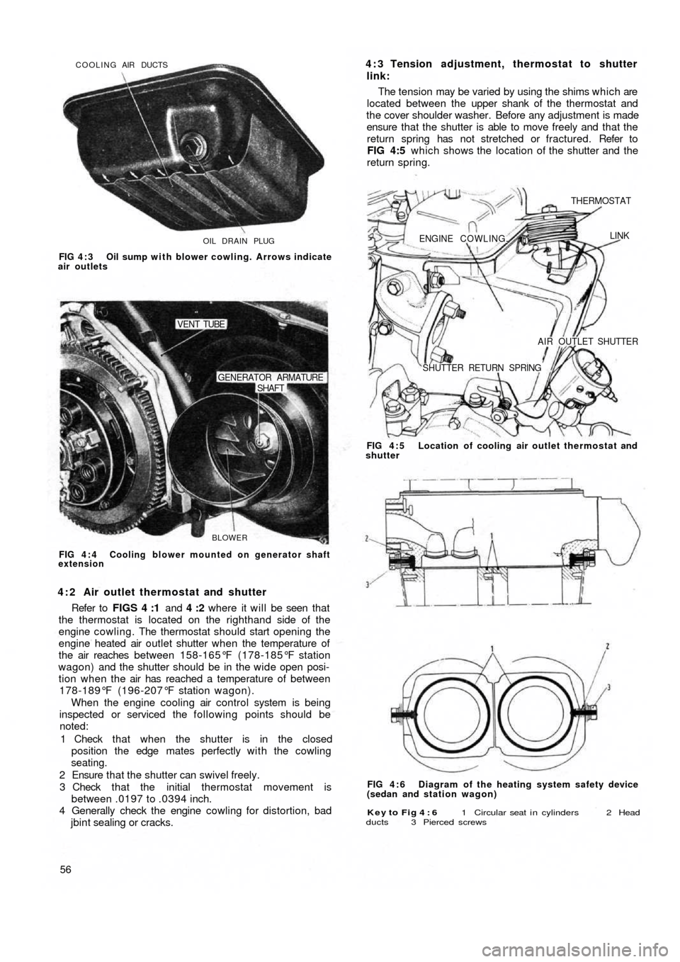
cowling as shown in FIGS 4 : 1 and 4:2 conveys the air
from the blower and distributes it to the various parts of
the exterior of the engine.
The main components of the air cooling system are as
follows:
1 Air intake compartment at the rear end of t h e body.
2 An elbow pipe for the admittance of incoming air.
3 A flexible air pipe connecting the elbow pipe to the
conveyor.
4 A spiral air conveyor which contains the centrifugal fan.
5 Distribution ducting for directing the air flow to various
parts of the engine.
6 A bellows type thermostat is fitted to the cowling which
operates a butterfly shutter controlling the air outlet
from the engine which ensures control of the engine
operating temperature.
F50053 When the shutter is in the open position, engine heated
air is allowed to disperse to the outside of the engine
cowling. With the shutter in its closed position, the air is
recirculated in the engine cowling so ensuring a quick
engine warm-up period.
It should be noted that by operating the heater lever
which is located on the centre tunnel at the rear seat,
warmed air flowing out from the engine cowling is passed
to the inside of the car for heating and demisting purposes.
Station wagon:
Refer to FIG 4 : 2 where it will be seen that as the engine
is located on its side underneath the luggage compartment
floor the ducting has been modified and the air intakes are
located at the rear of the side windows. A linear blower is
housed in the engine baffles and cowling and is attached
to the drive end of the generator.
The thermostat 'C' (see FIG 4 : 2) is located on the
righthand side of the engine cowling and should start
opening the engine heated air outlet shutter ' D ' when the
temperature of the air rises to 1 7 8 - 1 8 5 ° F and the shutter
should be wide open when the air is at a temperature of
196-207°F.
Page 49 of 128
OIL DRAIN PLUG COOLING AIR DUCTS
FIG 4 : 3 Oil sump with blower cowling. Arrows indicate
air outlets
BLOWER
SHAFT GENERATOR ARMATURE
VENT TUBE
FIG 4 : 4 Cooling blower mounted on generator shaft
extension
4 : 2 Air outlet thermostat and shutter
Refer to FIGS 4 :1 and 4 :2 where it will be seen that
the thermostat is located on the righthand side of the
engine cowling. The thermostat should start opening the
engine heated air outlet shutter when the temperature of
the air reaches between 158-165°F (178-185°F station
wagon) and the shutter should be in the wide open posi-
tion when the air has reached a temperature of between
178-189°F (196-207°F station wagon).
When the engine cooling air control system is being
inspected or serviced the following points should be
noted:
1 Check that when the shutter is in the closed
position the edge mates perfectly with the cowling
seating.
2 Ensure that the shutter can swivel freely.
3 Check that the initial thermostat movement is
between .0197 to .0394 inch.
4 Generally check the engine cowling for distortion, bad
jbint sealing or cracks.
56
Key to Fig 4 : 6 1 Circular seat i n cylinders 2 Head
ducts 3 Pierced screws
FIG 4 : 6 Diagram of the heating system safety device
(sedan and station wagon) FIG 4 : 5 Location of cooling air outlet thermostat and
shutter
ENGINE COWLING.
THERMOSTAT
LINK
AIR OUTLET SHUTTER
SHUTTER RETURN SPRING
4 : 3 Tension adjustment, thermostat to shutter
link:
The tension may be varied by using the shims which are
located between the upper shank of the thermostat and
the cover shoulder washer. Before any adjustment is made
ensure that the shutter is able to move freely and that the
return spring has not stretched or fractured. Refer to
FIG 4:5 which shows the location of the shutter and the
return spring.
Page 50 of 128
4 : 4 Heating system safety device
110F series sedan engines and later station wagon
engines incorporate a modification to the cylinder head
designed so that in the event of cylinder head gasket
failure exhaust gases are expelled outside the engine and
not leaked into the heating system.
The safety device comprises a square section circular
seat 1 (see FIG 4 :6) which is formed in the upper face of
the cylinder, a special duct in the cylinder head and a
pierced screw 3 for each cylinder.
The system is so designed that the exhaust gases are
released to the atmosphere from the circular seat in the
cylinder via the duct 2 and the pierced screw 3. It should
be noted that the screw 3 is also used for securing the
conveyor.
4 : 5 Maintenance
Due to the simple design of the air cooling system
maintenance has been kept to an absolute minimum and
should consist of the following checks:1 Inspect all the air conveyor system joints and ensure
that all the joint nuts and bolts are tight and that there
is no distortion between two joint faces.
2 Check that the tension of the generator and fan drive
belt is correct: with a hand pressure of approximately
22 Ib the belt should sag 13/32 inch. Adjust if necessary
as detailed in Chapter 1.
3 Ensure that the shutter can swivel freely and that the
spring is in a serviceable condition.
4 : 6 Fault diagnosis
(a) Engine overheating
1 Generator and fan drive belt slipping
2 Shutter control thermostat defective
3 Shutter unable to swivel freely
4 Shutter return spring broken
5 Leaking joints in conveyor system
F50057
Page 104 of 128
CHAPTER 11
THE ELECTRICAL EQUIPMENT
11:1 Description
11:2 Battery
11:3 The generator
11:4 The starter
11:5 The control box
1 1 : 6 Fuses
1 1 : 7 Flasher unit
11:1 Description
All models covered by this manual have 12 volts
electrical systems in which the negative battery terminal
is earthed. There are three units in the regulator box to
control the charging circuit; a cut-out, a current regulator
and a voltage regulator. These are adjustable but it must
be stressed that accurate moving coil meters are required
when checking or altering the settings. Cheap and
unreliable instruments will make accurate adjustments
impossible.
There are wiring diagrams in Technical Data at the end
of this manual to enable those with electrical experience
to trace and correct wiring faults.
For t h e U.K. Market the headlamps are of the double
filament dipping renewable bulb type with adjustments
for individual beam settings.
The battery is located in the front compartment
forward of the petrol tank and the fuses to the rear o f the
petrol tank.
Detailed instructions for servicing the electrical equip-
ment will be found in this chapter, but it must be pointed
out that it is not sensible to try to repair that which is
seriously defective, electrically or mechanically. Such
equipment should be replaced by new units which can
be obtained on an exchange basis.
F500111
11 :8 Windscreen wipers
1 1 : 9 The lighting system
11:10 Panel and warning lights
11:11 The horn
11:12 Lighting and flasher switch
1 1 : 1 3 Fault diagnosis
11.2 The battery
This of the 12-volt lead/acid type and has to meet
heavy demands for current particularly in the winter. To
maintain the performance of the battery at its maximum
it is essential to carry out the following operations.
Keep the top of the battery and surrounding parts dry
and clean, as dampness can cause leakage between the
securing clamps and the battery terminals. Clean off any
corrosion from the metal parts of the battery mounting
with diluted ammonia and paint them with an anti-
sulphuric paint. If the terminal posts are corroded,
remove the cables and clean w i t h diluted ammonia.
Smear the posts w i t h petroleum jelly before remaking the
connections and fit the terminals securely. High electrical
resistance due to corrosion at the terminal posts is often
responsible for lack of sufficient current to operate the
starter motor.
Ensure t h a t the filler plugs are in good condition and
show no signs of cracks. This may cause leakage of
electrolyte and consequent corrosion. Test the condition
of the cells after topping-up the electrolyte level with
distilled water to just above the tops of the separators as
shown in FIG 11 :2 . Never add neat acid. If it is
necessary to make a new electrolyte due to loss by
spillage add sulphuric acid to the
distilled water.
It is highly dangerous to add water to acid.
Page 105 of 128
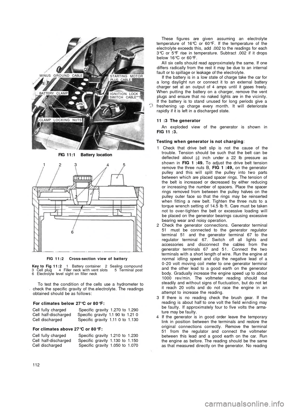
FIG 11:1 Battery location
CLAMP LOCKING NUTSIGNITION LOCK !
SWITCH CABLE*"? BATTERY CLAMP MINUS GROUND CABLE
STARTING MOTOR
PLUS CABLE
65
4 3
2 1
FIG 11:2 Cross-section view of battery
Key to Fig 11:2 1 Battery container 2 Sealing compound
3 Cell plug 4 Filler neck with vent slots 5 Terminal post
6 Electrolyte level sight on filler neck
To test the condition of the cells use a hydrometer to
check the specific gravity of the.electrolyte. The readings
obtained should be as follows:
For climates below 27°C or 80°F:
Cell fully charged Specific gravity 1.270 to 1.290
Cell half-discharged Specific gravity 1.1 90 to 1.21 0
Cell discharged Specific gravity 1.11 0 to 1.130
For climates above 27°C or 80°F:
Cell fully charged Specific gravity 1.210 to 1.230
Cell half-discharged Specific gravity 1.130 to 1.150
Cell discharged Specific gravity 1.050 to 1.070
112These figures are given assuming an electrolyte
temperature of 16°C or 60°F. If the temperature of the
electrolyte exceeds this, add .002 to the readings for each
3°C or 5°F rise in temperature. Subtract .002 if it drops
below 16°C or 60°F.
All six cells should read approximately the same. If one
differs radically from the rest it may be due to an internal
fault or to spillage or leakage of the electrolyte.
If the battery is in a low state of charge take the car for
a long daylight run or connect it to an external battery
charger set at an output of 4 amps until it gases freely.
When putting the battery on a charger, remove the vent
plugs and ensure that no naked lights are in the vicinity.
If the battery is to stand unused for long periods give a
freshening up charge every month. It will deteriorate
rapidly if it is left in a discharged state.
11 :3 The generator
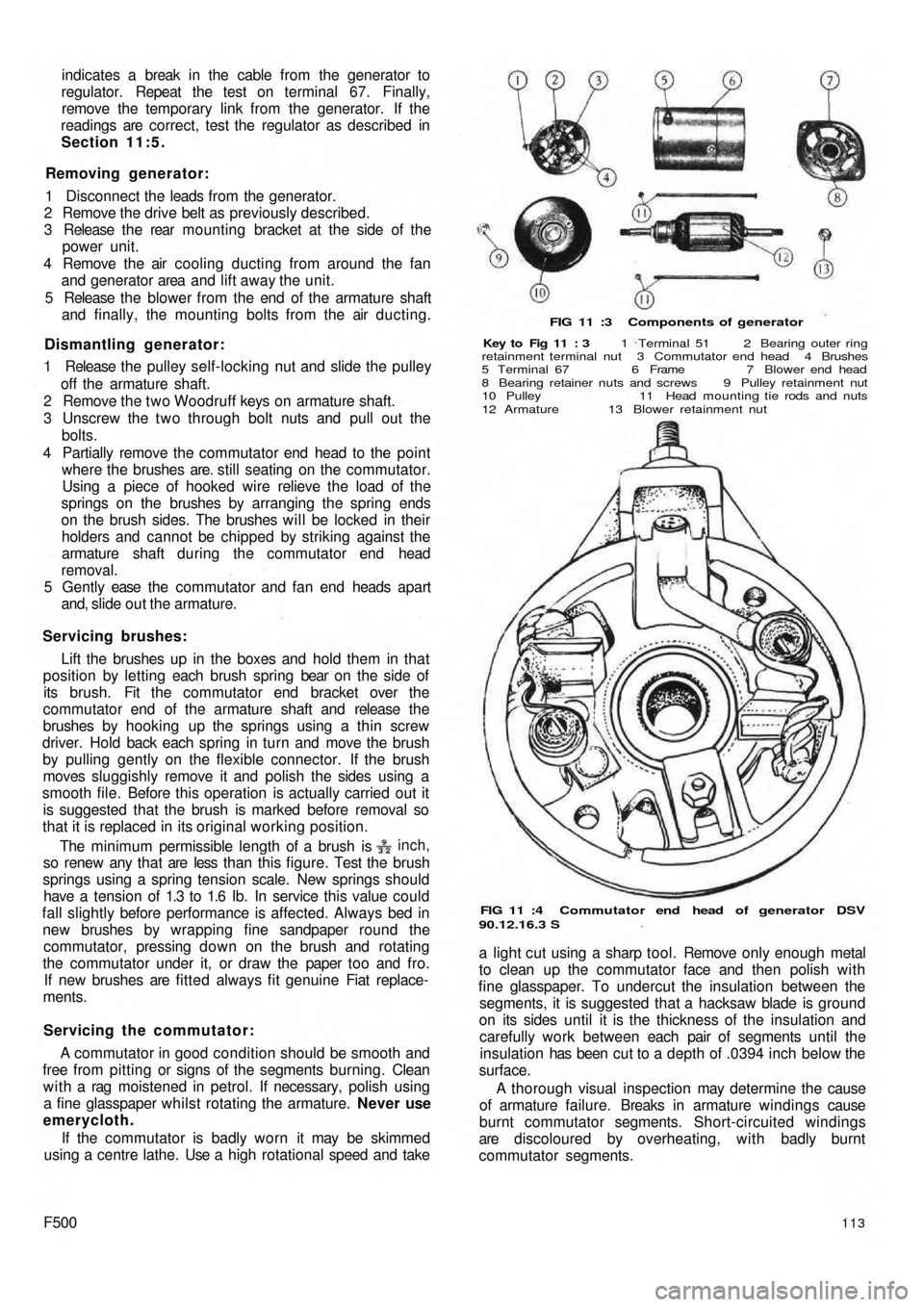
An exploded view of the generator is shown in
FIG 11 : 3 .
Testing when generator is not charging:
1 Check that drive belt slip is not the cause of the
trouble. Tension should be such that the belt can be
deflected about
inch under a 22 Ib pressure as
shown in FIG 1 :49. To adjust the drive belt tension
remove the three nuts B, FIG 1 :49, on the generator
pulley and this will split the pulley into two parts
between which are placed spacer rings. The tension of
the belt is increased or decreased by either reducing
or increasing the number of spacers. Place the spacer
rings removed from between the pulley halves on the
pulley outer face so that the rings may be reinserted
when fitting a new belt. Tighten the three nuts to a
torque wrench setting of 14.5 Ib ft. Care must be taken
not to over-tighten the belt or excessive loading will
be placed on the generator bearings causing excessive
bearing wear and noisy operation.
2 Check the generator connections. Generator terminal
51 must be connected to the generator regulator
terminal 51 and the generator terminal 67 to the
regulator terminal 67. Switch off all lights and
accessories and disconnect the cables from the
generator terminals 67 and 5 1 . Connect the two
terminals with a short length of wire. Run the engine at
normal idling speed and clip the negative lead of a
0-20 volt moving coil meter to one generator terminal
and the other lead to a good earth on the generator
body. Gradually increase the
engine speed up to about
1000 rev/min. The voltmeter reading should rise
steadily and without signs of fluctuation, but do not let
it reach 20 volts and do not race the engine in an
attempt to increase the reading.
3 If there is no reading check the brush gear. If the
reading is about half to one volt the field winding may
be faulty. If approximately four to five volts the arma-
ture may be faulty.
4 If the generator is in good order leave the temporary
link in position between the terminals and restore the
original connections correctly. Remove the terminal
51 from the regulator and connect the voltmeter
between this lead and a good earth on the car. Run
the engine as before. The reading should be the same
as that measured directly on the generator. No reading
Page 106 of 128
indicates a break in the cable from the generator to
regulator. Repeat the test on terminal 67. Finally,
remove the temporary link from the generator. If the
readings are correct, test the regulator as described in
Section 11:5.
Removing generator:
1 Disconnect the leads from the generator.
2 Remove the drive belt as previously described.
3 Release t h e rear mounting bracket at the side of the
power unit.
4 Remove the air cooling ducting from around the fan
and generator area and lift away the unit.
5 Release the blower from the end of the armature shaft
and finally, the mounting bolts from the air ducting.
Dismantling generator:
1 Release the pulley self-locking nut and slide the pulley
off the armature shaft.
2 Remove the t w o Woodruff keys on armature shaft.
3 Unscrew the t w o through bolt nuts and pull out the
bolts.
4 Partially remove the commutator end head to the point
where the brushes are. s t i l l seating on the commutator.
Using a piece of hooked wire relieve the load of the
springs on the brushes by arranging the spring ends
on the brush sides. The brushes will be locked in their
holders and cannot be chipped by striking against the
armature shaft during the commutator end head
removal.
5 Gently ease the commutator and fan end heads apart
and, slide out the armature.
Servicing brushes:
Lift the brushes up in the boxes and hold them in that
position by letting each brush spring bear on the side of
its brush. Fit the commutator end bracket over the
commutator end of the armature shaft and release the
brushes by hooking up the springs using a thin screw
driver. Hold back each spring in turn and move the brush
by pulling gently on the flexible connector. If the brush
moves sluggishly remove it and polish the sides using a
smooth file. Before this operation is actually carried out it
is suggested that the brush is marked before removal so
that it is replaced in its original working position.
inch,The minimum permissible length of a brush is
so renew any t h a t are less than this figure. Test the brush
springs using a spring tension scale. New springs should
have a tension of 1.3 to 1.6 Ib. In service this value could
fall slightly before performance is affected. Always bed in
new brushes by wrapping fine sandpaper round the
commutator, pressing down on the brush and rotating
the commutator under it, or draw the paper t o o and f r o .
If new brushes are fitted always fit genuine Fiat replace-
ments.
Servicing the commutator:
A commutator in good condition should be smooth and
free from pitting or signs of the segments burning. Clean
with a rag moistened in petrol. If necessary, polish using
a fine glasspaper whilst rotating the armature. Never use
emerycloth.
If the commutator is badly worn it may be skimmed
using a centre lathe. Use a high rotational speed and take
F500113
FIG 11 :3 Components of generator
Key to Fig 11 : 3 1 Terminal 51 2 Bearing outer ring
retainment terminal nut 3 Commutator end head 4 Brushes
5 Terminal 67 6 Frame 7 Blower end head
8 Bearing retainer nuts and screws 9 Pulley retainment nut
10 Pulley 11 Head mounting tie rods and nuts
12 Armature 13 Blower retainment nut
FIG 11 :4 Commutator end head of generator DSV
90.12.16.3 S
a light cut using a sharp tool. Remove only enough metal
to clean up the commutator face and then polish with
fine glasspaper. To undercut the insulation between the
segments, it is suggested that a hacksaw blade is ground
on its sides until it is the thickness of the insulation and
carefully work between each pair of segments until the
insulation has been cut to a depth of .0394 inch below the
surface.
A thorough visual inspection may determine the cause
of armature failure. Breaks in armature windings cause
burnt commutator segments. Short-circuited windings
are discoloured by overheating, with badly burnt
commutator segments.