steering wheel adjustment FIAT 500 1968 1.G Workshop Manual
[x] Cancel search | Manufacturer: FIAT, Model Year: 1968, Model line: 500, Model: FIAT 500 1968 1.GPages: 128, PDF Size: 9.01 MB
Page 84 of 128
2 Check that the surface of the pin that is in contact with
the camber and castor adjuster shims does not show
any signs of indentation or roughness which could
affect the accuracy of adjustment on reassembly. If
there are any signs of rust or small markings these
should be smoothed out using a file.
3 Inspect the condition of the half arm bushes, the inner
surface of which must not show signs of seizure and
the clearance of the bush to pin must not be greater
than .01 57 inch. Upon initial assembly the fit clearance
is .00059 to .0059 inch. Ensure t h a t the rubber parts
of the bush are not torn, cracked or show signs of
weakness which, if evident, must be renewed.
4 Use Fiat tool A.66058 or a suitably sized drift for
refitting the rubber bushes into the swinging arms.
Upon reassembly it should be observed that the
tightening of the two swinging arms m o u n t i n g nuts 5
(see FIG 8 : 3) , must be carried out whilst keeping
the axis of the swinging arm and the pin hole for the
screws 7 on the same plane otherwise distortion can
occur.
8 : 5 Kingpin housing
1 To remove and replace the 'estendblocks' use Fiat
tool A.66056 as shown in FIG 8 : 8. Ensure t h a t the
'estendblocks' is not worn and that there are no signs
of seizure on its inner surface, or that the rubber has
hardened. Renew if necessary.
2 Check that the kingpin to bush clearance is not
greater than .0079 inch. The clearance when fitted
new is .00063 to .00213 inch. If the clearance is
excessive the t w o bushes must be renewed and also
the kingpin if excessive wear is evident. To remove and
refit the kingpin bushes use Fiat tool A.66016 and
after reassembly the bushes must be accurately
refaced using a reamer set to a diameter of .5912 to
.5922 inch. If considered necessary use Fiat Fixture
C.1004 to check that the kingpin housing has not been
distorted which, if evident, the housing must be
renewed.
3 Whilst the kingpin assembly is being inspected ensure
that the lubrication hole is free to allow the passage of
oil.
4 To prevent incorrect loading of the 'estendblocks' that
is press fitted into the kingpin housing, the housing
to swinging arm pin nut must be tightened with the
parts so arranged that the angle between the swinging
arm plane and the housing axis is approximately
95 deg. as shown in FIG 8:14.
8:6 Steering knuckle and wheel hub
Dismantling:
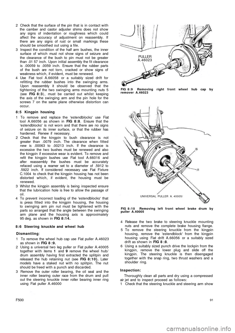
1 To remove the wheel hub cap use Fiat puller A.46023
as shown in FIG 8 : 9 .
2 Using a universal t w o leg puller or Fiat puller A.40005
together with items 1 and 9 remove the wheel hub/
drum assembly having first extracted the splitpin and
released the hub retaining nut (see FIG 8:10). Later
models have a staked nut w i t h no splitpin. The nut
should be freed with a punch and discarded.
3 Remove the outer roller bearing, the oil seal and the
inner roller bearing outer race from the drum and pull
out the steering knuckle inner roller bearing inner ring
using Fiat puller A.46000
F500PULLER
A.46023
FIG 8 : 9 Removing right front wheel hub cap by
remover A.46023
UNIVERSAL PULLER A. 40005/
FIG 8:10 Removing left front wheel brake drum by
puller A.40005
4 Release the t w o brake to steering knuckle mounting
nuts and remove the complete brake housing flange.
5 To remove the steering knuckle from the kingpin
housing, remove the 'estendblock' from the kingpin
housing using Fiat drift A.66056 or a suitably sized
drift as shown in FIG 8 : 8.
6 Using a suitably sized punch drive the lockpin from the
kingpin, remove the lower plug and slide off the
kingpin. The steering knuckle is then disengaged
together with the snap ring, two thrust washers and a
shoulder ring.
Inspection:
Thoroughly clean all parts and dry using a compressed
air jet and to inspect proceed as follows:
1 Check that the steering knuckle and steering arm show
91
Page 88 of 128
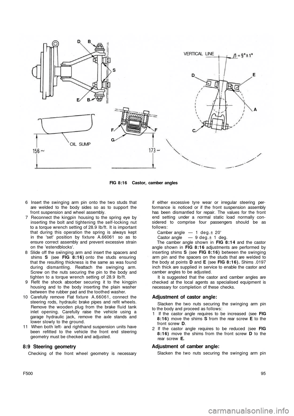
VERTICAL LINE DB
S
EB
OIL SUMPF
GF
FIG 8:16 Castor, camber angles
6 Insert the swinging arm pin onto the two studs that
are welded to the body sides so as to support the
front suspension and wheel assembly.
7 Reconnect the kingpin housing to the spring eye by
inserting the bolt and tightening the self-locking nut
to a torque wrench setting of 28.9 Ib/ft. It is important
that during this operation the spring is always kept
in the 'set' position by fixture A.66061 so as to
ensure correct assembly and prevent excessive strain
on the 'estendblocks'.
8 Slide off the swinging arm and insert the spacers and
shims S (see FIG 8:16) onto the studs ensuring
that the resulting thickness is the same as was found
during dismantling. Reattach the swinging arm.
Screw on the nuts securing the pin to the body and
tighten to a torque wrench setting of 28.9 Ib/ft.
9 Refit the shock absorber securing it to the kingpin
housing and to the body inserting the plain washer
between the rubber pad and the toothed washer.
10 Carefully remove Fiat fixture A.66061, connect the
steering rods, hydraulic brake pipes and refit wheels.
Remove the wooden plug from the brake fluid tank
inlet opening. Carefully raise the vehicle using a
garage hydraulic jack, remove the axle stands and
lower slowly to the ground.
11 When both left- and righthand suspension units have
been refitted to the vehicle the front end steering
geometry must be checked and adjusted.
8:9 Steering geometry
Checking of the front wheel geometry is necessary
95
F500
if either excessive tyre wear or irregular steering per-
formance is noticed or if the front suspension assembly
has been dismantled for repair. The values for the front
end setting under a normal static load normally con-
sidered to comprise four passengers should be as
follows:
Camber angle — 1 d e g . ± 20'
Castor angle — 9 deg.± 1 deg.
The camber angle shown in FIG 8:14 and the castor
angle shown in FIG 8 : 1 6 adjustments are performed by
inserting shims S (see FIG 8 : 1 6 ) between the swinging
arm pin and the spacers on the studs that are welded to
the body at points D and E (see FIG 8:16). Shims .0197
inch thick are supplied in service to enable the castor and
camber angles to be adjusted.
It is suggested that the castor and camber angles are
checked at the local agents as specialised equipment is
necessary for completion of these checks.
Adjustment of castor angle:
Slacken the t w o nuts securing the swinging arm pin
to the body and proceed as follows:
1 If the castor angle requires to be increased (see FIG
8:16) move the shims S from the rear screw E to the
front screw D.
2 If the castor angle requires to be reduced (see FIG
8:16) move the shims from the front screw D to the
rear screw E.
Adjustment of camber angle:
Slacken the t w o nuts securing the swinging arm pin DE
A
C
Page 89 of 128
to the body and proceed as follows:
1 If the camber angle requires to be increased (see FIG
8:16) add the same number of shims S on both
screws D and E.
2 If the camber angle requires to be reduced (see FIG
8:16) remove the same number of shims from both
screws D and E.
The addition or removal of shims at the t w o points D
and E permits camber adjustment to be made without
any disturbing of the castor angle.
8:10 Modifications
Checking and adjusting castor and camber angles:
When checking the castor and camber angle the
static loading should be such that the distance between
the semi-elliptic spring mountings G (see FIG 8:16)
and the floor level to be approximately 6.81 inches, also a
distance between the lowermost portion of the sump and
the floor level of approximately 6.14 inch for the Model
500D. For the 500 Station Wagon version the distance
between centre rear bracket for jacking-up the vehicle
and the floor level should be approximately 8.90 inches.
All other front wheel alignment specifications are the
same as for the remaining 500 saloon models.
8:11 Fault diagnosis
(a) Wheel bounce
1 Tyre casing faulty
2 Uneven tyre pressures
3 Wheels out of balance
4 Semi-elliptic mounting spring worn5 Weak or seized shock absorber
6 Wheel rim or tyre misaligned
(b) Suspension noise
1 Lack of lubrication
2 Noisy or inoperative shock absorbers
3 Worn or loose wheel bearings
(c) Pull to one side
1 Low or uneven tyre pressures
2 Incorrect front wheel alignment
3 Suspension arms distorted
4 Inoperative shock absorbers
5 Brakes binding
(d) Excessive t y r e wear
1 Incorrect tyre rotation during servicing periods
2 Incorrect camber angle
3 Incorrect toe-in
4 Incorrect tyre inflation
5 Excessive play at wheel bearings
6 Wheel wobble
7 Stiff suspension arms
8 Brakes out of adjustment
(e) Wheel wobble
1 Uneven tyre pressures
2 Loose or worn wheel bearings
3 Inoperative shock absorbers
4 Loose steering knuckle or kingpin housing
5 Incorrect front wheel alignment
6 Control arm rubber bushings, or kingpin housing and
semi-elliptic spring 'estendblock' worn
96
Page 91 of 128
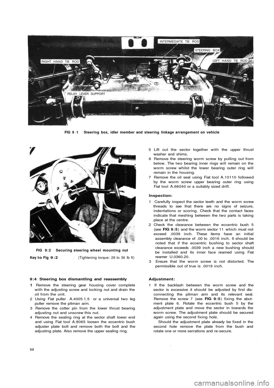
RIGHT HAND TIE ROD
RELAY LEVER SUPPORTINTERMEDIATE TIE ROD!
STEERING BOX!
LEFT HAND TIE ROD
FIG 9 :1 Steering box, idler member and steering linkage arrangement on vehicle
FIG 9 : 2 Securing steering wheel mounting nut
Key
to Fig 9:2(Tightening torque: 29 to 36 Ib ft)
9 : 4 Steering box dismantling and reassembly
1 Remove the steering gear housing cover complete
with the adjusting screw and locking nut and drain the
oil from the unit.
2 Using Fiat puller A.4005.1.5 or a universal t w o leg
puller remove the pitman arm.
3 Remove the cotter pin from the lower thrust bearing
adjusting nut and unscrew this nut.
4 Remove the sealing ring at the sector shaft lower end
and using Fiat tool A.8065 loosen the eccentric bush
adjuster plate bolt and remove both the bolt and the
adjusting plate. Also remove the upper sealing ring.
98
5 Lift out the sector together with the upper thrust
washer and shims.
6 Remove the steering worm screw by pulling out from
below. The two bearing inner rings will remain on the
worm screw whilst the lower bearing outer ring will
remain in the housing.
7 Remove the oil seal using Fiat tool A.10110 followed
by the worm screw upper bearing outer ring using
Fiat tool A.66040 or a suitably sized drift.
Inspection:
1 Carefully inspect the sector teeth and the worm screw
threads to see that there are no signs of seizure,
indentations or scoring. Check that the contact faces
indicate that meshing between the two parts is taking
place at the centre.
2 Check the clearance between the eccentric bush 5
(see FIG 9 : 5) and the worm sector 11 which must not
exceed .0039 inch. These items have an initial
assembly clearance of .00 to .0016 inch. It should be
noted that if the eccentric bushing to sector shaft
clearance exceeds .0039 inch a new bushing should
be installed and its inner face reamed using Fiat
reamer U.0360.20.
3 Ensure that the worm screw is not distorted. The
permissible out of true is .0019 inch.
Adjustment:
1 If the backlash between the worm screw and the
sector is excessive it should be adjusted by first dis-
connecting the pitman arm and its relevant seal.
Remove the screw 7 (see FIG 9 : 5) fixing the abut-
ment plate 6. Rotate the eccentric bush 5 by the
adjustment plate and move the sector in towards the
worm screw. The adjustment plate should be secured
again using the second fixing hole.
Should the adjustment plate already be fixed in the
second hole remove the plate from the bush and
rotate one or more serrations and re-secure.
Page 94 of 128
reassembling and during assembly liberally lubricated
using Fiat W90/M oil (SAE90 EP).
2 The pitman arm nut should be correctly positioned on
reassembly to the sector shaft and both are marked
with notches or a master tooth on the sector will mate
with a double tooth on the pitman arm which will
prevent incorrect reassembly.
3 The pitman arm nut must be tightened to a torque
wrench setting of 72 Ib/ft.
4 Fill the box up to the level and filler plug with SAE90 EP
gear oil.
Refitting the steering box:
To refit the steering box to the vehicle proceed as
follows:
1 Engage the w o r m screw f r o m the steering shaft by
gently manipulating the steering box.
2 Replace the steering box to body nuts and tighten to a
torque wrench setting of 14 to 18 Ib/ft.
3 Replace the t w o track rod pins in their seatings in the
pitman arm and tighten the self-locking nuts to a
torque wrench setting of 18 to 21 Ib/ft.
4 Replace the steering shaft to worm screw mounting
bolt, lock washer and nut.
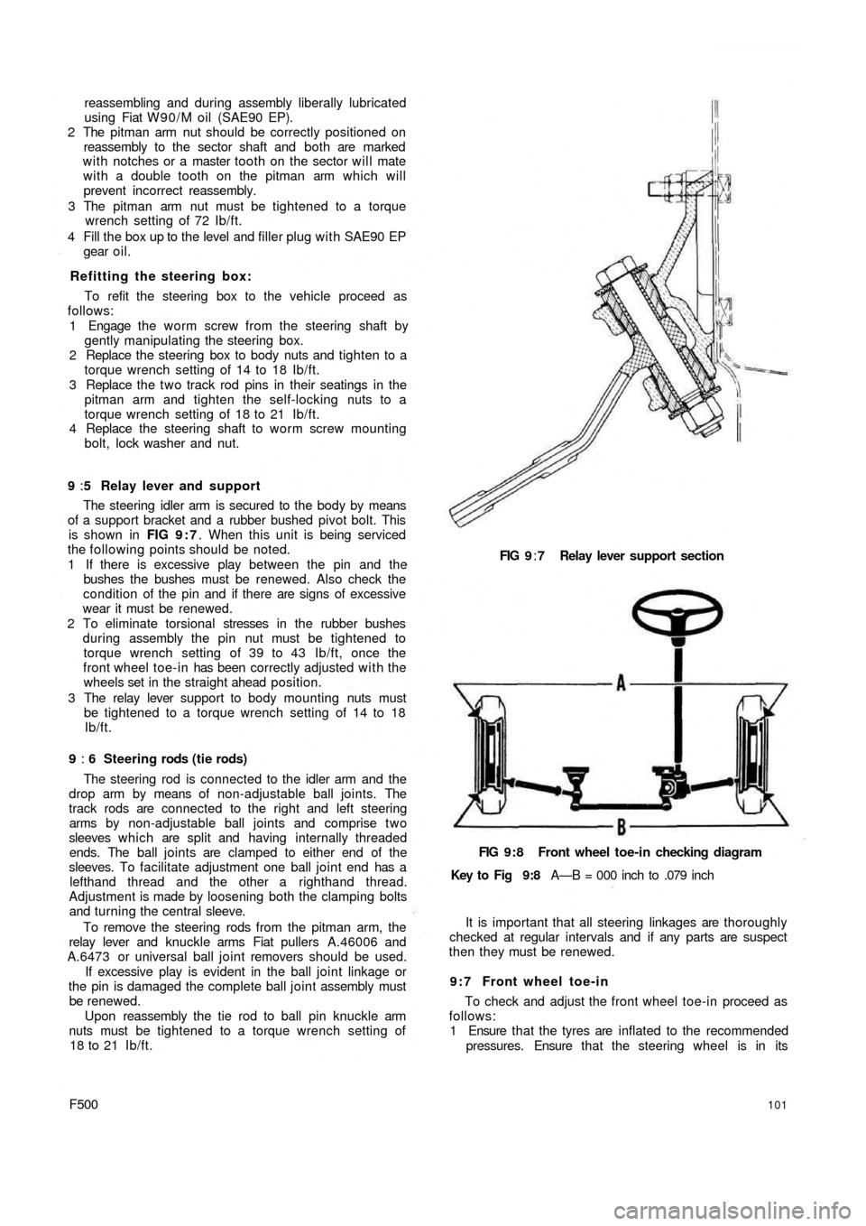
9 :5 Relay lever and support
The steering idler arm is secured to the body by means
of a support bracket and a rubber bushed pivot bolt. This
is shown in FIG 9 : 7. When this unit is being serviced
the following points should be noted.
1 If there is excessive play between the pin and the
bushes the bushes must be renewed. Also check the
condition of the pin and if there are signs of excessive
wear it must be renewed.
2 To eliminate torsional stresses in the rubber bushes
during assembly the pin nut must be tightened to
torque wrench setting of 39 to 43 Ib/ft, once the
front wheel toe-in has been correctly adjusted w i t h the
wheels set in the straight ahead position.
3 The relay lever support to body mounting nuts must
be tightened to a torque wrench setting of 14 to 18
Ib/ft.
9 : 6 Steering rods (tie rods)
The steering rod is connected to the idler arm and the
drop arm by means of non-adjustable ball joints. The
track rods are connected to the right and left steering
arms by non-adjustable ball joints and comprise t w o
sleeves which are split and having internally threaded
ends. The ball joints are clamped to either end of the
sleeves. To facilitate adjustment one ball joint end has a
lefthand thread and the other a righthand thread.
Adjustment is made by loosening both the clamping bolts
and turning the central sleeve.
To remove the steering rods from the pitman arm, the
relay lever and knuckle arms Fiat pullers A.46006 and
A.6473 or universal ball joint removers should be used.
If excessive play is evident in the ball joint linkage or
the pin is damaged the complete ball joint assembly must
be renewed.
Upon reassembly the tie rod to ball pin knuckle arm
nuts must be tightened to a torque wrench setting of
18 to 21 Ib/ft.
F500101
FIG 9:7 Relay lever support section
FIG 9:8 Front wheel toe-in checking diagram
Key to Fig 9:8 A—B = 000 inch to .079 inch
It is important that all steering linkages are thoroughly
checked at regular intervals and if any parts are suspect
then they must be renewed.
9 : 7 Front wheel toe-in
To check and adjust the front wheel toe-in proceed as
follows:
1 Ensure that the tyres are inflated to the recommended
pressures. Ensure that the steering wheel is in its
Page 95 of 128
normal straight-ahead position with the spokes
horizontal. Check that the wheels are in the straight-
ahead position.
2 Load the vehicle to static load conditions or with four
average size passengers.
3 Move the vehicle forwards for a distance of approxi-
mately six yards so that the suspension may settle
correctly.
4 The toe-in measurements should be taken at the same
point of the wheel rim. Measure at A (see FIG 9 : 8)
then back up the car to bring points A to the position B
and remeasure. The value obtained at A should be
equal to or greater than B within .0079 inch.
5 As previously described the steering rods are adjust-
able in length. Loosen the clamps and screw in or out
the adjusting sleeves and before tightening the clamp
ensure that the sleeve slot registers w i t h the clamp
joint. With the clamp fully tightened there should
always be a gap between the joint faces.
6 If the steering gear has been re-installed the correct
front wheel toe-in must be set. Then the relay lever pin
nut must be tightened to a torque wrench setting of 78
to 85 Ib/ft.
9 : 8 Fault diagnosis
(a) Front wheel shimmy
1 Incorrect tyre pressure
2 Incorrect front wheel alignment
3 Loose front wheel bearings
4 Wheels out of balance
5 Loose steering linkage connections
6 Loose steering gear or relay lever support at body
mountings
7 Incorrect fitting of steering worm to worm sector
(b) Hard steering
1 Incorrect tyre pressure
2 Incorrect front wheel alignment
3 Incorrect adjustment of steering worm to worm sector
(c) Hard turning when stationary
1 Incorrect tyre pressure
2 Incorrect adjustment of steering worm to worm sector
102
(d) Pull to one side
1 Incorrect tyre pressure
2 Incorrect front wheel alignment
3 Incorrect front wheel bearing adjustment
4 Distorted kingpin housing or swinging arms
5 Unequal brake adjustment
6 Semi-elliptic spring weak or broken
(e) Rattles
1 Loose steering linkage connections
2 Loose steering gear or relay lever support at body
mountings
3 Semi-elliptic spring weak or broken
4 Lack of lubrication
( f ) Loose steering
1 Incorrect front wheel bearing adjustment
2 Loose steering linkage connections
3 Loose steering gear mountings
4 Incorrect adjustment of steering worm to worm sector
(g) Jerky steering
1 Incorrect front wheel alignment
2 Incorrect front wheel bearing adjustment
3 Wheels out of balance
4 Loose steering linkage connections
5 Loose or incorrect fitting of worm to sector
(h) Side-to-side wander
1 Incorrect tyre pressure
2 Incorrect front wheel alignment
3 Loose steering linkage connections
4 Loose steering gear or relay lever support at body
mountings
5 Incorrect fitting of steering worm to worm sector
6 Distorted kingpin housing or swinging arm
7 Semi-elliptic spring weak or broken
(i) Tyre squeal on turns
1 Incorrect tyre pressure
2 Incorrect wheel alignment
3 Distorted kingpin housing or swinging arms
Page 103 of 128
When the pedal is applied, it moves the rear (primary)
piston to pressurise the front brakes through the rear port.
This, in turn, forces the front (secondary) piston down the
bore to pressurise the rear brake circuit through the front
port. In the event of a failure in the primary circuit, the
primary piston moves into direct contact with the second-
ary piston and full braking is still available on the rear
wheels. If a leak occurs in the rear circuit, the secondary
piston is moved to the end of the bore, sealing off the out-
let port and full braking pressure is applied to the t w o front
brakes.
With two fluid reservoirs connected to the inlets 3 and 5
the two circuits are fully independent.
The remaining components in the braking system are
similar to those used in the earlier single circuit layout.
10:13 Fault diagnosis
(a) 'Spongy' pedal
1 Leak in t h e system
2 Worn master cylinder
3 Leaking wheel cylinders
4 Air in the system
5 Gaps between shoes and underside of linings
110
(b) Excessive pedal movement
1 Check 1 and 4 in (a)
2 Excessive lining wear
3 Very low fluid level in supply reservoir
4 Too much free movement of pedal
(c) Brakes grab or pull to one side
1 Brake backplate loose
2 Scored, cracked or distorted drum
3 High spots on drum
4 Unbalanced shoe adjustment
5 Wet or oily linings
6 Worn or loose spring fixings
7 Front suspension or rear suspension anchorages
loose
8 Worn steering connections
9 Mixed linings of different grades
10 Uneven tyre pressure
11 Broken shoe return springs
12 Seized handbrake cable
Page 114 of 128
parking position the trouble will be found in the sliding
sector which fails to open the switch D (see FIG
11 :16) . Check by removing the four motor cover
mounting screws and uncover the sliding sector. If
possible suitably bend the sector to bring it against
into contact with the rod tip of switch D.
3 If the automatic parking of the blades does not occur
when the switch lever is fully depressed to the parking
position but the motor stops when the switch is
operated the cause of the trouble is that the switch D
is not closing and consequently no current is flowing
between the terminals C and INT. This will probably
be due to dirt lodged between the movable contact
and the fixed contacts of switch D. Thoroughly wash
the components with petrol and if necessary reface
the contacts using a very fine file.
4 Should the motor unit be noisy in operation although
still operating reliably the noise is probably due to the
reduction gear operation, whereby the pinion and
worm are excessively worn or a tooth chipped. The
motor unit must be renewed as motor unit parts are
not available in service.
5 If the switch lever is pushed upwards to the 'on'
position or depressed downwards to the Parking
position and the wiper is still inoperative thoroughly
check all terminal connections for tightness and
cables for damage which if all appear to be correct the
failure of the wiper to operate indicates an internal
fault of the motor unit which
should be repaired or
renewed as necessary.
Removal and refitting the motor:
Remove the wiper arms and the electrical connections
to the motor. Dismantling is a straightforward operation
providing that as all items are removed so they are
inspected and a note made of their locations. However,
reassembly requires more care and the following
procedure should be adopted.
1 Mount the wiper unit onto the body by fully tightening
the nuts fixing the pivots onto which the arms are
fitted. Ensure t h a t the rubber sealing bushes between
the pivots and body are correctly assembled to prevent
water ingress. Slightly lubricate with glycerine.
2 Secure the mounting bracket lower edge to the body
by means of the special square bracket. It is important
not to distort the mounting bracket and ease of
assembly is ensured by elongated holes in the square
bracket. By suitable adjustment the linkages will not
be subjected to distortion or abnormal stresses during
operation.
3 Fit the motor unit to the mounting bracket tightening
the screws and reassemble the main link to the pivot
lever. Ensure t h a t the l o c k i n g of the fastener on the
pivot lever is secure so that it does not become loose
during operation.
4 Remake all the electrical connections and run the
motor for a short time whilst checking all the switch
positions including the automatic parking. It is at this
position that the wiper blades and arms are assembled
to the wiper mechanism.
5 Onto the pivots, install the shims, snap ring, wiper arm,
plain washer and lockwasher. Fully tighten the nuts
with the wiper arms in the parked position.
F500
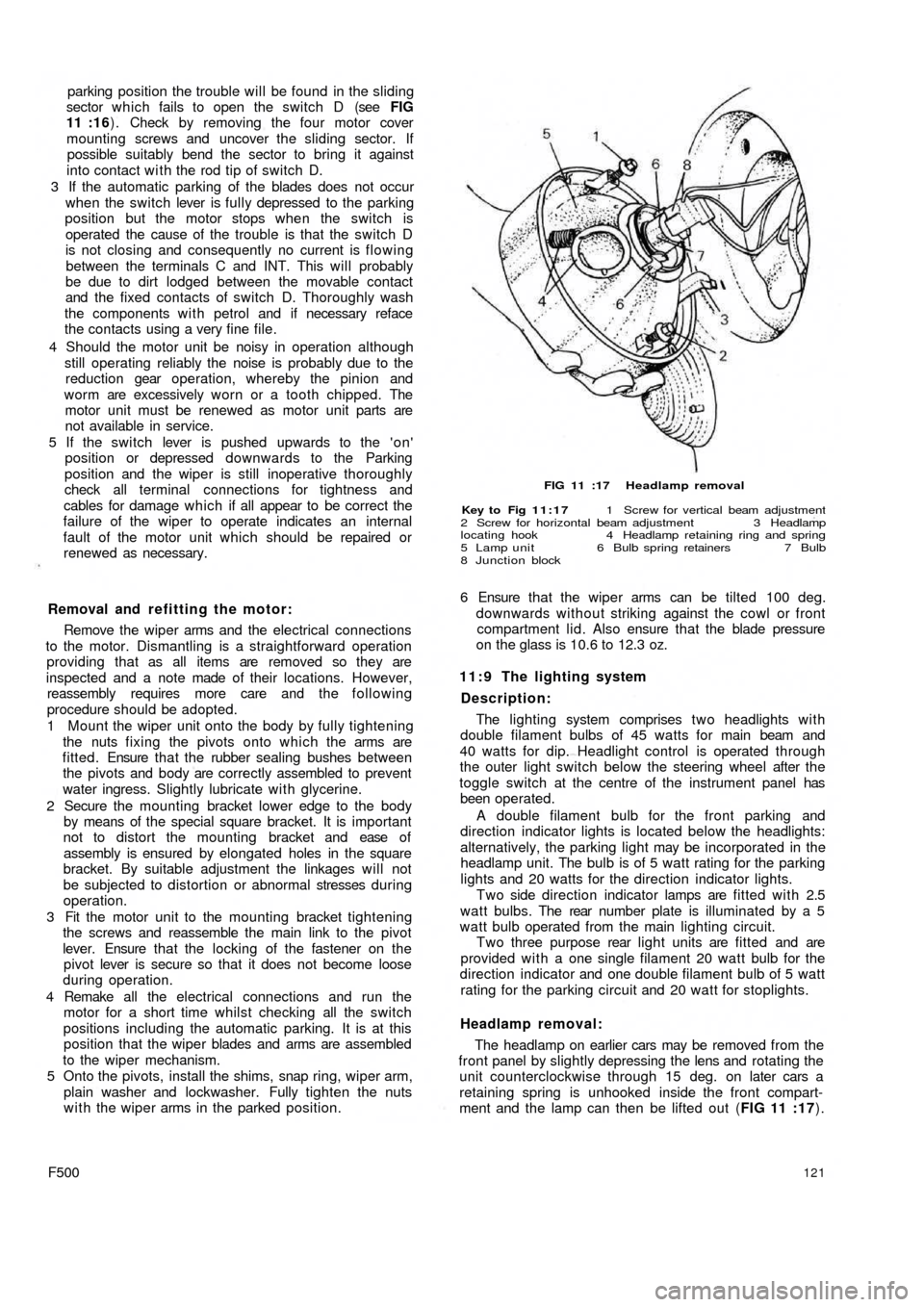
FIG 11 :17 Headlamp removal
Key to Fig 11:17 1 Screw for vertical beam adjustment
2 Screw for horizontal beam adjustment 3 Headlamp
locating hook 4 Headlamp retaining ring and spring
5 Lamp unit 6 Bulb spring retainers 7 Bulb
8 Junction block
6 Ensure that the wiper arms can be tilted 100 deg.
downwards without striking against the cowl or front
compartment lid. Also ensure that the blade pressure
on the glass is 10.6 to 12.3 oz.
1 1 : 9 The lighting system
Description:
The lighting system comprises t w o headlights with
double filament bulbs of 45 watts for main beam and
40 watts for dip. Headlight control is operated through
the outer light switch below the steering wheel after the
toggle switch at the centre of the instrument panel has
been operated.
A double filament bulb for the front parking and
direction indicator lights is located below the headlights:
alternatively, the parking light may be incorporated in the
headlamp unit. The bulb is of 5 watt rating for the parking
lights and 20 watts for the direction indicator lights.
Two side direction indicator lamps are fitted with 2.5
w a t t b u l b s . The rear number plate is illuminated by a 5
watt bulb operated from the main lighting circuit.
Two three purpose rear light units are fitted and are
provided with a one single filament 20 watt bulb for the
direction indicator and one double filament bulb of 5 watt
rating for the parking circuit and 20 watt for stoplights.
Headlamp removal:
The headlamp on earlier cars may be removed from the
front panel by slightly depressing the lens and rotating the
unit counterclockwise through 15 deg. on later cars a
retaining spring is unhooked inside the front compart-
ment and the lamp can then be lifted out (FIG 11 :17).
121
Page 116 of 128
Lamp brilliance varies w i t h the speed of t h e car:
Check the condition of the battery. Examine the battery
connections. Make sure they are tight and renew faulty
cables.
11:10 Panel and warning lights:
All the gauges are clustered in a single instrument
mounted on the dashboard above the steering column.
Incorporated in this cluster is the parking light pilot light,
generator charge indicator, fuel reserve supply indicator,
low oil pressure indicator, and the speedometer w i t h
mileage recorder.
The parking lamp indicator glows green when the
ignition lock switch key is in either position 1 or 2 once
the toggle switch on the instrument panel has been
operated.
The generator charge indicator shows red only when
the ignition is turned on. It should be extinguished when
the generator output is sufficient for battery charge
(12.6 ± 0.2 volts) with the engine running at a speed
of 1100 rev/min and the headlights switched off.
The fuel reserve supply indicator shows red only when
the ignition is turned on and the amount of fuel in the
petrol tank has dropped to approximately .8 to 1.1
Imp. gallons.
The low oil pressure indicator shows red only when the
ignition is turned on and should be extinguished when
the oil pressure reaches 7.1 to 21.3 Ib/sq in, and opens
the sending unit contacts. Once the engine is at normal
operating temperature but at a speed below 1000 rev/
min the indicator might light up even the pressure is under
control and with normal operation.
All the bulbs fitted to the above described units are of
the tubular 2.5W type and to renew a bulb extract the
bulb holder from the rear of t h e instrument cluster and
release the bulb which is attached by a normal bayonet
coupling.
Fuel reserve supply indicator sender u n i t:
The fuel reserve supply indicator should be checked for
correct indication by allowing the fuel tank to empty and
then inserting .8 to 1.1 Imp. gallons at which stage the
light should extinguish. Any failure to do so should be
checked as follows:
1 Ensure that the indicator bulb operates correctly.
2 Check for complete circuit between the sender unit and
the indicator bulb.
3 If the sender unit float bracket is distorted the bulb
will
indicate a reserve supply of fuel greater or smaller than
specified. The bracket should be adjusted to give
correct indication of fuel level.
4 The sender unit could have been inadvertantly
damaged in which case the unit must be renewed.
11 :11 The horn
The horn circuit comprises the horn, push button at the
centre of the steering wheel and normal earth return
electrical circuit through the car body. One terminal is
connected to the battery whilst the other to the push
button on the steering wheel which when the button is
depressed the circuit will be closed so causing the horn
to operate.
F500
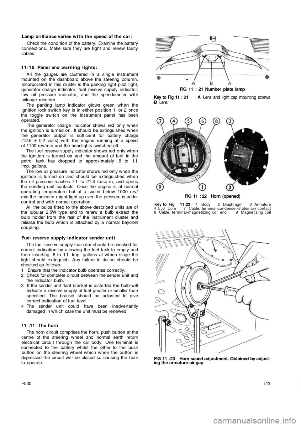
FIG 11 : 21 Number plate lamp
Key to Fig 11 : 21 A Lens and light cap mounting screws
B Lens
FIG 11 : 22 Horn (opened)
Key to Fig 11:22 1 Body 2 Diaphragm 3 Armature
4,5,6 Core 7 Cable: terminal-condenser-stationary contact
8 Cable: terminal-magnetizing coil end 9 Magnetizing coil
FIG 11 :23 Horn sound adjustment. Obtained by adjust-
ing the armature air gap
123
Page 117 of 128
Before removing an apparently faulty horn check the
wiring and connections. Check that the mounting bolts
are tight and that the horn does not foul any adjacent part.
Removal and installation:
This is a straightforward operation and the only
precaution to be taken is to ensure that the rubber gasket
bonded to the horn body does not become detached. If
the horn is renewed, before installing the new horn bond
the rubber gasket to the new unit with adhesive in
the same position as was on the original horn unit fitted.
Should the horn fail to operate the following points
should be noted.
1 Damaged horn.
2 Broken connection between battery and horn.
3 Broken connection between horn and push button on
steering wheel
4 Damaged push button mechanism.
5 Directional signal and outer lighting changeover
switch blade contact failing to make contact with the
steering wheel hub ring contact.
6 Current lead displaced from the horn blade contact on
the directional signal and outer lighting switch.
7 Distorted or broken diaphragm in horn.
8 Connections or inner windings
broken or burnt.
9 Electro-magnet contact points dirty or excessively
worn.The contacts may be adjusted by the adjusting screw
after the points have been cleaned and refaced.
To adjust the tone of the horn use a ring spanner and
screwdriver as shown in FIG 11 :23.
It is recommended that if the horn unit operation is
unreliable a new unit should be fitted rather than the
original one repaired.
11:12 Lighting and flasher switch
Description:
The two switches provide a directional signal switch
which automatically returns to the rest position once a
turn has been negotiated and the steering wheel is
brought back to the straight-ahead position. The change
over switch controls the outer lights and the headlights
flasher. The complete unit is located under the steering
wheel on the steering column.
Switch unit removal:
1 Carefully pry off the horn push button at the steering
wheel centre using a fine blade screwdriver.
2 Disconnect the positive terminal of the battery.
3 Disconnect the plug in contact in the steering wheel
hub.
4 Unscrew the steering wheel retaining nut from the
inner column and remove the steering wheel from the
shaft.
5 Slacken the bolts securing the steering column support
to the body
6 Remove the plug in contacts from the switch unit
ensuring that their correct location is noted for re-
assembly.7 Remove the switch unit from the steering column.
124
Switch unit installation:
This is the reverse procedure to dismantling. It is
advisable after installation to check that the steering
wheel when in the straight-ahead position and the
directional signal switch lever in neutral, the reference
index on the outer face of the directional signal switch
drum is in line with the index on the steering wheel hub.
This will ensure correct sequence of operation.
11:13 Fault diagnosis
(a) Battery discharged
1 Lighting circuit shorted
2 Terminals loose or dirty
3 Generator not charging
4 Regulator or cut-out units not working properly
5 Battery internally defective
(b) Insufficient charging current
1 Loose or corroded battery terminals
2 Generator driving belt slipping
(c) Battery will not hold a charge
1 Low electrolyte level
2 Battery plates sulphated
3 Electrolyte leakage from cracked casing or top sealing
compound
4 Plate separators ineffective
(d) Battery overcharged
1 Voltage regulator needs adjusting
(e) Generator output low or nil
1 Belt broken or slipping
2 Regulator unit out of adjustment
3 Worn bearings, loose pole pieces
4 Commutator worn, burned or shorted
5 Armature shaft bent or worn
6 Insulation proud between commutator segments
7 Brushes sticking, springs weak or broken
8 Field coil wires shorted, broken or burned
( f ) Starter motor lacks power or will not operate
1 Battery discharged, loose cable connections
2 Starter pinion jammed in mesh with flywheel gear
3 Starter switch faulty
4 Brushes worn or sticking, heads detached or shorting
5 Commutator dirty or worn
6 Starter shaft bent
7 Engine abnormally stiff
(g) Starter motor inoperative
1 Check 1 in (f)
2 Armature or field coils faulty