all grease points FIAT 500 1969 1.G Workshop Manual
[x] Cancel search | Manufacturer: FIAT, Model Year: 1969, Model line: 500, Model: FIAT 500 1969 1.GPages: 128, PDF Size: 9.01 MB
Page 41 of 128
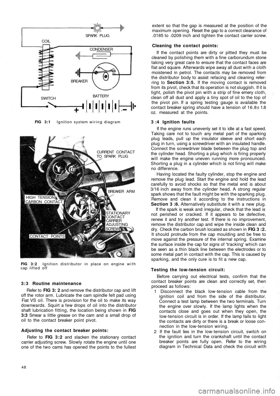
FIG 3 : 1 Ignition system wiring diagram
BATTERY
SWITCHBREAKER COIL
SPARK PLUG
CONDENSER
FIG 3 : 2 Ignition distributor in place on engine with
cap lifted offCURRENT CONTACT
TO SPARK PLUG
BREAKER A R M
STATIONARY
CONTACT
CARRIER
ADJUSTING
SCREW
CONTACT POINTS HIGH TENSION)
CARBON CONTACT
3 : 3 Routine maintenance
Refer to FIG 3: 2 and remove the distributor cap and lift
off the rotor arm. Lubricate the cam spindle felt pad using
Fiat VS oil. There is provision for the oil to make its way
downwards. Squirt a few drops of oil into the distributor
shaft lubrication fitting, the location being shown in FIG
3:3 Smear a little grease on the cam and a small drop of
oil to the contact breaker point pivot.
Adjusting the contact breaker points:
Refer to FIG 3 : 2 and slacken the stationary contact
carrier adjusting screw. Slowly rotate the engine until one
one of the t w o cams has opened the points to the fullest
48
extent so that the gap is measured at the position of the
maximum opening. Reset the gap to a correct clearance of
.0185 to .0209 inch and tighten the contact carrier screw.
Cleaning the contact points:
If the contact points are dirty or pitted they must be
cleaned by polishing them with a fine carborundum stone
taking very great care to ensure that the contact faces are
flat and square. Afterwards wipe away all dust with a cloth
moistened in petrol. The contacts may be removed from
the distributor body to assist refacing and cleaning refer-
ring to Section 3:5. If the moving contact is removed
from its pivot, check that its operation is not sluggish. If it is
tight, polish the pivot pin with a strip of fine emery cloth,
clean off all dust and apply a tiny spot of oil to the top of
the pivot pin. If a spring testing gauge is available the
contact breaker spring should have a tension of 16.8± 1.8
oz. measured at the points.
3 :4 Ignition faults
If the engine runs unevenly set it to idle at a fast speed.
Taking care not to touch any metal part of the sparking
plug leads, pull up the insulator sleeve and short each
plug in turn, using a screwdriver with an insulated handle.
Connect the screwdriver blade between the plug top and
the cylinder head. Shorting a plug which is firing properly
will make the engine uneven running more pronounced.
Shorting a plug in a cylinder which is not firing will make
no difference.
Having located the
faulty cylinder, stop the engine and
remove the plug lead. Start the engine and hold the lead
carefully to avoid shocks so that the metal end is about
3/16 inch away from the cylinder head. A strong regular
spark shows that the fault might be with the sparking plug.
Remove and clean it according to the instructions in
Section 3 :8. Alternatively substitute it with a new plug.
If the spark is weak and irregular, check that the lead is
not perished or cracked. If it appears to be defective,
renew it and try another test. If there is no improvement,
remove the distributor cap and wipe the inside clean and
dry. Check the carbon brush located as shown in FIG 3 : 2 .
It should protrude from the cap moulding and be free to
move against the pressure of the internal spring. Examine
the surface inside the cap for signs of 'tracking' which can
be seen as a thin black line between the electrodes or to
some metal part in contact with the cap. This is caused by
sparking, and the only cure is to fit a new cap.
Testing the low-tension circuit:
Before carrying out electrical tests, confirm that the
contact breaker points are clean and correctly set, then
proceed as follows:
1 Disconnect the black low-tension cable from the
ignition coil and from the side of the distributor.
Connect a test lamp between the t w o terminals. Turn
the engine over slowly. If the lamp lights when the
contacts close and goes out when they open, the
low-tension circuit is in order. If the lamp fails to light
the contacts are dirty or there is a break or loose con-
nection in the low-tension wiring.
2 If the fault lies in the
low-tension circuit, switch on
the ignition and turn the crankshaft until the contact
breaker points are fully open. Refer to the wiring
diagram in Technical Data and check the circuit with
Page 44 of 128
indicates the condition inside the combustion chamber
and may be used as a guide to engine tuning.
Before the spark plugs are removed b l o w away any
loose dirt from the plug recesses using a compressed air
jet or tyre pump. Store the plugs in the order of removal
ready for inspection.
Examine the gaskets and if they are about half their
thickness they may be used again otherwise they must be
replaced.
Inspect the electrode end of the plugs and note the
type and colour of the deposit. Normally it should be
powdery and range from b r o w n to a greyish tan in colour.
There will also be slight wear of the electrodes and the
general effect described is one which comes from mixed
periods of high-speed and low-speed driving. Cleaning
and resetting the gap is all that will be necessary.
If the deposits are white or yellowish they indicate long
periods of constant-speed driving or much low-speed
city driving. Again, the treatment is straightforward.
Dry, black, fluffy deposits are usually the result of
running with too rich a mixture. Incomplete combustion
of the petrol air charge may also be a cause and this might
be traced to a defect in the ignition system or excessive
idling.
Overheated sparking plugs have a white blistered look
about the centre electrode and the side electrode may be
badly eroded. This may be caused by poor cooling, wrong
ignition timing or sustained high speeds under heavy load.
To clean the sparking plugs effectively they should be
cleaned using an abrasive blasting machine and tested
under pressure once the electrodes have been reset. File
these until they are clean, bright and the faces parallel and
set the gap to .019 to .023 inch. Do not try to bend the
centre electrode.
Before replacing the plugs use a wire brush to clean the
threads taking care that the electrodes are not touched.
Thoroughly clean the spark plug in petrol, and dry using a
compressed air jet or a tyre pump. If difficulty is found in
screwing the plugs into the cylinder head by hand run a
tap d o w n the threads to clear away any carbon. If a tap is
not available use an old sparking plug with crosscuts d o w nthe threads. Finally tighten the plugs to a torque wrench
setting of 18 to 21 Ib ft.
Sparking plug leads:
The spark plug leads and the lead from the coil to the
distributor cap must be regularly checked for cracking of
the insulation and also correct seating in the distributor
cap and coil top. It is recommended that silicone grease is
smeared around the sockets before the leads are replaced
to ensure no moisture may enter causing difficult starting.
3 : 9 The distributor driving spindle (sedan and
sports engine)
If for any reason, the driving spindle has been removed
from its housing in the crankcase, it must be correctly
meshed w i t h the camshaft gear otherwise it
will be impos-
sible to set the ignition timing.
3:10 Fault diagnosis
(a) Engine w i l l not fire
1 Battery discharged
2 Distributor contact points dirty, pitted or maladjusted
3 Distributor cap dirty, cracked or tracking
4 Carbon brush inside distributor cap not touching rotor
5 Faulty cable or loose connection in low-tension circuit
6 Distributor rotor arm cracked
7 Faulty coil
8 Broken contact breaker spring
9 Contact points stuck open
(b) Engine misfires
1 Check 2, 3, 4, and 7 in (a)
2 Weak contact breaker spring
3 High-tension plug and coil leads cracked or perished
4 Sparking plug(s) loose
5 Sparking plug insulation cracked
6 Sparking plug gap incorrectly set
7 Ignition timing too far advanced
Page 107 of 128
1
791011 8 234
11
10
16,15
14 13
1265
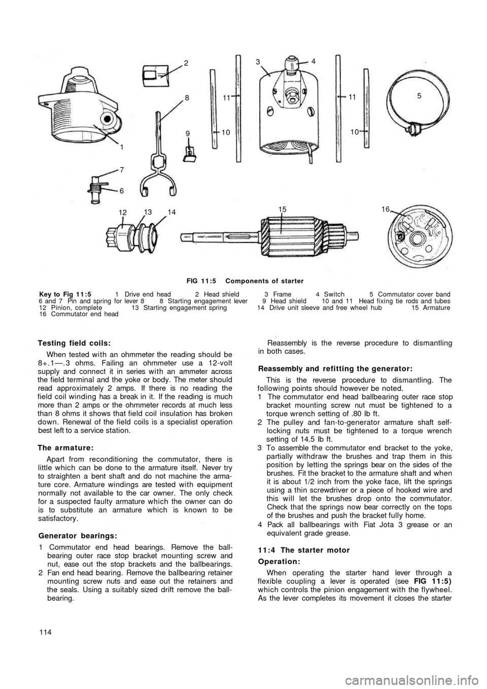
FIG 11:5 Components of starter
Key to Fig 11:5 1 Drive end head 2 Head shield 3 Frame 4 Switch 5 Commutator cover band
6 and 7 Pin and spring for lever 8 8 Starting engagement lever 9 Head shield 10 and 11 Head fixing tie rods and tubes
12 Pinion, complete 13 Starting engagement spring 14 Drive unit sleeve and free wheel hub 15 Armature
16 Commutator end head
Testing field coils:
When tested w i t h an ohmmeter the reading should be
8+.1—.3 ohms. Failing an ohmmeter use a 12-volt
supply and connect it in series w i t h an ammeter across
the field terminal and the yoke or body. The meter should
read approximately 2 amps. If there is no reading the
field coil winding has a break in it. If the reading is much
more than 2 amps or the ohmmeter records at much less
than 8 ohms it shows that field coil insulation has broken
down. Renewal of the field coils is a specialist operation
best left to a service station.
The armature:
Apart from reconditioning the commutator, there is
little which can be done to the armature itself. Never try
to straighten a bent shaft and do not machine the arma-
ture core. Armature windings are tested w i t h equipment
normally not available to the car owner. The only check
for a suspected faulty armature which the owner can do
is to substitute an armature which is known to be
satisfactory.
Generator bearings:
1 Commutator end head bearings. Remove the ball-
bearing outer race stop bracket mounting screw and
nut, ease o u t t h e stop brackets and the ballbearings.
2 Fan end head bearing. Remove the ballbearing retainer
mounting screw nuts and ease o u t t h e retainers and
the seals. Using a suitably sized drift remove the ball-
bearing.
114Reassembly is the reverse procedure to dismantling
in both cases.
Reassembly and refitting the generator:
This is the reverse procedure to dismantling. The
following points should however be noted.
1 The commutator end head ballbearing outer race stop
bracket mounting screw nut must be tightened to a
torque wrench setting of .80 Ib ft.
2 The pulley and fan-to-generator armature shaft self-
locking nuts must be tightened to a torque wrench
setting of 14.5 Ib ft.
3 To assemble the commutator end bracket to the yoke,
partially withdraw the brushes and trap them in this
position by letting the springs bear on the sides of the
brushes. Fit the bracket to the armature shaft and when
it is about 1/2 inch from the yoke face, lift the springs
using a thin screwdriver or a piece of hooked wire and
this will let the brushes drop onto the commutator.
Check that the springs now bear correctly on the tops
of the brushes and push the bracket fully home.
4 Pack all ballbearings with Fiat Jota 3 grease or an
equivalent grade grease.
11:4 The starter motor
Operation:
When operating the starter hand lever through a
flexible coupling a lever is operated (see FIG 11:5)
which controls the pinion engagement with the flywheel.
As the lever completes its movement it closes the starter