fuse box FIAT 500 1969 1.G Workshop Manual
[x] Cancel search | Manufacturer: FIAT, Model Year: 1969, Model line: 500, Model: FIAT 500 1969 1.GPages: 128, PDF Size: 9.01 MB
Page 42 of 128

a n 0—20 v o ltmeter. If the circuit is in order the meter
should read approximately 12-volts.
3 Battery to fuse box terminal 30. Connect the volt-
meter between the terminal 30 and earth. No reading
indicates a faulty cable or loose connection.
4 Fuse box. Connect the voltmeter between the other
auxiliary terminal 30 and earth. No reading indicates a
broken or loose connection.
5 Fuse box auxiliary terminal 30 to terminal
number 30 on ignition switch. Connect the meter
between terminal number 30 on the ignition switch
and earth. No reading indicates a damaged cable or
loose connection.
6 Ignition switch. Connect the meter between termi-
nal 15/54 and earth. Switch onto the ignition position,
when no reading indicates a fault in the switch.
7 Ignition switch to low-tension cable connection
on the coil (blue cable). Connect the meter
between ignition coil terminal (blue cable) and earth.
No reading indicates a damaged cable or loose con-
nection.
8 Ignition coil. Disconnect the black low-tension cable
connecting the coil to the distributor side terminal at
the coil and connect the meter between this terminal
and earth. No reading indicates a fault in the primary
winding of the coil and a replacement coil must be
fitted. If the reading is correct remake the connections
to the coil.
9 Ignition coil to distributor. Disconnect the thin
black low-tension cable at the side of the distributor
and connect the meter between the end of this cable
and earth. No reading indicates a damaged cable or
loose connections.
10 Contact breaker and capacitor. Connect the
meter across the contact breaker points. No reading
indicates a faulty capacitor.
Capacitor:
The best method of testing a capacitor (condenser) is
by substitution. Disconnect the original capacitor and
connect a new one between the low-tension terminal on
the side of the distributor and earth.
If a new capacitor is needed, fit a new one complete
w i t h bracket, but if necessary unsolder the original bracket
and solder it onto the new capacitor using as little heat as
possible. Capacitor capacity is .15-.20 microfarads.
3 : 5 Removing and dismantling distributor (sedan
and sports)
To remove the distributor proceed as follows:
1 Rotate the engine slowly until the distributor rotor arm
is opposite the brass segment in the distributor cap
connected to No. 1 plug lead. This will provide a datum
for replacement.
2 Disconnect the cable from the low-tension terminal on
the side of the distributor body. Mark position of distri-
butor on support. Release the distributor retaining nut
and washer from the underside of the top flange of the
distributor support and carefully lift away the dis-
tributor.
3 Pull off the rotor arm. Remove the insulated terminal
assembly from the side of distributor body. Release the
contact breaker carrier plate retaining screws and con-
denser flange screw from the outside of the distributor
F50049 body. Carefully lift out the contact breaker plate
assembly.
4 Before further dismantling note the relative positions of
the driving dog and the rotor arm driving slot at the top
of the distributor cam spindle. The driving dog is offset
and can only engage its driving spindle in one position.
Then when the cam assembly is fitted to the centrifugal
weights during reassembly the timing is not 180 deg.
out.
5 Take out the cam lubrication felt pad recessed in the
rotor arm housing on the end of the cam spindle.
Remove the retaining screw, carefully disengage the
springs and lift out the cam spindle. It should be noted
that there is a small retaining ball and spring located in a
drilling nearly at the top of the drive shaft spindle.
Carefully lift away the weights.
6 Thoroughly clean all parts and inspect for excessive
wear. The distributor cap must not be cracked or show
signs of tracking. The cap terminals, rotor and contact
breaker points can be cleaned with a very fine file.
Emerypaper must not be used. If the clearance between
the rotor and distributor cap segments exceeds .0118
inch both the rotor and distributor cap must be replaced.
Inspect the contact breaker arm rubbing block for exces-
sive wear and also the points for wear so that if the gap
exceeds the last setting limit of .0209 inch and adjust-
ment through the stationary contact carrier screw is no
longer possible (see FIG 3 : 2) , the contact breaker set
must be renewed.
If the distributor drive shaft side or vertical movement is
excessive the distributor must be renewed.
Weak centri-
fugal weight springs or damaged weights must be
renewed using original Fiat spares otherwise the auto-
matic ignition advance characteristics could be altered.
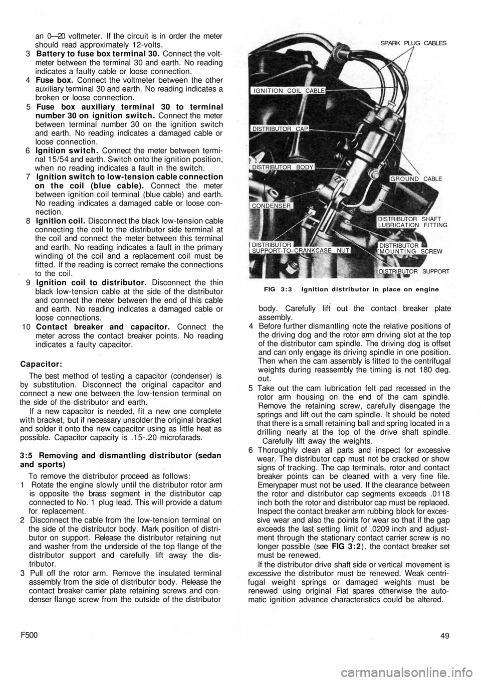
FIG 3 : 3 Ignition distributor in place on engine SPARK PLUG CABLES
IGNITION COIL CABLE!
DISTRIBUTOR CAP
DISTRIBUTOR BODY
GROUND CABLE
CONDENSER
DISTRIBUTOR SHAFT
LUBRICATION FITTING
DISTRIBUTORSUPPORT-TO--CRANKCASE NUT
[MOUNTING SCREWDISTRIBUTOR
DISTRIBUTOR SUPPORT
Page 104 of 128

CHAPTER 11
THE ELECTRICAL EQUIPMENT
11:1 Description
11:2 Battery
11:3 The generator
11:4 The starter
11:5 The control box
1 1 : 6 Fuses
1 1 : 7 Flasher unit
11:1 Description
All models covered by this manual have 12 volts
electrical systems in which the negative battery terminal
is earthed. There are three units in the regulator box to
control the charging circuit; a cut-out, a current regulator
and a voltage regulator. These are adjustable but it must
be stressed that accurate moving coil meters are required
when checking or altering the settings. Cheap and
unreliable instruments will make accurate adjustments
impossible.
There are wiring diagrams in Technical Data at the end
of this manual to enable those with electrical experience
to trace and correct wiring faults.
For t h e U.K. Market the headlamps are of the double
filament dipping renewable bulb type with adjustments
for individual beam settings.
The battery is located in the front compartment
forward of the petrol tank and the fuses to the rear o f the
petrol tank.
Detailed instructions for servicing the electrical equip-
ment will be found in this chapter, but it must be pointed
out that it is not sensible to try to repair that which is
seriously defective, electrically or mechanically. Such
equipment should be replaced by new units which can
be obtained on an exchange basis.
F500111
11 :8 Windscreen wipers
1 1 : 9 The lighting system
11:10 Panel and warning lights
11:11 The horn
11:12 Lighting and flasher switch
1 1 : 1 3 Fault diagnosis
11.2 The battery
This of the 12-volt lead/acid type and has to meet
heavy demands for current particularly in the winter. To
maintain the performance of the battery at its maximum
it is essential to carry out the following operations.
Keep the top of the battery and surrounding parts dry
and clean, as dampness can cause leakage between the
securing clamps and the battery terminals. Clean off any
corrosion from the metal parts of the battery mounting
with diluted ammonia and paint them with an anti-
sulphuric paint. If the terminal posts are corroded,
remove the cables and clean w i t h diluted ammonia.
Smear the posts w i t h petroleum jelly before remaking the
connections and fit the terminals securely. High electrical
resistance due to corrosion at the terminal posts is often
responsible for lack of sufficient current to operate the
starter motor.
Ensure t h a t the filler plugs are in good condition and
show no signs of cracks. This may cause leakage of
electrolyte and consequent corrosion. Test the condition
of the cells after topping-up the electrolyte level with
distilled water to just above the tops of the separators as
shown in FIG 11 :2 . Never add neat acid. If it is
necessary to make a new electrolyte due to loss by
spillage add sulphuric acid to the
distilled water.
It is highly dangerous to add water to acid.