stop start FIAT 500 1973 1.G Workshop Manual
[x] Cancel search | Manufacturer: FIAT, Model Year: 1973, Model line: 500, Model: FIAT 500 1973 1.GPages: 128, PDF Size: 9.01 MB
Page 6 of 128
The interior of the car can be heated by the engine
warmed air being ducted into the front compartment and
controlled by a lever on the heating system tunnel.
Engine ignition is by a battery, ignition coil and distribu-
tor which is driven by a gear on the camshaft. The engine
is started by an electric starter motor which is mounted on
the gearbox casing and is controlled by a lever located
behind the gearchange lever.
The complete power unit is mounted by a spring support
at the centre of the rear b o d y crossmember and by t w o
rubber pads mounted laterally to the gearbox.
1 :2 Engine removal (sedan—all versions)
To remove the engine from the car proceed as follows:
Raise t h e rear of t h e car and place on firmly based
stands placed under suitable brackets on the underside
of the body.
Disconnect the battery positive terminal clamp from the
battery terminal post. Release the clip securing the main
petrol pipe to the tank sender unit and ease t h e pipe
from the unit. Drain the oil from the engine sump into
a suitably sized container.
D i s c o n n e c t t h e rear number plate light wire (see
FIG 1 : 6) . Release t h e engine compartment lid check
strap from its slot and separate the lid from the body by
sliding the hinge apart.
Remove the cables attached to the ignition coil, also
to the generator and the starter motor. Remove the
starter motor control tie rod.
Release the oil pressure
indicator cable, the main petrol pipeline at the pump,
the accelerator and starting device controls.
Remove the t w o hoses of the heating and cooling
system which are the input hose to the blower and the
hose for the car heating system. Release and lift out the
engine apron. Remove the starter motor mounting bolts
and carefully lift away the motor.
Using a garage hydraulic jack with suitable cradle (see
FIG 1 : 7) or a rope sling relieve the engine weight
from its mountings. Remove the nuts securing the
gearbox to the engine and the flywheel protection
apron.
Remove the bolts fixing the elastic support to the cross-
member. Remove the rear crossmember mounting nuts
noting that the engine earth cable is held by one
mounting nut and lift away the crossmember.
Carefully ease t h e engine away from the gearbox
ensuring that there is no strain placed on the clutch
shaft. Lower the engine to the floor taking care that no
weight is allowed on any of the attachments. 1
2
3
4
5
6
7
8
1 :3 Engine removal (station wagon)
To remove the engine from the station wagon proceed
as follows:
1 Raise t h e rear of the vehicle and place on firmly based
stands placed under suitable brackets on the underside
of the body.
2 Disconnect the battery positive terminal clamp from
the battery terminal post. Release the clip securing the
main petrol pipe to the tank sender unit and ease the
pipe from the unit. Drain the oil from the engine sump
into a clean dry container of suitable size.
3 H o l d t h e rear door open and secure using string to stop
it swinging to the closed position. Secure the luggage
compartment floor panel in its upright position.
F50013 4 Remove the cables attached to the ignition coil, also
to the generator and starter motor. Remove the starter
motor control tie rod. Release the o i l pressure indicator
cable, the main petrol pipeline at the pump, the accele-
rator and starting device controls. Disconnect the air
filter housing.
5 Remove the hose connecting the car heating system
to the engine cowling. Disconnect the clip holding the
air pipe to the blower and carefully disconnect the pipe
from the blower cowling. Remove the starter motor
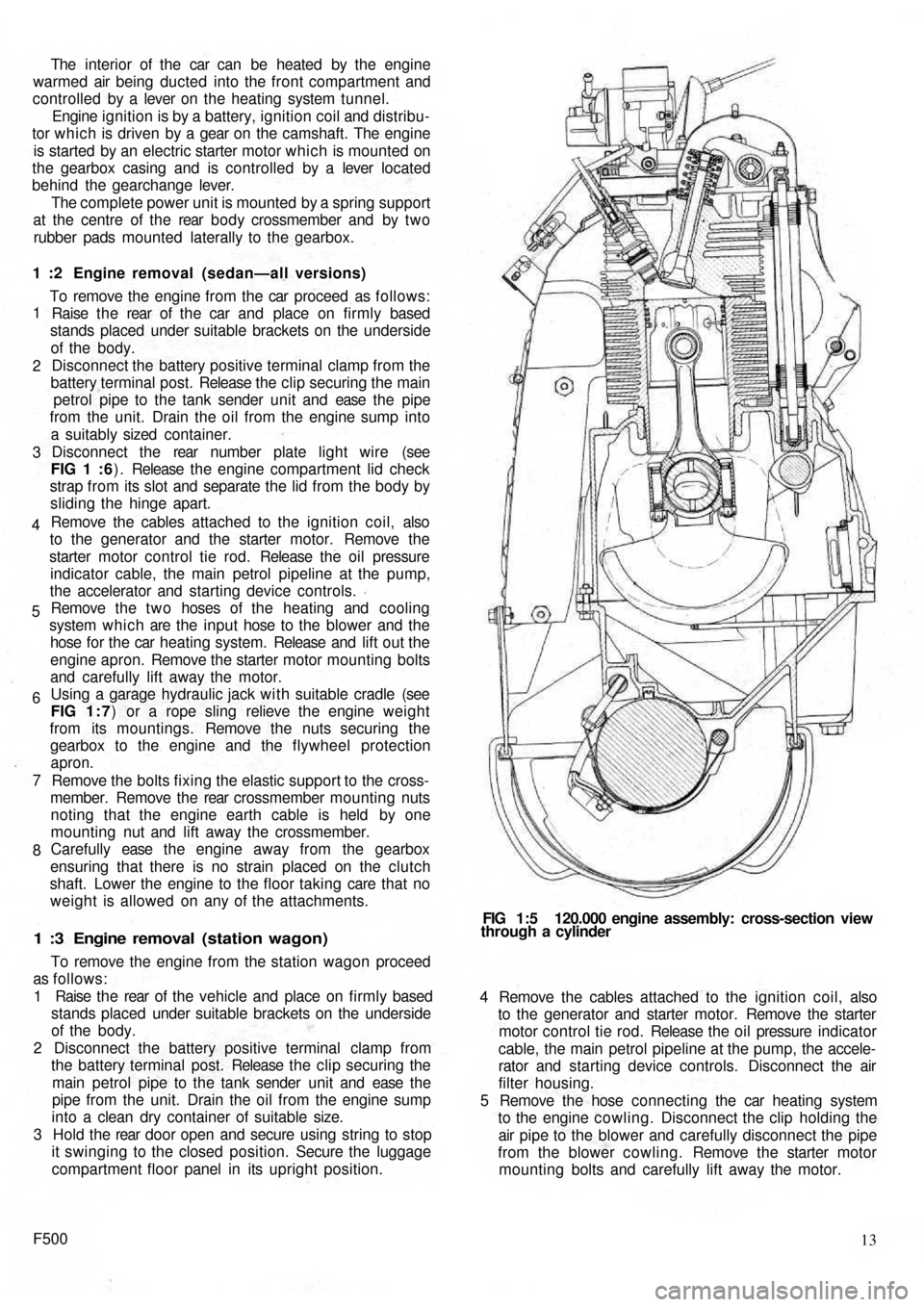
mounting bolts and carefully lift away the motor. FIG 1:5 120.000 engine assembly: cross-section view
through a cylinder
Page 41 of 128
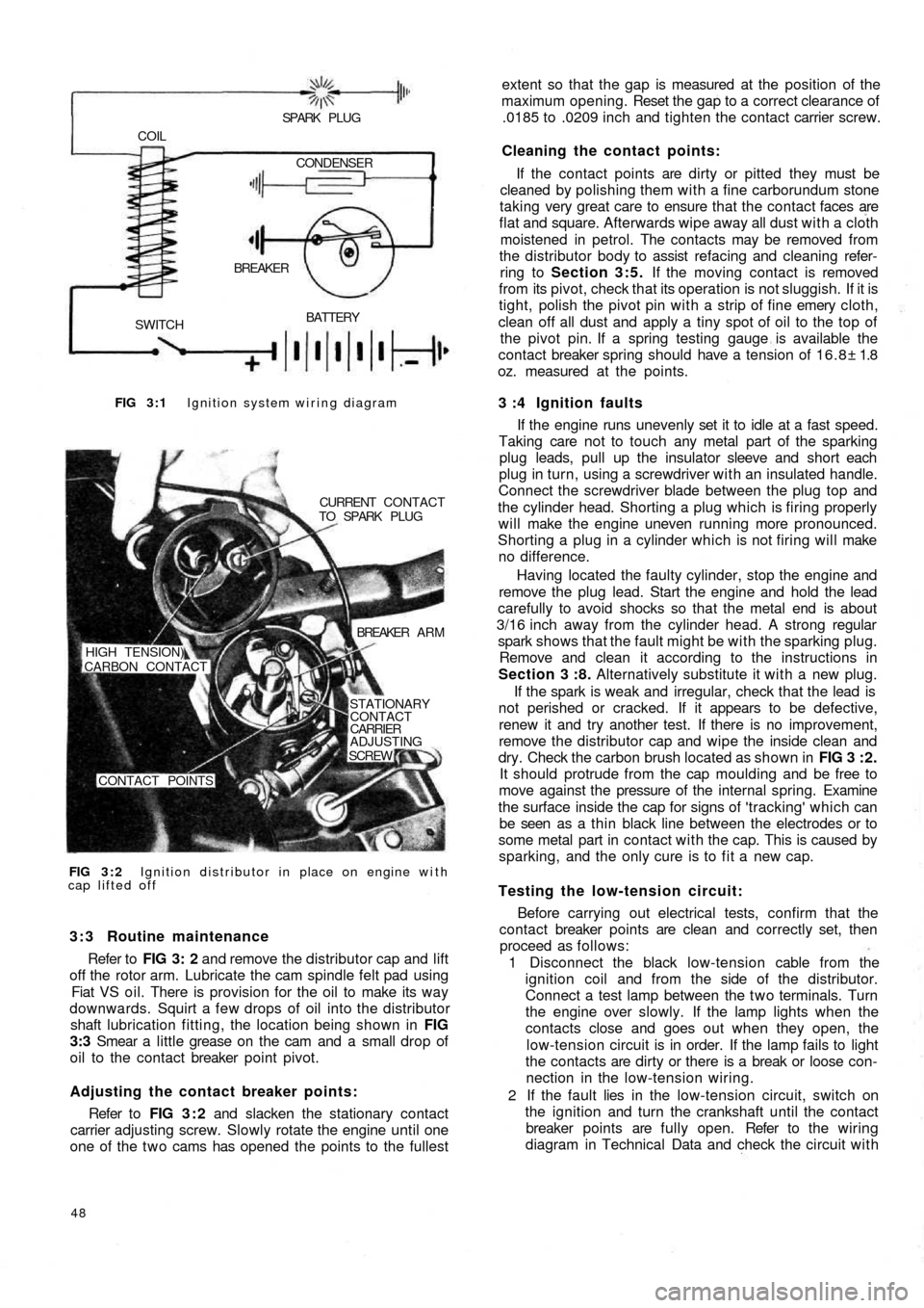
FIG 3 : 1 Ignition system wiring diagram
BATTERY
SWITCHBREAKER COIL
SPARK PLUG
CONDENSER
FIG 3 : 2 Ignition distributor in place on engine with
cap lifted offCURRENT CONTACT
TO SPARK PLUG
BREAKER A R M
STATIONARY
CONTACT
CARRIER
ADJUSTING
SCREW
CONTACT POINTS HIGH TENSION)
CARBON CONTACT
3 : 3 Routine maintenance
Refer to FIG 3: 2 and remove the distributor cap and lift
off the rotor arm. Lubricate the cam spindle felt pad using
Fiat VS oil. There is provision for the oil to make its way
downwards. Squirt a few drops of oil into the distributor
shaft lubrication fitting, the location being shown in FIG
3:3 Smear a little grease on the cam and a small drop of
oil to the contact breaker point pivot.
Adjusting the contact breaker points:
Refer to FIG 3 : 2 and slacken the stationary contact
carrier adjusting screw. Slowly rotate the engine until one
one of the t w o cams has opened the points to the fullest
48
extent so that the gap is measured at the position of the
maximum opening. Reset the gap to a correct clearance of
.0185 to .0209 inch and tighten the contact carrier screw.
Cleaning the contact points:
If the contact points are dirty or pitted they must be
cleaned by polishing them with a fine carborundum stone
taking very great care to ensure that the contact faces are
flat and square. Afterwards wipe away all dust with a cloth
moistened in petrol. The contacts may be removed from
the distributor body to assist refacing and cleaning refer-
ring to Section 3:5. If the moving contact is removed
from its pivot, check that its operation is not sluggish. If it is
tight, polish the pivot pin with a strip of fine emery cloth,
clean off all dust and apply a tiny spot of oil to the top of
the pivot pin. If a spring testing gauge is available the
contact breaker spring should have a tension of 16.8± 1.8
oz. measured at the points.
3 :4 Ignition faults
If the engine runs unevenly set it to idle at a fast speed.
Taking care not to touch any metal part of the sparking
plug leads, pull up the insulator sleeve and short each
plug in turn, using a screwdriver with an insulated handle.
Connect the screwdriver blade between the plug top and
the cylinder head. Shorting a plug which is firing properly
will make the engine uneven running more pronounced.
Shorting a plug in a cylinder which is not firing will make
no difference.
Having located the
faulty cylinder, stop the engine and
remove the plug lead. Start the engine and hold the lead
carefully to avoid shocks so that the metal end is about
3/16 inch away from the cylinder head. A strong regular
spark shows that the fault might be with the sparking plug.
Remove and clean it according to the instructions in
Section 3 :8. Alternatively substitute it with a new plug.
If the spark is weak and irregular, check that the lead is
not perished or cracked. If it appears to be defective,
renew it and try another test. If there is no improvement,
remove the distributor cap and wipe the inside clean and
dry. Check the carbon brush located as shown in FIG 3 : 2 .
It should protrude from the cap moulding and be free to
move against the pressure of the internal spring. Examine
the surface inside the cap for signs of 'tracking' which can
be seen as a thin black line between the electrodes or to
some metal part in contact with the cap. This is caused by
sparking, and the only cure is to fit a new cap.
Testing the low-tension circuit:
Before carrying out electrical tests, confirm that the
contact breaker points are clean and correctly set, then
proceed as follows:
1 Disconnect the black low-tension cable from the
ignition coil and from the side of the distributor.
Connect a test lamp between the t w o terminals. Turn
the engine over slowly. If the lamp lights when the
contacts close and goes out when they open, the
low-tension circuit is in order. If the lamp fails to light
the contacts are dirty or there is a break or loose con-
nection in the low-tension wiring.
2 If the fault lies in the
low-tension circuit, switch on
the ignition and turn the crankshaft until the contact
breaker points are fully open. Refer to the wiring
diagram in Technical Data and check the circuit with
Page 107 of 128
1
791011 8 234
11
10
16,15
14 13
1265
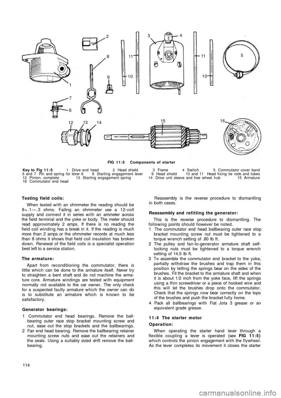
FIG 11:5 Components of starter
Key to Fig 11:5 1 Drive end head 2 Head shield 3 Frame 4 Switch 5 Commutator cover band
6 and 7 Pin and spring for lever 8 8 Starting engagement lever 9 Head shield 10 and 11 Head fixing tie rods and tubes
12 Pinion, complete 13 Starting engagement spring 14 Drive unit sleeve and free wheel hub 15 Armature
16 Commutator end head
Testing field coils:
When tested w i t h an ohmmeter the reading should be
8+.1—.3 ohms. Failing an ohmmeter use a 12-volt
supply and connect it in series w i t h an ammeter across
the field terminal and the yoke or body. The meter should
read approximately 2 amps. If there is no reading the
field coil winding has a break in it. If the reading is much
more than 2 amps or the ohmmeter records at much less
than 8 ohms it shows that field coil insulation has broken
down. Renewal of the field coils is a specialist operation
best left to a service station.
The armature:
Apart from reconditioning the commutator, there is
little which can be done to the armature itself. Never try
to straighten a bent shaft and do not machine the arma-
ture core. Armature windings are tested w i t h equipment
normally not available to the car owner. The only check
for a suspected faulty armature which the owner can do
is to substitute an armature which is known to be
satisfactory.
Generator bearings:
1 Commutator end head bearings. Remove the ball-
bearing outer race stop bracket mounting screw and
nut, ease o u t t h e stop brackets and the ballbearings.
2 Fan end head bearing. Remove the ballbearing retainer
mounting screw nuts and ease o u t t h e retainers and
the seals. Using a suitably sized drift remove the ball-
bearing.
114Reassembly is the reverse procedure to dismantling
in both cases.
Reassembly and refitting the generator:
This is the reverse procedure to dismantling. The
following points should however be noted.
1 The commutator end head ballbearing outer race stop
bracket mounting screw nut must be tightened to a
torque wrench setting of .80 Ib ft.
2 The pulley and fan-to-generator armature shaft self-
locking nuts must be tightened to a torque wrench
setting of 14.5 Ib ft.
3 To assemble the commutator end bracket to the yoke,
partially withdraw the brushes and trap them in this
position by letting the springs bear on the sides of the
brushes. Fit the bracket to the armature shaft and when
it is about 1/2 inch from the yoke face, lift the springs
using a thin screwdriver or a piece of hooked wire and
this will let the brushes drop onto the commutator.
Check that the springs now bear correctly on the tops
of the brushes and push the bracket fully home.
4 Pack all ballbearings with Fiat Jota 3 grease or an
equivalent grade grease.
11:4 The starter motor
Operation:
When operating the starter hand lever through a
flexible coupling a lever is operated (see FIG 11:5)
which controls the pinion engagement with the flywheel.
As the lever completes its movement it closes the starter
Page 108 of 128
switch contacts. The starter motor rotates driving the
engine through the pinion and ring gear. As soon as the
engine fires the starter hand lever must be released which
will open the starter switch contacts so stopping the
starter motor and the pinion will return under the action
of a spring to a neutral position.
Tests for a starter which does not operate:
Check the condition of the battery and particularly
the connections to the terminals and to earth. If the
battery is charged, switch on the lights and operate the
starter hand lever control. If the lights go dim but the
starter does not operate it shows that current is reaching
the starter motor. The probability is that the pinion of the
starter shaft is jammed in mesh due to dirty pinion splines
or a broken spring. To release the pinion engage a low
gear with the ignition switched off and rock the vehicle
backwards and forwards which should allow the pinion
to be disengaged from the flywheel ring gear. If it proves
impossible to free a jammed pinion the starter motor must
be removed for examination and repair.
If the lamps do not go dim, check the starter switch and
also check the connection between the battery and the
starter switch to ensure that they are tight and making
good electrical connection. If the starter motor still does
not work it should be removed from the power unit for
inspection.
Removing the starter:
To remove the starter motor from the power unit
proceed as follows:
1 Disconnect the positive terminal from the
battery post.
2 Release the hand lever control cable from the starter
motor engagement lever.
3 Disconnect the battery cable terminal from the starter
motor switch.
4 Remove the retaining nuts and washers holding the
starter motor to body to the transmission bellhousing
and gently ease backwards and lift away the starter
motor.
Examining the commutator and brush gear :
Refer to FIG 11:5 and remove the coverband 5. Hold
back each spring in turn and pull gently on the flexible
connection to the brush. If the brush does not move
freely remove it from its holder and polish the sides using
a fine file. Mark the brushes so that they will be replaced
in their original positions. If the brushes are so worn that
they no longer bear onto the commutator, or the brush
connector has become exposed on the running face, the
brushes must be renewed.
If the commutator is blackened it should be cleaned by
turning it against a petrol-moistened cloth. With the
brushes and commutator overhauled hold the body of the
starter motor in a vice and connect it with thick cables to a
12 volt battery. One cable should go to the starter
switch terminal and the other to the body of the starter.
The starter should run at high speed. If it does not, it
must be dismantled for further examination and testing.
F500115 Dismantling the starter:
To dismantle the starter proceed as follows:
1 Remove the coverband 5 (see FIG 11:5) and hold
back the brush springs and take out the brushes.
2 Remove the starter switch by releasing the t w o
mounting screws and lift away the switch.
3 Remove the commutator end head 16, slide off the
armature assembly from the drive unit and from the
pole shoes.
4 Release the engagement lever pin 6 and spring 7 from
the lever operating bracket on the drive end head. Lift
away the lever and withdraw the pinion assembly
complete which is shown in FIG 11:5.
Servicing the brushes
Test the brush springs with a balance, the correct
tension is 2.5 to 2.9 Ib. according to the wear of the
brushes. Fit a new spring if the tension is low.
The life of the brushes depends on the type of service
in which the vehicle is being used. In normal circum-
stances even when the starter is being used frequently,
the brushes should last more than 18,000 miles. If the
wear is found to be abnormal it will probably be found
that the commutator is either damaged or excessively
w o r n . Only Fiat replacement brushes must be used.
Testing the field coils:
Use a 12 volt bulb in one lead of a 12 volt battery.
Connect one lead to the brush connection joint to the coil
field and the other to the field coil current supply lead.
If the bulb does not light there is a break in the f i e l d coil
windings. This is not a complete test as it is still possible
for a coil to be earthed. Check this by moving the lead
from the brush connection and holding it on a clean
metal
surface on the yoke or body. If the bulb lights it shows
that the field coils are earthed.
The only sure way of curing faulty field coils is to take
the starter motor to a service station.
Examining the armature:
The armature shaft may be bent due to the starter
being operated whilst the engine is operating. Do not try
to straighten a bent shaft or machine the armature core to
obtain the correct clearance.
If the commutator is damaged or any wires or segments
have lifted from it, the assembly will have to be renewed.
Starter bearings:
Bearing bushes are of the porous bronzed type and
must not be reamed after fitting. Worn bearings should
be withdrawn by screwing a tap into them and pulling
on the tap. New bushes must be immersed in engine oil
for approximately twenty four hours before fitting. Press
them into place using a suitably sized drift which has a
spigot the length of the bearing and the diameter of the
starter shaft. When this is withdrawn after fitting, the
bore of the bush should be correct to size.
The pinion drive:
This unit is shown in FIG 11:5. The chief sources of
trouble are a dirty unit or a broken starting engagement
Page 109 of 128
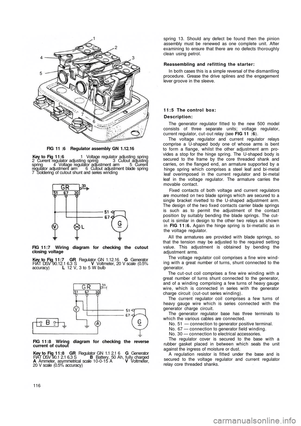
4
53 2 1
7
6
FIG 11 :6 Regulator assembly GN 1.12.16
Key to Fig 11:6 1 Voltage regulator adjusting spring
2 Current regulator adjusting spring 3 Cutout adjusting
spring 4 Voltage regulator adjustment arm 5 Current
regulator adjustment arm 6 Cutout adjustment blade spring
7 Soldering of cutout shunt and series winding
FIG 11:7 Wiring diagram for checking the cutout
closing voltage
Key to Fig 1 1 : 7 GR Regulator GN 1.12.16 G Generator
FIAT DSV 90.12.1 6.3 S V Voltmeter, 20 V scale (0.5%
accuracy) L 12 V, 3 to 5 W bulb
FIG 11:8 Wiring diagram for checking the reverse
current of cutout
Key to Fig 11:8 GR Regulator GN 1.1 2.1 6 G Generator
FIAT DSV 90.1 2.1 6.3 S B Battery, 50 Ah, fully charged
A Ammeter, asymmetrical scale 10-0-15 A V Voltmeter,
20 V scale (0.5% accuracy)
116spring 13. Should any defect be found then the pinion
assembly must be renewed as one complete unit. After
examining to ensure that there are no defects thoroughly
clean using petrol.
Reassembling and refitting the starter:
In both cases this is a simple reversal of the dismantling
procedure. Grease t h e drive splines and the engagement
lever groove in the sleeve.
11:5 The control box:
Description:
The generator regulator fitted to the new 500 model
consists of three separate
units; voltage regulator,
current regulator, cut-out relay (see FIG 11 :6).
The voltage regulator and current regulator relays
comprise a U-shaped body one of whose arms is bent
to form a flange, whilst the other adjustment arm pro-
vides a stop for the hinge spring. The U-shaped body is
secured to the frame by the core threaded shank and
carries, on the flanged end, an armature supported by a
hinge spring which comprises a steel leaf and bi-metal
leaf overimposed in the current regulator and bi-metal
leaf in the voltage regulator. The armature carries the
movable contact.
Fixed contacts of both voltage and current regulators
are mounted on t w o blade springs which are secured to a
single bracket rivetted to the U-shaped adjustment arm.
The design of the t w o fixed contacts carrier blade springs
is such as to permit the adjustment of the contact
position by suitably bending the blade springs. The cut-
out is similar in design to the other two relays as shown
in FIG 11:6. Again the hinge spring is bi-metallic as in
the voltage regulator.
All the armatures are provided w i t h blade springs, so
that the tension may be adjusted to the required setting
value. This adjustment is obtained by bending the
adjustment arms.
The voltage regulator coil comprises a fine wire wind-
ing w i t h a great number of turns, shunt connected to the
generator.
The cut-out coil comprises a fine wire winding with a
great number of turns shunt connected to the generator,
and of a winding comprising a few turns of heavy gauge
wire, which is connected in series w i t h the generator
charge circuit (cut-out series winding).
The current regulator coil comprises a few turns of
heavy gauge wire which is series connected with the
generator charge circuit.
The generator regulator base has three terminals to
which the various cables are connected.
No. 51 — connection to generator positive terminal.
No. 67 — connection to generator field winding.
No. 30 — connection to electrical accessories.
The regulator cover is secured to the base w i t h a
rubber gasket placed in between which seals the unit
against the ingress of moisture or dust.
A regulation resistor is fitted under the base and is
secured to the voltage regulator and current regulator
relay core threaded shanks.
Page 110 of 128
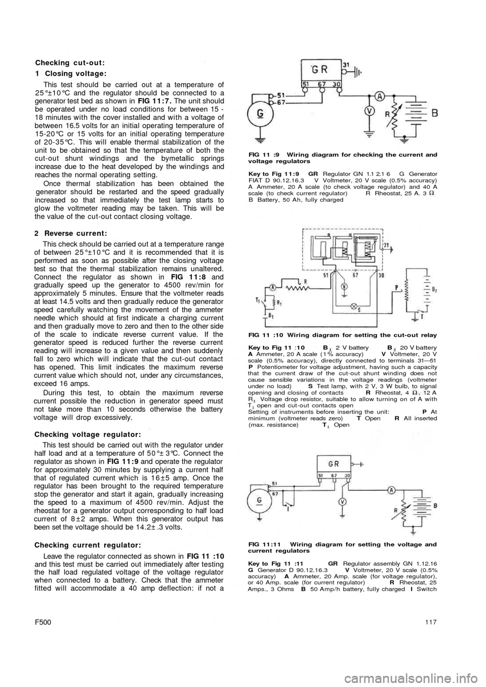
Checking cut-out:
1 Closing voltage:
This test should be carried out at a temperature of
25°±10°C and the regulator should be connected to a
generator test bed as shown in FIG 11:7. The unit should
be operated under no load conditions for between 15 -
18 minutes with the cover installed and w i t h a voltage of
between 16.5 volts for an initial operating temperature of
15-20°C or 15 volts for an initial operating temperature
of 20-35°C. This will enable thermal stabilization of the
unit to be obtained so that the temperature of both the
cut-out shunt windings and the bymetallic springs
increase due to the heat developed by the windings and
reaches the normal operating setting.
Once thermal stabilization has been obtained the
generator should be restarted and the speed gradually
increased so that immediately the test lamp starts to
glow the voltmeter reading may be taken. This will be
the value of the cut-out contact closing voltage.
2 Reverse current:
This check should be carried out at a temperature range
of between 25°±10°C and it is recommended that it is
performed as soon as possible after the closing voltage
test so that the thermal stabilization remains unaltered.
Connect the regulator as shown in FIG 11:8 and
gradually speed up the generator to 4500 rev/min for
approximately 5 minutes. Ensure that the voltmeter reads
at least 14.5 volts and then gradually reduce the generator
speed carefully watching the movement of the ammeter
needle which should at first indicate a charging current
and then gradually move to zero and then to the other side
of the scale to indicate reverse current value. If the
generator speed is reduced further the reverse current
reading will increase to a given value and then suddenly
fall to zero which will indicate that the cut-out contact
has opened. This limit indicates the maximum reverse
current value which should not, under any circumstances,
exceed 16 amps.
During this test, to obtain the maximum reverse
current possible the reduction in generator speed must
not take more than 10 seconds otherwise the battery
voltage will drop excessively.
Checking voltage regulator:
This test should be carried out w i t h the regulator under
half load and at a temperature of 50°± 3°C. Connect the
regulator as shown in FIG 11:9 and operate the regulator
for approximately 30 minutes by supplying a current half
that of regulated current which is 1 6 ±5 amp. Once the
regulator has been brought to the required temperature
stop the generator and start it again, gradually increasing
the speed to a maximum of 4500 rev/min. Adjust the
rheostat for a generator output corresponding to half load
current of 8 ± 2 amps. When this generator output has
been set the voltage should be 14.2± .3 volts.
Checking current regulator:
Leave the regulator connected as shown in
FIG 11 :10
and this test must be carried out immediately after testing
the half load regulated voltage of the voltage regulator
when connected to a battery. Check that the ammeter
fitted will accommodate a 40 amp deflection: if not a
F500117
FIG 11 :9 Wiring diagram for checking the current and
voltage regulators
Key to Fig 11:9 GR Regulator GN 1.1 2.1 6 G Generator
FIAT D 90.12.16.3 V Voltmeter, 20 V scale (0.5% accuracy)
A Ammeter, 20 A scale (to check voltage regulator) and 40 A
scale (to check current regulator)
B Battery, 50 Ah, fully chargedR Rheostat, 25 A. 3
FIG 11 :10 Wiring diagram for setting the cut-out relay
Key to Fig 11 :10 B 2 V battery B 20 V batteryA Ammeter, 20 A scale ( 1 % accuracy) V Voltmeter, 20 V
scale (0.5% accuracy), directly connected to terminals 31—51
P Potentiometer for voltage adjustment, having such a capacity
that the current draw of the cut-out shunt winding does not
cause sensible variations in the voltage readings (voltmeter
under no load) S Test lamp, with 2 V, 3 W bulb, to signal
opening and closing of contacts R Rheostat, 4 12
AR Voltage drop resistor, suitable to allow turning on of A withT open and cut-out contacts open
Setting of instruments before inserting the unit: P At
minimum (voltmeter reads zero) T Open R All inserted
(max. resistance) T Open
FIG 11:11 Wiring diagram for setting the voltage and
current regulators
Key to Fig 11 :11 GR Regulator assembly GN 1.12.16
G Generator D 90.12.16.3 V Voltmeter, 20 V scale (0.5%
accuracy) A Ammeter, 20 Amp. scale (for voltage regulator),
or 40 Amp. scale (for current regulator) R Rheostat, 25
Amps., 3 Ohms B 50 Amp/h battery, fully charged I Switch
Page 111 of 128
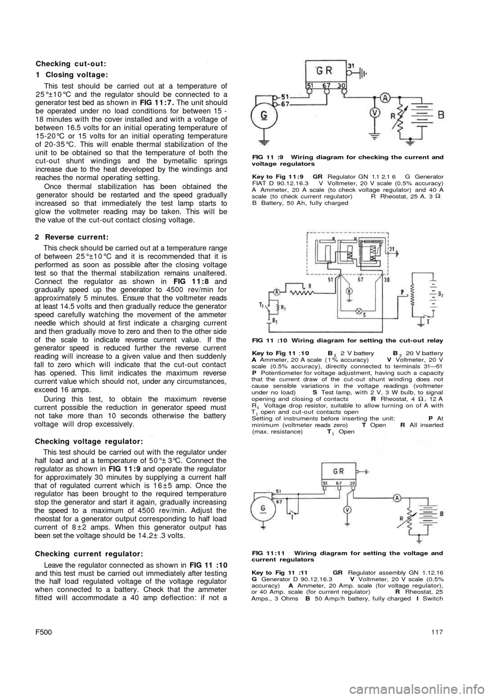
Checking cut-out:
1 Closing voltage:
This test should be carried out at a temperature of
25°±10°C and the regulator should be connected to a
generator test bed as shown in FIG 11:7. The unit should
be operated under no load conditions for between 15 -
18 minutes with the cover installed and w i t h a voltage of
between 16.5 volts for an initial operating temperature of
15-20°C or 15 volts for an initial operating temperature
of 20-35°C. This will enable thermal stabilization of the
unit to be obtained so that the temperature of both the
cut-out shunt windings and the bymetallic springs
increase due to the heat developed by the windings and
reaches the normal operating setting.
Once thermal stabilization has been obtained the
generator should be restarted and the speed gradually
increased so that immediately the test lamp starts to
glow the voltmeter reading may be taken. This will be
the value of the cut-out contact closing voltage.
2 Reverse current:
This check should be carried out at a temperature range
of between 25°±10°C and it is recommended that it is
performed as soon as possible after the closing voltage
test so that the thermal stabilization remains unaltered.
Connect the regulator as shown in FIG 11:8 and
gradually speed up the generator to 4500 rev/min for
approximately 5 minutes. Ensure that the voltmeter reads
at least 14.5 volts and then gradually reduce the generator
speed carefully watching the movement of the ammeter
needle which should at first indicate a charging current
and then gradually move to zero and then to the other side
of the scale to indicate reverse current value. If the
generator speed is reduced further the reverse current
reading will increase to a given value and then suddenly
fall to zero which will indicate that the cut-out contact
has opened. This limit indicates the maximum reverse
current value which should not, under any circumstances,
exceed 16 amps.
During this test, to obtain the maximum reverse
current possible the reduction in generator speed must
not take more than 10 seconds otherwise the battery
voltage will drop excessively.
Checking voltage regulator:
This test should be carried out w i t h the regulator under
half load and at a temperature of 50°± 3°C. Connect the
regulator as shown in FIG 11:9 and operate the regulator
for approximately 30 minutes by supplying a current half
that of regulated current which is 1 6 ±5 amp. Once the
regulator has been brought to the required temperature
stop the generator and start it again, gradually increasing
the speed to a maximum of 4500 rev/min. Adjust the
rheostat for a generator output corresponding to half load
current of 8 ± 2 amps. When this generator output has
been set the voltage should be 14.2± .3 volts.
Checking current regulator:
Leave the regulator connected as shown in
FIG 11 :10
and this test must be carried out immediately after testing
the half load regulated voltage of the voltage regulator
when connected to a battery. Check that the ammeter
fitted will accommodate a 40 amp deflection: if not a
F500117
FIG 11 :9 Wiring diagram for checking the current and
voltage regulators
Key to Fig 11:9 GR Regulator GN 1.1 2.1 6 G Generator
FIAT D 90.12.16.3 V Voltmeter, 20 V scale (0.5% accuracy)
A Ammeter, 20 A scale (to check voltage regulator) and 40 A
scale (to check current regulator)
B Battery, 50 Ah, fully chargedR Rheostat, 25 A. 3
FIG 11 :10 Wiring diagram for setting the cut-out relay
Key to Fig 11 :10 B 2 V battery B 20 V batteryA Ammeter, 20 A scale ( 1 % accuracy) V Voltmeter, 20 V
scale (0.5% accuracy), directly connected to terminals 31—51
P Potentiometer for voltage adjustment, having such a capacity
that the current draw of the cut-out shunt winding does not
cause sensible variations in the voltage readings (voltmeter
under no load) S Test lamp, with 2 V, 3 W bulb, to signal
opening and closing of contacts R Rheostat, 4 12
AR Voltage drop resistor, suitable to allow turning on of A withT open and cut-out contacts open
Setting of instruments before inserting the unit: P At
minimum (voltmeter reads zero) T Open R All inserted
(max. resistance) T Open
FIG 11:11 Wiring diagram for setting the voltage and
current regulators
Key to Fig 11 :11 GR Regulator assembly GN 1.12.16
G Generator D 90.12.16.3 V Voltmeter, 20 V scale (0.5%
accuracy) A Ammeter, 20 Amp. scale (for voltage regulator),
or 40 Amp. scale (for current regulator) R Rheostat, 25
Amps., 3 Ohms B 50 Amp/h battery, fully charged I Switch
Page 112 of 128
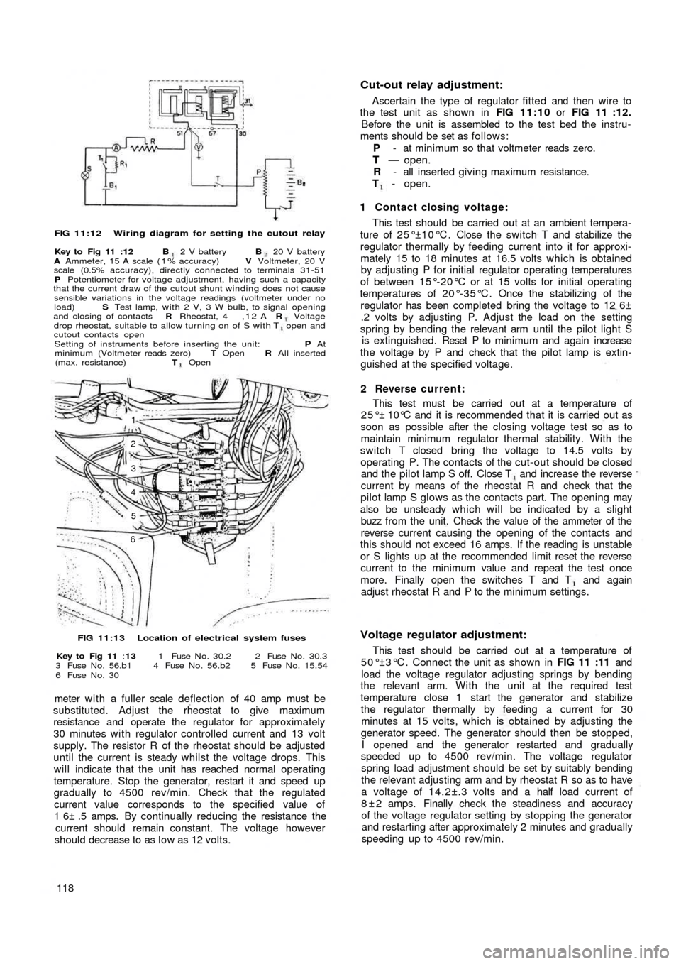
FIG 11:12 Wiring diagram for setting the cutout relay
Key to Fig 11 :12 B 2 V battery B 20 V battery
A Ammeter, 15 A scale ( 1 % accuracy) V Voltmeter, 20 V
scale (0.5% accuracy), directly connected to terminals 31-51
P Potentiometer for voltage adjustment, having such a capacity
that the current draw of the cutout shunt winding does not cause
sensible variations in the voltage readings (voltmeter under no
load) S Test lamp, with 2 V, 3 W bulb, to signal opening
and closing of contacts R Rheostat, 4 , 1 2 A R Voltagedrop rheostat, suitable to allow turning on of S with T open and
cutout contacts open
Setting of instruments before inserting the unit: P At
minimum (Voltmeter reads zero) T Open R All inserted
(max. resistance) T Open
1
2
3
4
5
6
FIG 11:13 Location of electrical system fuses
Key to Fig 11 :13 1 Fuse N o . 30.2 2 Fuse N o . 30.3
3 Fuse N o . 56.b1 4 Fuse N o . 56.b2 5 Fuse N o . 15.54
6 Fuse N o . 30
meter w i t h a fuller scale deflection of 40 amp must be
substituted. Adjust the rheostat to give maximum
resistance and operate the regulator for approximately
30 minutes with regulator controlled current and 13 volt
supply. The resistor R of the rheostat should be adjusted
until the current is steady whilst the voltage drops. This
will indicate that the unit has reached normal operating
temperature. Stop the generator, restart it and speed up
gradually to 4500 rev/min. Check that the regulated
current value corresponds to the specified value of
1 6± .5 amps. By continually reducing the resistance the
current should remain constant. The voltage however
should decrease to as l o w as 12 volts.
118
Cut-out relay adjustment:
Ascertain the type of regulator fitted and then wire to
the test unit as shown in FIG 11:10 or FIG 11 :12.
Before the unit is assembled to the test bed the instru-
ments should be set as follows:
P - at minimum so that voltmeter reads zero.
T — open.
R - all inserted giving maximum resistance.
T - open.
1 Contact closing voltage:
This test should be carried out at an ambient tempera-
ture of 25°±10°C. Close the switch T and stabilize the
regulator thermally by feeding current into it for approxi-
mately 15 to 18 minutes at 16.5 volts which is obtained
by adjusting P for initial regulator operating temperatures
of between 15°-20°C or at 15 volts for initial operating
temperatures of 20°-35°C. Once the stabilizing of the
regulator has been completed bring the voltage to 12 6±
.2 volts by adjusting P. Adjust the load on the setting
spring by bending the relevant arm until the pilot light S
is extinguished. Reset P to m inimum and again increase
the voltage by P and check that the pilot lamp is extin-
guished at the specified voltage.
2 Reverse current:
This test must be carried out at a temperature of
25°± 10°C and it is recommended that it is carried out as
soon as possible after the closing voltage test so as to
maintain minimum regulator thermal stability. With the
switch T closed bring the voltage to 14.5 volts by
operating P. The contacts of the cut-out should be closed
and the pilot lamp S off. Close T and increase the reverse
current by means of the rheostat R and check that the
pilot lamp S glows as the contacts part. The opening may
also be unsteady which will be indicated by a slight
buzz from the unit. Check the value of the ammeter of the
reverse current causing the opening of the contacts and
this should not exceed 16 amps. If the reading is unstable
or S lights up at the recommended limit reset the reverse
current to the minimum value and repeat the test once
more. Finally open the switches T and T and again
adjust rheostat R and P to the minimum settings.
Voltage regulator adjustment:
This test should be carried out at a temperature of
5 0 ° ±3 ° C . Connect the unit as shown in FIG 11 :11 and
load the voltage regulator adjusting springs by bending
the relevant arm. With the unit at the required test
temperature close 1 start the generator and stabilize
the regulator thermally by feeding a current for 30
minutes at 15 volts, which is obtained by adjusting the
generator speed. The generator should then be stopped,
I opened and the generator restarted and gradually
speeded up to 4500 rev/min. The voltage regulator
spring load adjustment should be set by suitably bending
the relevant adjusting arm and by rheostat R so as to have
a voltage of 14.2±.3 volts and a half load current of
8 ± 2 amps. Finally check the steadiness and accuracy
of the voltage regulator setting by stopping the generator
and restarting after approximately 2 minutes and gradually
speeding up to 4500 rev/min.