brake FIAT 500 2020 Owner handbook (in English)
[x] Cancel search | Manufacturer: FIAT, Model Year: 2020, Model line: 500, Model: FIAT 500 2020Pages: 228, PDF Size: 6.01 MB
Page 112 of 228
FUEL TANK CAP
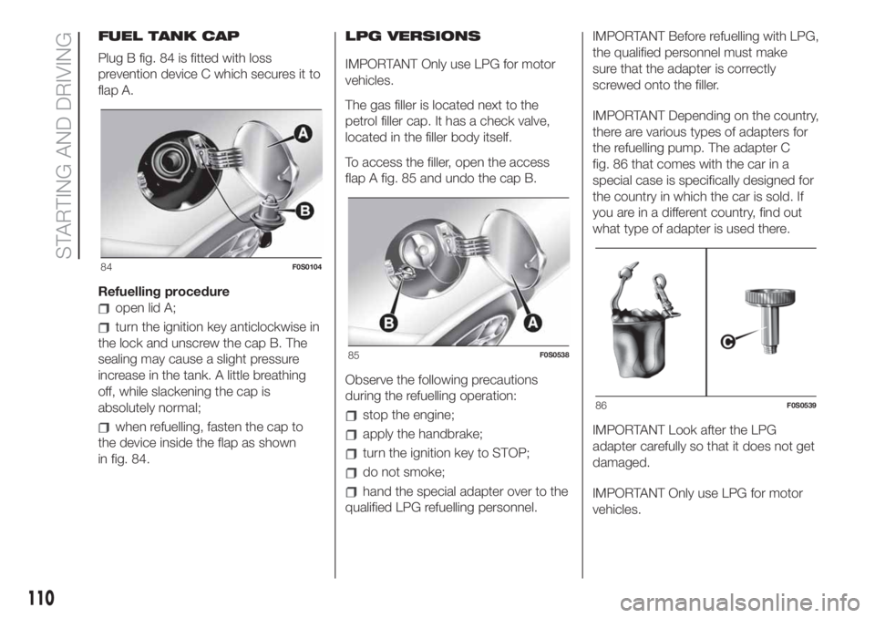
Plug B fig. 84 is fitted with loss
prevention device C which secures it to
flap A.
Refuelling procedure
open lid A;
turn the ignition key anticlockwise in
the lock and unscrew the cap B. The
sealing may cause a slight pressure
increase in the tank. A little breathing
off, while slackening the cap is
absolutely normal;
when refuelling, fasten the cap to
the device inside the flap as shown
in fig. 84.LPG VERSIONS
IMPORTANT Only use LPG for motor
vehicles.
The gas filler is located next to the
petrol filler cap. It has a check valve,
located in the filler body itself.
To access the filler, open the access
flap A fig. 85 and undo the cap B.
Observe the following precautions
during the refuelling operation:stop the engine;
apply the handbrake;
turn the ignition key to STOP;
do not smoke;
hand the special adapter over to the
qualified LPG refuelling personnel.IMPORTANT Before refuelling with LPG,
the qualified personnel must make
sure that the adapter is correctly
screwed onto the filler.
IMPORTANT Depending on the country,
there are various types of adapters for
the refuelling pump. The adapter C
fig. 86 that comes with the car in a
special case is specifically designed for
the country in which the car is sold. If
you are in a different country, find out
what type of adapter is used there.
IMPORTANT Look after the LPG
adapter carefully so that it does not get
damaged.
IMPORTANT Only use LPG for motor
vehicles.
84F0S0104
85F0S0538
86F0S0539
110
STARTING AND DRIVING
Page 114 of 228
TOWING TRAILERS
(for versions/markets, where provided)
141) 142)
IMPORTANT NOTES
For towing caravans or trailers the car
must be fitted with an approved tow
hook and an adequate electrical
system. Installation should be carried
out by specialised technicians who will
issue the required papers for travelling
on roads.
Install any specific and/or additional
door mirrors as specified by the
Highway Code.
Remember that, when towing a trailer,
steep hills are harder to climb, braking
distances increase and overtaking
takes longer depending on the overall
weight of the trailer. Engage a low gear
when driving downhill, rather than
constantly using the brake.
The weight the trailer exerts on the car
tow hook reduces the car's loading
capacity by the same amount. To make
sure that the maximum towable weight
is not exceeded (given in the vehicle
registration document) account should
be taken of the fully laden trailer,
including accessories and luggage.Respect the speed limits specific to
each country for cars towing trailers. In
any case, the top speed must not
exceed 100 km/h.
IMPORTANT The engine must be
running when using auxiliary loads other
than external lights.
IMPORTANT To install a tow hook
contact a Fiat Dealership.
WARNING
141)The ABS with which the car is
equipped will not control the braking
system of the trailer. Particular caution is
required on slippery roads.
142)Never modify the braking system of
the vehicle to control the trailer brake. The
trailer braking system must be fully
independent of the vehicle’s hydraulic
system.
112
STARTING AND DRIVING
Page 118 of 228
Light bulbs
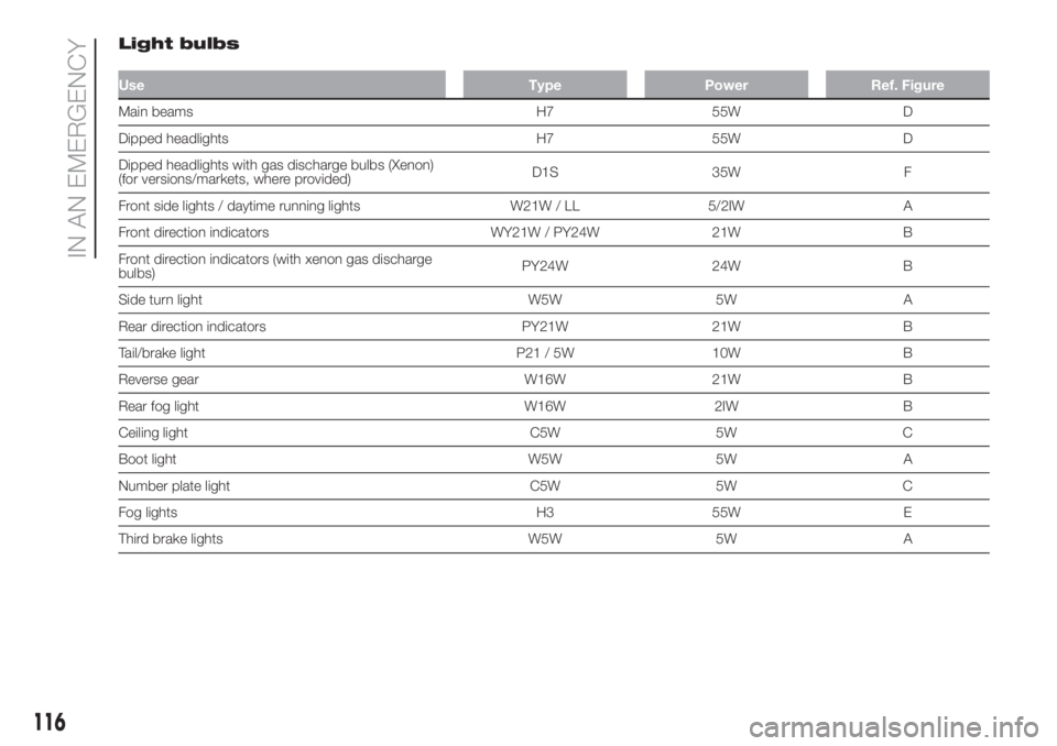
Use Type Power Ref. Figure
Main beams H7 55W D
Dipped headlights H7 55W D
Dipped headlights with gas discharge bulbs (Xenon)
(for versions/markets, where provided)D1S 35W F
Front side lights / daytime running lights W21W / LL 5/2IW A
Front direction indicators WY21W / PY24W 21W B
Front direction indicators (with xenon gas discharge
bulbs)PY24W 24W B
Side turn light W5W 5W A
Rear direction indicators PY21W 21W B
Tail/brake light P21 / 5W 10W B
Reverse gear W16W 21W B
Rear fog light W16W 2IW B
Ceiling light C5W 5W C
Boot light W5W 5W A
Number plate light C5W 5W C
Fog lights H3 55W E
Third brake lights W5W 5W A
116
IN AN EMERGENCY
Page 121 of 228
fit the new bulb, making the outline
of the metallic part coincide with the
grooves on the reflector, then reattach
the bulb holding clips;
refit the rubber cap;
close the flap C.
NOTE If the guard flap is not present,
contact a Fiat Dealership to have the
bulb replaced.
Sidelights/daytime lights
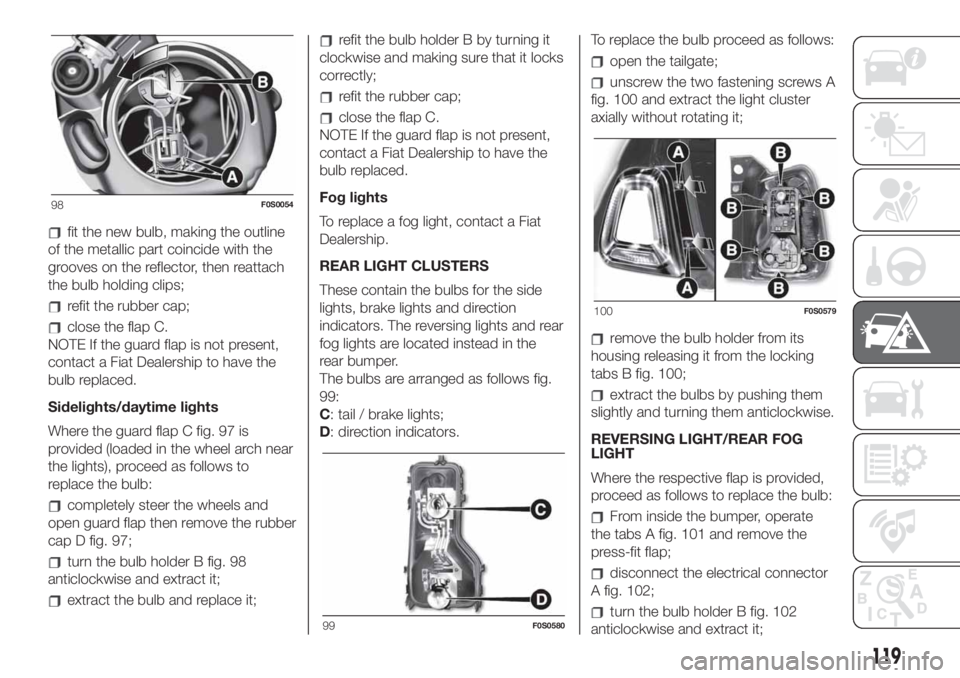
Where the guard flap C fig. 97 is
provided (loaded in the wheel arch near
the lights), proceed as follows to
replace the bulb:
completely steer the wheels and
open guard flap then remove the rubber
cap D fig. 97;
turn the bulb holder B fig. 98
anticlockwise and extract it;
extract the bulb and replace it;
refit the bulb holder B by turning it
clockwise and making sure that it locks
correctly;
refit the rubber cap;
close the flap C.
NOTE If the guard flap is not present,
contact a Fiat Dealership to have the
bulb replaced.
Fog lights
To replace a fog light, contact a Fiat
Dealership.
REAR LIGHT CLUSTERS
These contain the bulbs for the side
lights, brake lights and direction
indicators. The reversing lights and rear
fog lights are located instead in the
rear bumper.
The bulbs are arranged as follows fig.
99:
C: tail / brake lights;
D: direction indicators.To replace the bulb proceed as follows:
open the tailgate;
unscrew the two fastening screws A
fig. 100 and extract the light cluster
axially without rotating it;
remove the bulb holder from its
housing releasing it from the locking
tabs B fig. 100;
extract the bulbs by pushing them
slightly and turning them anticlockwise.
REVERSING LIGHT/REAR FOG
LIGHT
Where the respective flap is provided,
proceed as follows to replace the bulb:
From inside the bumper, operate
the tabs A fig. 101 and remove the
press-fit flap;
disconnect the electrical connector
A fig. 102;
turn the bulb holder B fig. 102
anticlockwise and extract it;
98F0S0054
99F0S0580
100F0S0579
119
Page 122 of 228
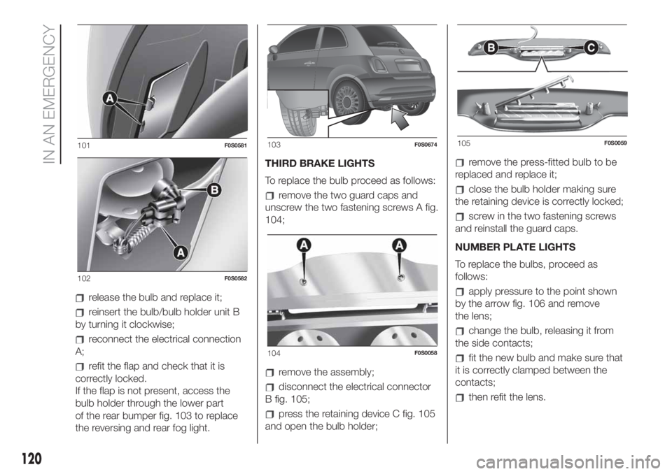
release the bulb and replace it;
reinsert the bulb/bulb holder unit B
by turning it clockwise;
reconnect the electrical connection
A;
refit the flap and check that it is
correctly locked.
If the flap is not present, access the
bulb holder through the lower part
of the rear bumper fig. 103 to replace
the reversing and rear fog light.THIRD BRAKE LIGHTS
To replace the bulb proceed as follows:
remove the two guard caps and
unscrew the two fastening screws A fig.
104;
remove the assembly;
disconnect the electrical connector
B fig. 105;
press the retaining device C fig. 105
and open the bulb holder;
remove the press-fitted bulb to be
replaced and replace it;
close the bulb holder making sure
the retaining device is correctly locked;
screw in the two fastening screws
and reinstall the guard caps.
NUMBER PLATE LIGHTS
To replace the bulbs, proceed as
follows:
apply pressure to the point shown
by the arrow fig. 106 and remove
the lens;
change the bulb, releasing it from
the side contacts;
fit the new bulb and make sure that
it is correctly clamped between the
contacts;
then refit the lens.
101F0S0581
102F0S0582
103F0S0674
104F0S0058
105F0S0059
120
IN AN EMERGENCY
Page 125 of 228
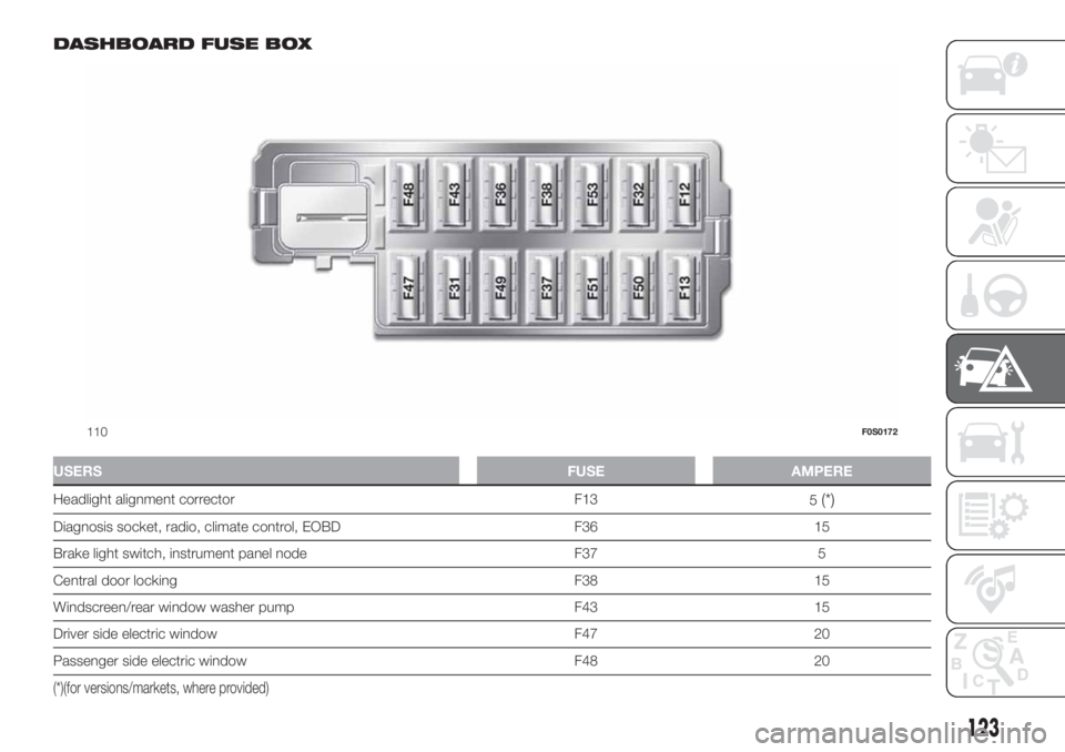
DASHBOARD FUSE BOX
USERSFUSE AMPERE
Headlight alignment corrector F13
5(*)
Diagnosis socket, radio, climate control, EOBD F36 15
Brake light switch, instrument panel node F37 5
Central door locking F38 15
Windscreen/rear window washer pump F43 15
Driver side electric window F47 20
Passenger side electric window F48 20
(*)(for versions/markets, where provided)
110F0S0172
123
Page 126 of 228
USERSFUSE AMPERE
Parking sensor, control backlighting, electric mirrors F49 5
Climate control, brake lights, clutch, electric sunroof, electric
mirrorsF51 7.5
Instrument panel node F53 5
124
IN AN EMERGENCY
Page 129 of 228
WARNING
148)If the replaced fuse blows again,
contact a Fiat Dealership.
149)Never replace a fuse with metal wires
or anything else.
150)Never replace a fuse with another with
a higher amp rating; DANGER OF FIRE.
151)If a general fuse (MEGA-FUSE,
MIDI-FUSE, MAXI-FUSE) blows contact a
Fiat Dealership.
152)Before replacing a fuse, make sure
that the ignition key has been removed and
that all the other services are switched off
and/or disengaged.
153)Contact Fiat Dealership if a safety
system (airbags, brakes), engine system
(engine, gearbox) or steering system
general protection fuse blows.
WARNING
52)If you need to wash the engine
compartment, take care not to directly hit
the engine compartment fuse box with
the water jet.
REPLACING A
WHEEL
GENERAL
INSTRUCTIONS
154) 155) 156) 157) 158) 159) 160) 161) 162)
JACK
Please note that:
the jack weight is 1.76 kg;
the jack requires no adjustment;
the jack cannot be repaired and in
the event of a fault it must be replaced
by another genuine one;
no tool other than its cranking
device may be fitted on the jack.
MAINTENANCE
prevent any dirt from depositing on
the "worm screw"
keep the "worm screw" lubricated
never modify the jack.
CONDITIONS OF
NON-USE
at temperatures lower than -40°C on
a sandy or muddy ground
on uneven ground
on steep roads
in extreme weather conditions:
thunderstorms, typhoons, hurricanes,
blizzards, storms, etc.
in direct contact with the engine or
for repairs under the car
on boats.
RAISING WITH A JACK
AND REPLACING A
WHEEL
To change a wheel, proceed as follows:
stop the car in a position that is
not dangerous for oncoming traffic
where you can change the wheel safely.
The ground must be flat and sufficiently
compact;
stop the engine, pull up the
handbrake and engage the first gear or
reverse. Wear the reflective safety
jacket (compulsory by law) before
getting out of the car;
raise the mat on the floor of the
luggage compartment;
undo the fastener B fig. 112;
take out the tool box C fig. 112 and
place it next to the wheel to be
changed;
take the space-saver wheel D fig.
112;
for vehicles with wheel cap: use the
screwdriver provided, applying leverage
to the dedicated opening on the outer
edge;
127
Page 133 of 228
159)The jack is a tool developed and
designed only for changing a wheel, if a
tyre gets punctured or damaged, on the
vehicle with which it is supplied or on other
vehicles of the same model. Any other
use, e.g. to jack up other vehicle models or
different things, is strictly prohibited. Never
use it to carry out maintenance or repairs
under the vehicle or to change summer/
winter wheels and vice versa. Never go
under the raised vehicle. If any work under
the vehicle is necessary, contact the Fiat
Service Network. Incorrect placing of
the jack can cause the vehicle to drop: use
it only in the positions indicated. Do not
use the jack for loads higher than the one
shown on its label. Never start the engine
with vehicle raised. If the vehicle is raised
more than necessary, everything can
become more unstable, with the risk of the
vehicle dropping violently. Thus, lift the
vehicle only as needed in order to access
the spare tyre.
160)Snow chains cannot be fitted to the
space-saver wheel. So, if a front (drive)
wheel is punctured and chains are needed,
a rear wheel should be fitted to the front
of the car and the space-saver wheel
should be fitted to the rear. In this way,
equipped with two normal drive wheels at
the front, they can be fitted with snow
chains, thus resolving the emergency
situation.
161)If the hub cap is not fitted correctly, it
may come off when the car is travelling.
Never tamper with the inflation valve. Never
introduce tools of any kind between rim
and tyre. Check tyre and space-saver
wheel pressures regularly, complying with
the values given in the "Technical
specifications" chapter.162)It is extremely dangerous to attempt
to change a wheel on the side of the
vehicle next to the driving lane: make sure
that the vehicle is at a sufficient distance
from the road, to avoid being run over.
163)Be very careful when removing/
refitting the hub cap due to the proximity of
the brake disc. We recommend using
heat protection gloves.
WARNING
53)When turning the jack handle make
sure that it can turn freely without scraping
your hand against the ground. The moving
components of the jack ("worm screw"
and joints) can also cause injuries: do not
touch them. If you come into contact
with lubricating grease, clean yourself
thoroughly.
54)Contact a Fiat Dealership as soon as
possible to have the correct tightening
of the wheel bolts checked.
Fix&Go kit
(where provided)
164) 165)
55)
DESCRIPTION
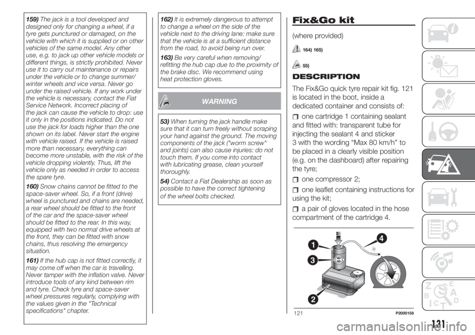
The Fix&Go quick tyre repair kit fig. 121
is located in the boot, inside a
dedicated container and consists of:
one cartridge 1 containing sealant
and fitted with: transparent tube for
injecting the sealant 4 and sticker
3 with the wording “Max 80 km/h” to
be placed in a clearly visible position
(e.g. on the dashboard) after repairing
the tyre;
one compressor 2;
one leaflet containing instructions for
using the kit;
a pair of gloves located in the hose
compartment of the cartridge 4.
121P2000158
131
Page 134 of 228
REPAIR PROCEDURE
Proceed as follows:
stop the car in a position that is not
dangerous for oncoming traffic where
you can carry out the procedure safely.
The ground must be flat and sufficiently
compact;
stop the engine, engage the hazard
warning lights and the parking brake;
wear the reflective safety jacket
before getting out of the car (anyway
comply with the laws in force in the
country you are driving in);
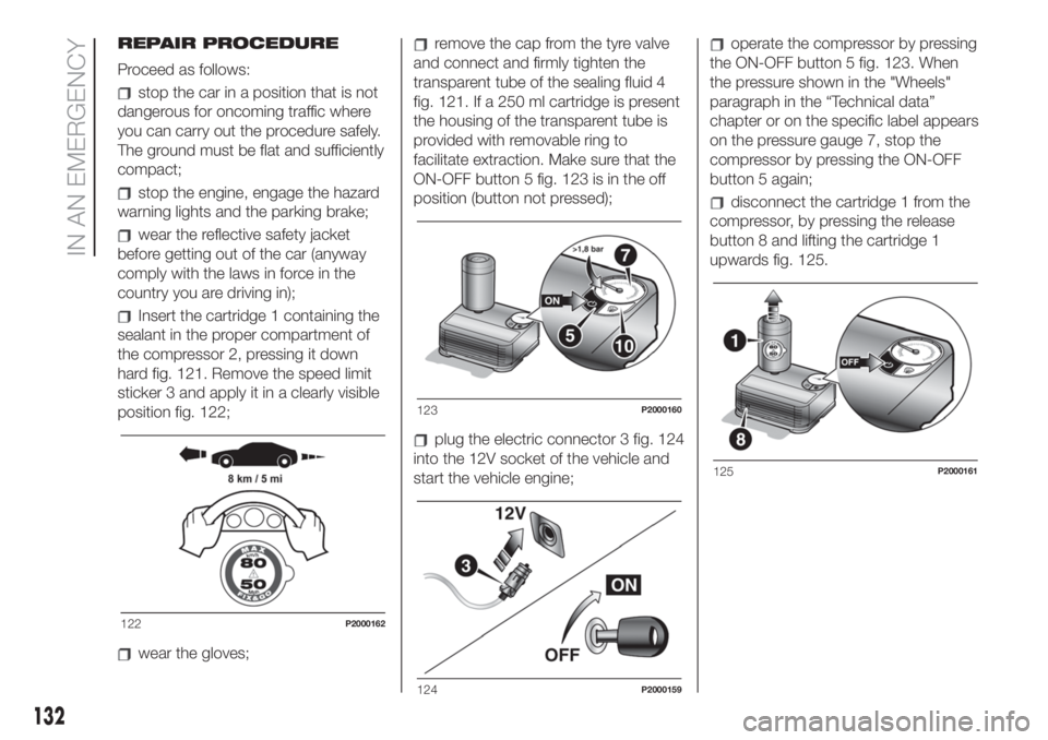
Insert the cartridge 1 containing the
sealant in the proper compartment of
the compressor 2, pressing it down
hard fig. 121. Remove the speed limit
sticker 3 and apply it in a clearly visible
position fig. 122;
wear the gloves;
remove the cap from the tyre valve
and connect and firmly tighten the
transparent tube of the sealing fluid 4
fig. 121. If a 250 ml cartridge is present
the housing of the transparent tube is
provided with removable ring to
facilitate extraction. Make sure that the
ON-OFF button 5 fig. 123 is in the off
position (button not pressed);
plug the electric connector 3 fig. 124
into the 12V socket of the vehicle and
start the vehicle engine;
operate the compressor by pressing
the ON-OFF button 5 fig. 123. When
the pressure shown in the "Wheels"
paragraph in the “Technical data”
chapter or on the specific label appears
on the pressure gauge 7, stop the
compressor by pressing the ON-OFF
button 5 again;
disconnect the cartridge 1 from the
compressor, by pressing the release
button 8 and lifting the cartridge 1
upwards fig. 125.
122P2000162
123P2000160
124P2000159
125P2000161
132
IN AN EMERGENCY