fuse box FIAT 500 2020 Owner handbook (in English)
[x] Cancel search | Manufacturer: FIAT, Model Year: 2020, Model line: 500, Model: FIAT 500 2020Pages: 228, PDF Size: 6.01 MB
Page 10 of 228
DASHBOARD
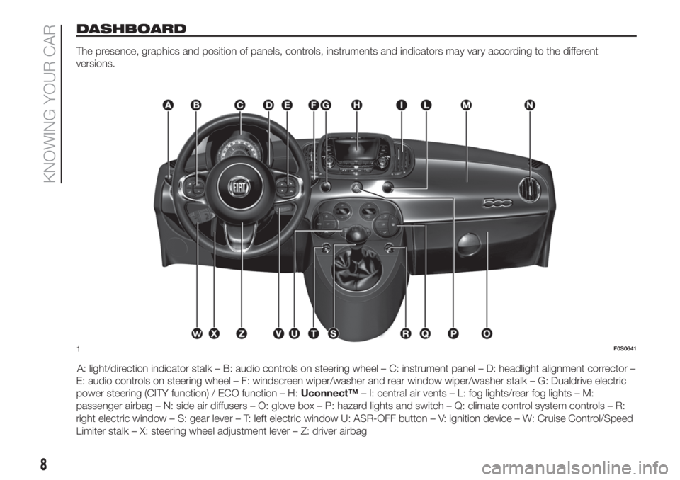
The presence, graphics and position of panels, controls, instruments and indicators may vary according to the different
versions.
A: light/direction indicator stalk – B: audio controls on steering wheel – C: instrument panel – D: headlight alignment corrector –
E: audio controls on steering wheel – F: windscreen wiper/washer and rear window wiper/washer stalk – G: Dualdrive electric
power steering (CITY function) / ECO function – H:Uconnect™– I: central air vents – L: fog lights/rear fog lights – M:
passenger airbag – N: side air diffusers – O: glove box – P: hazard lights and switch – Q: climate control system controls – R:
right electric window – S: gear lever – T: left electric window U: ASR-OFF button – V: ignition device – W: Cruise Control/Speed
Limiter stalk – X: steering wheel adjustment lever – Z: driver airbag
1F0S0641
8
KNOWING YOUR CAR
Page 11 of 228
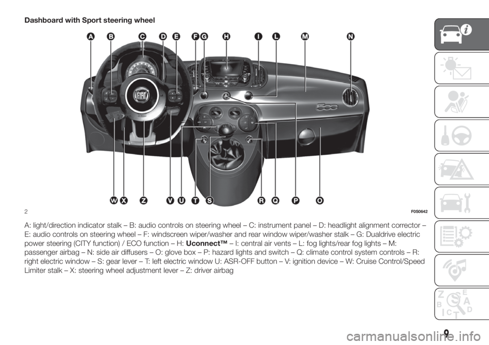
Dashboard with Sport steering wheel
A: light/direction indicator stalk – B: audio controls on steering wheel – C: instrument panel – D: headlight alignment corrector –
E: audio controls on steering wheel – F: windscreen wiper/washer and rear window wiper/washer stalk – G: Dualdrive electric
power steering (CITY function) / ECO function – H:Uconnect™– I: central air vents – L: fog lights/rear fog lights – M:
passenger airbag – N: side air diffusers – O: glove box – P: hazard lights and switch – Q: climate control system controls – R:
right electric window – S: gear lever – T: left electric window U: ASR-OFF button – V: ignition device – W: Cruise Control/Speed
Limiter stalk – X: steering wheel adjustment lever – Z: driver airbag
2F0S0642
9
Page 30 of 228
ROOF
FIXED GLASS SUNROOF
(for versions/markets, where provided)
The roof comprises a wide fixed glass
panel and a manually-operated sun
blind. The blind can be used in the "all
closed" or "all open" positions.
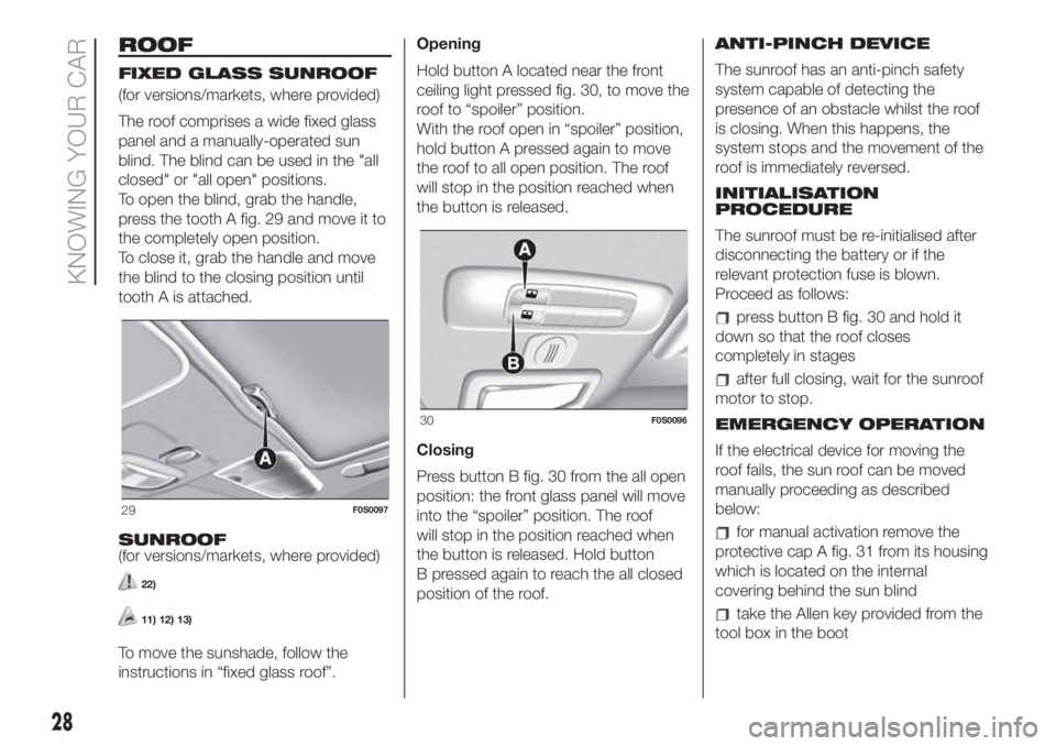
To open the blind, grab the handle,
press the tooth A fig. 29 and move it to
the completely open position.
To close it, grab the handle and move
the blind to the closing position until
tooth A is attached.
SUNROOF
(for versions/markets, where provided)
22)
11) 12) 13)
To move the sunshade, follow the
instructions in “fixed glass roof”.Opening
Hold button A located near the front
ceiling light pressed fig. 30, to move the
roof to “spoiler” position.
With the roof open in “spoiler” position,
hold button A pressed again to move
the roof to all open position. The roof
will stop in the position reached when
the button is released.
Closing
Press button B fig. 30 from the all open
position: the front glass panel will move
into the “spoiler” position. The roof
will stop in the position reached when
the button is released. Hold button
B pressed again to reach the all closed
position of the roof.ANTI-PINCH DEVICE
The sunroof has an anti-pinch safety
system capable of detecting the
presence of an obstacle whilst the roof
is closing. When this happens, the
system stops and the movement of the
roof is immediately reversed.
INITIALISATION
PROCEDURE
The sunroof must be re-initialised after
disconnecting the battery or if the
relevant protection fuse is blown.
Proceed as follows:
press button B fig. 30 and hold it
down so that the roof closes
completely in stages
after full closing, wait for the sunroof
motor to stop.
EMERGENCY OPERATION
If the electrical device for moving the
roof fails, the sun roof can be moved
manually proceeding as described
below:
for manual activation remove the
protective cap A fig. 31 from its housing
which is located on the internal
covering behind the sun blind
take the Allen key provided from the
tool box in the boot
29F0S0097
30F0S0096
28
KNOWING YOUR CAR
Page 104 of 228
129)Before starting any servicing
operation, stop the engine and remove the
key from the ignition switch to operate
the steering lock, particularly when the
wheels do not touch the ground. If this is
not possible (for example if the key needs
to be turned to MAR or the engine must be
running), remove the main fuse that
protects the electric power steering.START&STOP
SYSTEM
130) 131) 132) 133)
46)
(for versions/markets, where provided)
The Start&Stop system automatically
stops the engine each time the car
is stationary and starts it again when
the driver wants to move off.
In this way, the vehicle efficiency is
increased, by reducing consumption,
dangerous gas emissions and sound
pollution.
OPERATING MODE
Stopping the engine
With manual transmission: with the car
stationary, the engine stops with the
transmission in neutral and the clutch
pedal released.
With Dualogic gearbox: the engine
stops if the car is at a standstill and the
brake pedal is pressed. This condition
can be maintained even if the brake
pedal is not depressed, if the gear lever
is in position N (Neutral).NOTE The engine can only be stopped
automatically over about 10 km/h, to
prevent the engine from being
repeatedly stopped when driving at
walking pace.
Stopping of the engine is indicated by
the warning light or the symbol
on
the instrument panel switching on
(on some versions, together with a
message on the display).
Restarting the engine
With manual transmission: press the
clutch pedal.
With Dualogic gearbox: if the gear lever
is in position N (Neutral), place it in
any other gear, otherwise release the
brake pedal or move the gear lever
to+,–or R (Reverse).
MANUAL SYSTEM
ACTIVATION/
DEACTIVATION
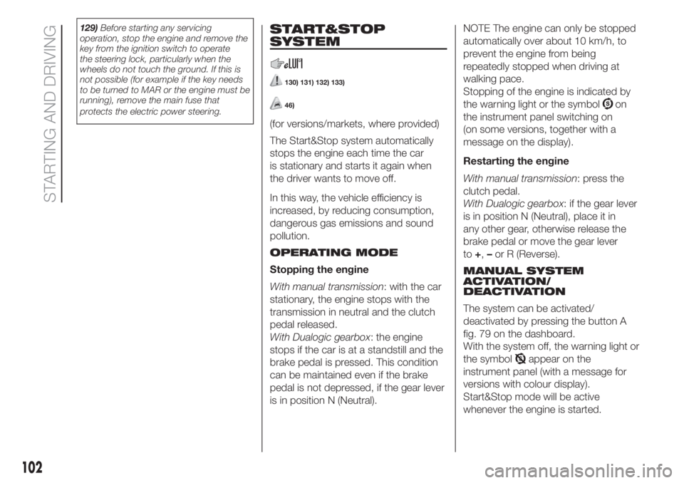
The system can be activated/
deactivated by pressing the button A
fig. 79 on the dashboard.
With the system off, the warning light or
the symbol
appear on the
instrument panel (with a message for
versions with colour display).
Start&Stop mode will be active
whenever the engine is started.
102
STARTING AND DRIVING
Page 123 of 228
WARNING
143)Modifications or repairs to the electric
system that are not carried out properly
or do not take the system technical
specifications into account can cause
malfunctions leading to the risk of fire.
144)Halogen bulbs contain pressurised
gas, in the case of breakage they may
burst causing glass fragments to be
projected outwards.
145)Only replace the light bulbs when the
engine is off and in a position that does
not interfere with traffic and lets you safely
replace them (see the description in the
“Replacement” paragraph). Also ensure
that the engine is cold, to prevent the risk
of burns.
146)Before replacing the bulb, wait for the
exhaust ducts to cool down: DANGER
OF SCALDING!147)Due to the high power supply voltage,
gas discharge bulbs (Xenon) should only
be replaced by specialised personnel:
danger of death! Contact a Fiat Dealership.
WARNING
49)Halogen bulbs must be handled
holding the metallic part only. Touching the
transparent part of the bulb with your
fingers may reduce the intensity of the
emitted light and even reduce the lifespan
of the bulb. In the event of accidental
contact, wipe the bulb with a cloth
moistened with alcohol and let the bulb
dry.
50)Where possible, it is advisable to have
bulbs changed at a Fiat Dealership. The
correct operation and direction of the
external lights are absolutely essential for
the safety of the car and of compliance
with the law.
51)The intervention must be carried out
taking all precautions necessary to avoid
damaging the bodywork (please use a
sufficiently rigid and appropriately thick
plastic card).
REPLACING FUSES
148) 149) 150) 151) 152) 153)
DASHBOARD FUSE BOX
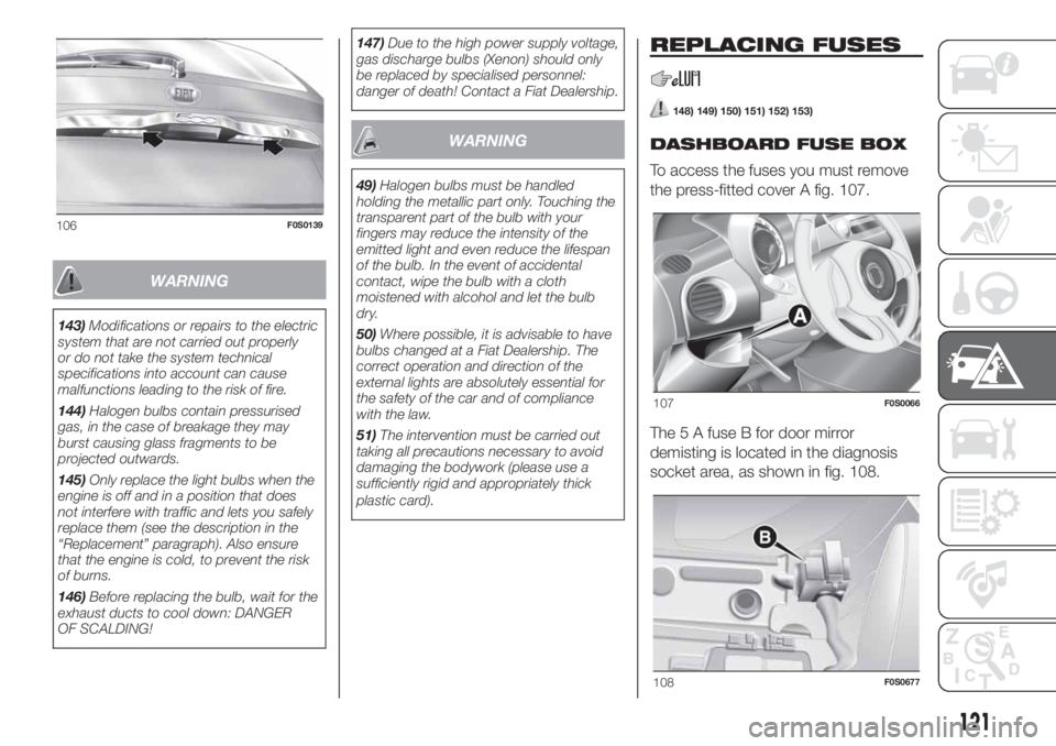
To access the fuses you must remove
the press-fitted cover A fig. 107.
The 5 A fuse B for door mirror
demisting is located in the diagnosis
socket area, as shown in fig. 108.
106F0S0139
107F0S0066
108F0S0677
121
Page 124 of 228

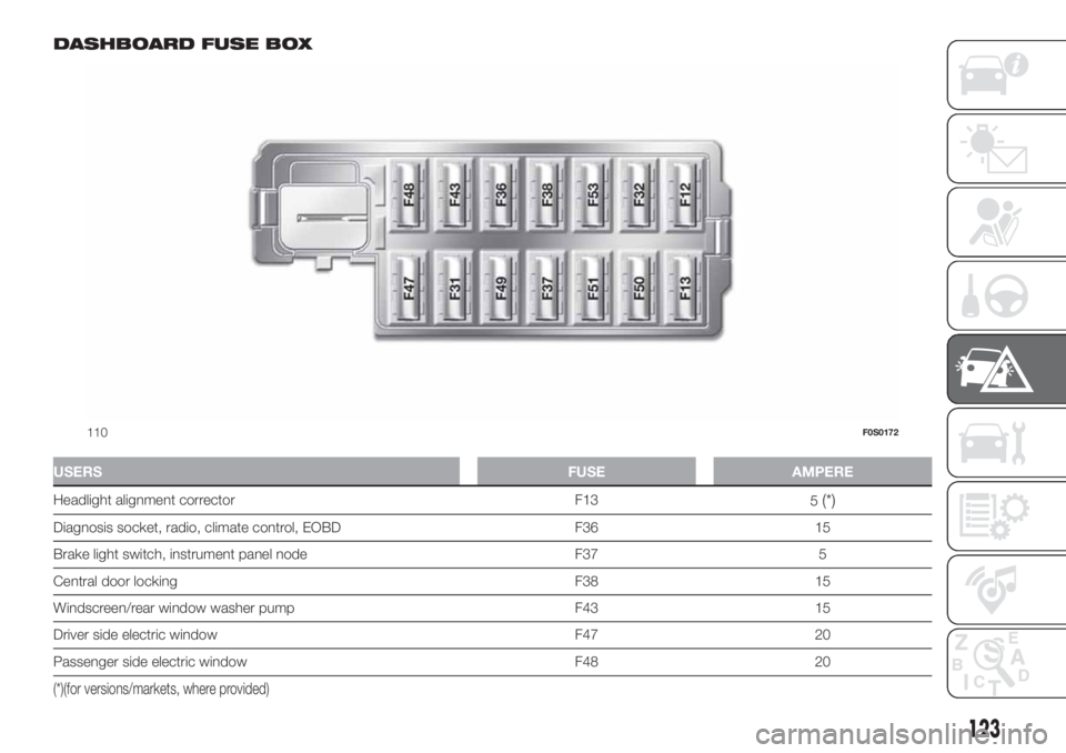
The dashboard fuse box shown is
located in the lower area next to the
pedal board.
ENGINE COMPARTMENT
JUNCTION BOX
52)
The fusebox is located on the right side
of the engine compartment. To access
the fuses, proceed as follows:
Fully press screw A fig. 109;
at the same time slowly rotate the
screw anticlockwise, until resistance is
encountered (do not overtighten);
slowly release the screw;
opening is indicated by the entire
screw head coming out of its seat;
remove cover B, sliding it upwards
on the side guides, as indicated in
the figure.Once the fuse has been replaced,
proceed as follows:
correctly refit the cover B in the side
guides of the casing;
slide it down completely from the
top;
fully tighten screw A using the
screwdriver provided;
at the same time slowly rotate the
screw clockwise, until resistance is
encountered (do not overtighten);
slowly release the screw;
closure is indicated by the securing
of the entire screw head in its housing.
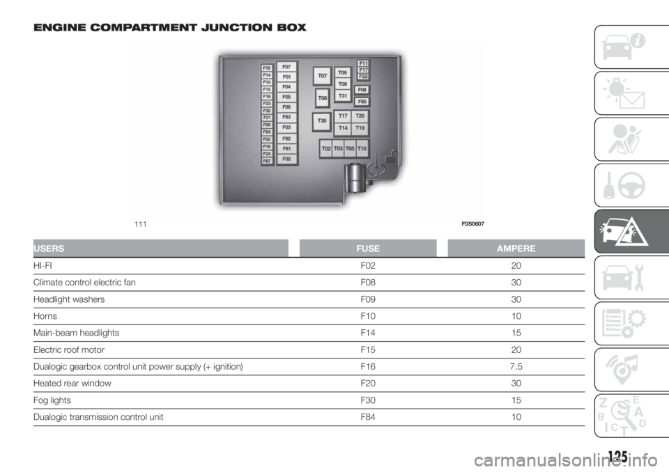
The number identifying the electrical
component corresponding to each fuse
is shown on the control unit cover.
LPG versions
The LPG system components are
protected by specific fuses. Contact a
Fiat Dealership for replacement.
109F0S0606
122
IN AN EMERGENCY
Page 125 of 228
DASHBOARD FUSE BOX
USERSFUSE AMPERE
Headlight alignment corrector F13
5(*)
Diagnosis socket, radio, climate control, EOBD F36 15
Brake light switch, instrument panel node F37 5
Central door locking F38 15
Windscreen/rear window washer pump F43 15
Driver side electric window F47 20
Passenger side electric window F48 20
(*)(for versions/markets, where provided)
110F0S0172
123
Page 127 of 228
ENGINE COMPARTMENT JUNCTION BOX
USERSFUSE AMPERE
HI-FIF02 20
Climate control electric fan F08 30
Headlight washers F09 30
HornsF10 10
Main-beam headlights F14 15
Electric roof motor F15 20
Dualogic gearbox control unit power supply (+ ignition) F16 7.5
Heated rear window F20 30
Fog lightsF30 15
Dualogic transmission control unit F84 10
111F0S0607
125
Page 129 of 228
WARNING
148)If the replaced fuse blows again,
contact a Fiat Dealership.
149)Never replace a fuse with metal wires
or anything else.
150)Never replace a fuse with another with
a higher amp rating; DANGER OF FIRE.
151)If a general fuse (MEGA-FUSE,
MIDI-FUSE, MAXI-FUSE) blows contact a
Fiat Dealership.
152)Before replacing a fuse, make sure
that the ignition key has been removed and
that all the other services are switched off
and/or disengaged.
153)Contact Fiat Dealership if a safety
system (airbags, brakes), engine system
(engine, gearbox) or steering system
general protection fuse blows.
WARNING
52)If you need to wash the engine
compartment, take care not to directly hit
the engine compartment fuse box with
the water jet.
REPLACING A
WHEEL
GENERAL
INSTRUCTIONS
154) 155) 156) 157) 158) 159) 160) 161) 162)
JACK
Please note that:
the jack weight is 1.76 kg;
the jack requires no adjustment;
the jack cannot be repaired and in
the event of a fault it must be replaced
by another genuine one;
no tool other than its cranking
device may be fitted on the jack.
MAINTENANCE
prevent any dirt from depositing on
the "worm screw"
keep the "worm screw" lubricated
never modify the jack.
CONDITIONS OF
NON-USE
at temperatures lower than -40°C on
a sandy or muddy ground
on uneven ground
on steep roads
in extreme weather conditions:
thunderstorms, typhoons, hurricanes,
blizzards, storms, etc.
in direct contact with the engine or
for repairs under the car
on boats.
RAISING WITH A JACK
AND REPLACING A
WHEEL
To change a wheel, proceed as follows:
stop the car in a position that is
not dangerous for oncoming traffic
where you can change the wheel safely.
The ground must be flat and sufficiently
compact;
stop the engine, pull up the
handbrake and engage the first gear or
reverse. Wear the reflective safety
jacket (compulsory by law) before
getting out of the car;
raise the mat on the floor of the
luggage compartment;
undo the fastener B fig. 112;
take out the tool box C fig. 112 and
place it next to the wheel to be
changed;
take the space-saver wheel D fig.
112;
for vehicles with wheel cap: use the
screwdriver provided, applying leverage
to the dedicated opening on the outer
edge;
127