ECO mode FIAT 500 ABARTH 2014 2.G User Guide
[x] Cancel search | Manufacturer: FIAT, Model Year: 2014, Model line: 500 ABARTH, Model: FIAT 500 ABARTH 2014 2.GPages: 88, PDF Size: 5.56 MB
Page 3 of 88
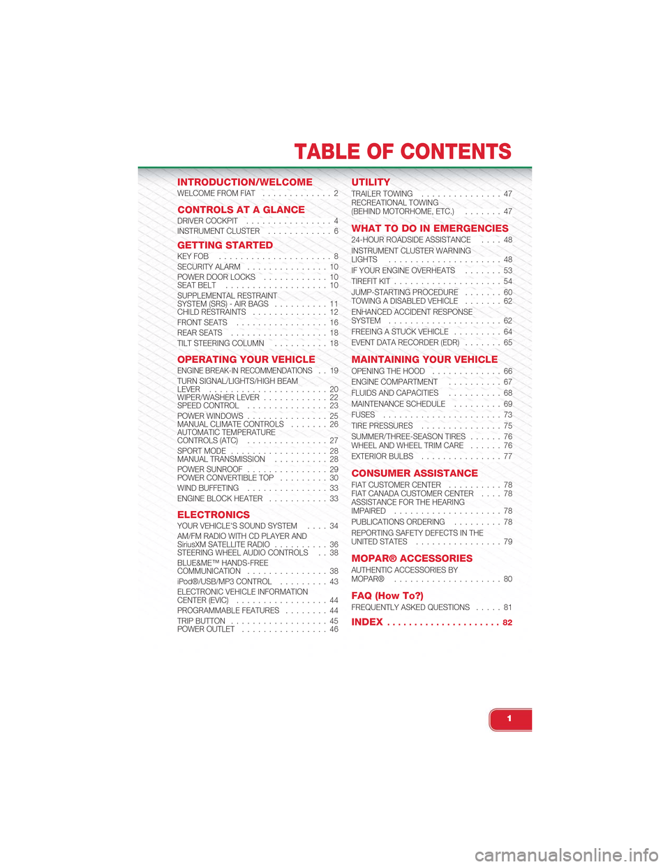
INTRODUCTION/WELCOMEWELCOME FROM FIAT............. 2
CONTROLS AT A GLANCEDRIVER COCKPIT................ 4INSTRUMENT CLUSTER............ 6
GETTING STARTEDKEY FOB . . . . . . . . . . . . . . . . . . . . . 8SECURITY ALARM. . . . . . . . . . . . . . . 10POWER DOOR LOCKS. . . . . . . . . . . . 10SEAT BELT. . . . . . . . . . . . . . . . . . . 10SUPPLEMENTAL RESTRAINTSYSTEM (SRS) - AIR BAGS. . . . . . . . . . 11CHILD RESTRAINTS. . . . . . . . . . . . . . 12FRONT SEATS. . . . . . . . . . . . . . . . . 16REAR SEATS. . . . . . . . . . . . . . . . . . 18TILT STEERING COLUMN. . . . . . . . . . 18
OPERATING YOUR VEHICLEENGINE BREAK-IN RECOMMENDATIONS. . 19TURN SIGNAL/LIGHTS/HIGH BEAMLEVER. . . . . . . . . . . . . . . . . . . . . . 20WIPER/WASHER LEVER. . . . . . . . . . . . 22SPEED CONTROL. . . . . . . . . . . . . . . 23POWER WINDOWS. . . . . . . . . . . . . . . 25MANUAL CLIMATE CONTROLS. . . . . . . 26AUTOMATIC TEMPERATURECONTROLS (ATC). . . . . . . . . . . . . . . 27SPORT MODE. . . . . . . . . . . . . . . . . . 28MANUAL TRANSMISSION. . . . . . . . . . 28POWER SUNROOF. . . . . . . . . . . . . . . 29POWER CONVERTIBLE TOP. . . . . . . . . 30WIND BUFFETING. . . . . . . . . . . . . . . 33ENGINE BLOCK HEATER. . . . . . . . . . . 33
ELECTRONICSYOUR VEHICLE'S SOUND SYSTEM. . . . 34AM/FM RADIO WITH CD PLAYER ANDSiriusXM SATELLITE RADIO. . . . . . . . . . 36STEERING WHEEL AUDIO CONTROLS . . 38BLUE&ME™ HANDS-FREECOMMUNICATION. . . . . . . . . . . . . . . 38iPod®/USB/MP3 CONTROL. . . . . . . . . 43ELECTRONIC VEHICLE INFORMATIONCENTER (EVIC). . . . . . . . . . . . . . . . . 44PROGRAMMABLE FEATURES. . . . . . . . 44TRIP BUTTON. . . . . . . . . . . . . . . . . . 45POWER OUTLET. . . . . . . . . . . . . . . . 46
UTILITY
TRAILER TOWING. . . . . . . . . . . . . . . 47RECREATIONAL TOWING(BEHIND MOTORHOME, ETC.). . . . . . . 47
WHAT TO DO IN EMERGENCIES
24-HOUR ROADSIDE ASSISTANCE. . . . 48INSTRUMENT CLUSTER WARNINGLIGHTS. . . . . . . . . . . . . . . . . . . . . 48IF YOUR ENGINE OVERHEATS. . . . . . . 53TIREFIT KIT. . . . . . . . . . . . . . . . . . . . 54JUMP-STARTING PROCEDURE. . . . . . . 60TOWING A DISABLED VEHICLE. . . . . . . 62ENHANCED ACCIDENT RESPONSESYSTEM. . . . . . . . . . . . . . . . . . . . . 62FREEING A STUCK VEHICLE. . . . . . . . . 64EVENT DATA RECORDER (EDR). . . . . . . 65
MAINTAINING YOUR VEHICLE
OPENING THE HOOD. . . . . . . . . . . . . 66ENGINE COMPARTMENT. . . . . . . . . . 67FLUIDS AND CAPACITIES. . . . . . . . . . 68MAINTENANCE SCHEDULE. . . . . . . . . 69FUSES. . . . . . . . . . . . . . . . . . . . . . 73TIRE PRESSURES. . . . . . . . . . . . . . . 75SUMMER/THREE-SEASON TIRES. . . . . . 76WHEEL AND WHEEL TRIM CARE. . . . . . 76EXTERIOR BULBS. . . . . . . . . . . . . . . 77
CONSUMER ASSISTANCE
FIAT CUSTOMER CENTER. . . . . . . . . . 78FIAT CANADA CUSTOMER CENTER. . . . 78ASSISTANCE FOR THE HEARINGIMPAIRED. . . . . . . . . . . . . . . . . . . . 78PUBLICATIONS ORDERING. . . . . . . . . 78REPORTING SAFETY DEFECTS IN THEUNITED STATES. . . . . . . . . . . . . . . . 79
MOPAR® ACCESSORIES
AUTHENTIC ACCESSORIES BYMOPAR®. . . . . . . . . . . . . . . . . . . . 80
FAQ (How To?)
FREQUENTLY ASKED QUESTIONS. . . . . 81
INDEX. . . . . . . . . . . . . . . . . . . . . 82
TABLE OF CONTENTS
1
Page 16 of 88
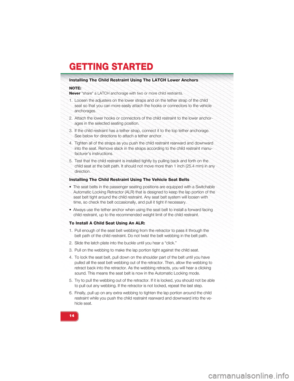
Installing The Child Restraint Using The LATCH Lower Anchors
NOTE:
Never“share” a LATCH anchorage with two or more child restraints.
1. Loosen the adjusters on the lower straps and on the tether strap of the child
seat so that you can more easily attach the hooks or connectors to the vehicle
anchorages.
2. Attach the lower hooks or connectors of the child restraint to the lower anchor-
ages in the selected seating position.
3. If the child restraint has a tether strap, connect it to the top tether anchorage.
See below for directions to attach a tether anchor.
4. Tighten all of the straps as you push the child restraint rearward and downward
into the seat. Remove slack in the straps according to the child restraint manu-
facturer’s instructions.
5. Test that the child restraint is installed tightly by pulling back and forth on the
child seat at the belt path. It should not move more than 1 inch (25.4 mm) in any
direction.
Installing The Child Restraint Using The Vehicle Seat Belts
• The seat belts in the passenger seating positions are equipped with a Switchable
Automatic Locking Retractor (ALR) that is designed to keep the lap portion of the
seat belt tight around the child restraint. Any seat belt system will loosen with
time, so check the belt occasionally, and pull it tight if necessary.
• Always use the tether anchor when using the seat belt to install a forward facing
child restraint, up to the recommended weight limit of the child restraint.
To Install A Child Seat Using An ALR:
1. Pull enough of the seat belt webbing from the retractor to pass it through the
belt path of the child restraint. Do not twist the belt webbing in the belt path.
2. Slide the latch plate into the buckle until you hear a “click.”
3. Pull on the webbing to make the lap portion tight against the child seat.
4. To lock the seat belt, pull down on the shoulder part of the belt until you have
pulled all the seat belt webbing out of the retractor. Then, allow the webbing to
retract back into the retractor. As the webbing retracts, you will hear a clicking
sound. This means the seat belt is now in the Automatic Locking mode.
5. Try to pull the webbing out of the retractor. If it is locked, you should not be able
to pull out any webbing. If the retractor is not locked, repeat the last step.
6. Finally, pull up on any extra webbing to tighten the lap portion around the child
restraint while you push the child restraint rearward and downward into the ve-
hicle seat.
GETTING STARTED
14
Page 21 of 88
ENGINE BREAK-IN RECOMMENDATIONS
• A long break-in period is not required for the engine and drivetrain (transmission
and axle) in your vehicle.
• Drive moderately during the first 300 miles (500 km). After the initial 60 miles
(100 km), speeds up to 50 or 55 mph (80 or 90 km/h) are desirable.
• While cruising, brief full-throttle acceleration within the limits of local traffic laws
contributes to a good break-in. Wide-open throttle acceleration in low gear can
be detrimental and should be avoided.
• The engine oil installed in the engine at the factory is a high-quality energy con-
serving type lubricant. Oil changes should be consistent with anticipated climate
conditions under which vehicle operations will occur. For the recommended vis-
cosity and quality grades, refer to “Maintaining Your Vehicle.”
NOTE:
A new engine may consume some oil during its first few thousand miles (kilometers)
of operation. This should be considered a normal part of the break-in and not inter-
preted as an indication of an engine problem or malfunction.
CAUTION!
Never use Non-Detergent Oil or Straight Mineral Oil in the engine or damage may
result.
OPERATING YOUR VEHICLE
19
Page 32 of 88
WARNING!
• Do not let children play with the sunroof, or leave children unattended in the
vehicle, and do not leave the key in or near the vehicle (or in a location ac-
cessible to children). Occupants, particularly unattended children, can be-
come entrapped by the power sunroof while operating the power sunroof
switch. Such entrapment may result in serious injury or death.
• In a collision, there is a greater risk of being thrown from a vehicle with an
open sunroof. You could also be seriously injured or killed. Always fasten
your seat belt properly and make sure all passengers are properly secured.
• Do not allow small children to operate the sunroof. Never allow your fingers,
other body parts, or any object to project through the sunroof opening. Injury
may result.
POWER CONVERTIBLE TOP
On vehicles equipped with a power convertible top, the power convertible top
switch is located on the overhead console. The switch contains two buttons.
The passenger side button, is used to open the power top, and the driver side but-
ton, is used to close the power top.
NOTE:
• The power top buttons will operate when the ignition switch is turned to the
ACC/ON/RUN position.
• The power top can be remotely operated with the key fob. Refer to “Opening
Power Top Remote Function” in “Things To Know Before Starting” in the Owner’s
Manual on the DVD for more information.
Lowering The Power Top
Auto Open
Push the top open button approximately one second for the three-quarter open/
spoiler position. Push the top open button for approximately one second a second
time to fully open the convertible top.
Manual Open
For manual open, push and hold the open button until desired roof position or until
spoiler position.
NOTE:
Vertical movement only operates in auto open/close mode.
OPERATING YOUR VEHICLE
30
Page 34 of 88
Power Convertible Top Relearn Procedure
If your power convertible top does not operate in the Auto Opening/Closing mode
(automatically opening/closing to the one-quarter open and three-quarter open
comfort stops), or if the remote keyless power top function is inoperable, or if the
trunk lid does not open - the following relearn procedure may be necessary.
1. Confirm that the door/trunk lid are closed.
2. Begin with the top in the fully closed position (using manual mode).
3. Hold the OPEN button to move the top to the fully open position.
4. CONTINUE to hold the OPEN button for an additional three seconds.
5. Release the OPEN button.
6. Hold the CLOSED button to move the top to the fully closed position.
7. CONTINUE to hold the CLOSED button until the top begins to cycle fully open,
then release the CLOSED button.
At the end of step 7 the top will automatically cycle to the fully open position, and
then close to the 1/4 open position.
This will confirm that the relearn procedure was successful.
Auto Open/Close will now be functional. Trunk lid operation will be functional. Re-
mote Keyless Power Top Function will be functional.
NOTE:
DO NOT interrupt this activity.
If the power convertible top does not relearn repeat the procedure a second time.
Wind Stop
The Wind Stop installs in the backseat area of the vehicle. The Wind Stop will not inter-
fere with power top operation. Therefore, it can remain installed when the top is up.
OPERATING YOUR VEHICLE
32
Page 40 of 88
STEERING WHEEL AUDIO CONTROLS
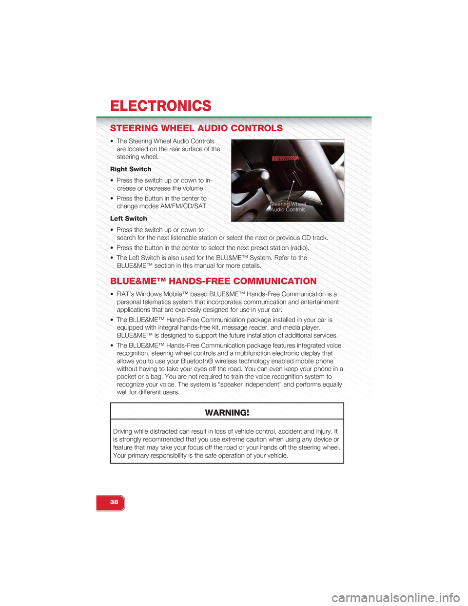
• The Steering Wheel Audio Controls
are located on the rear surface of the
steering wheel.
Right Switch
• Press the switch up or down to in-
crease or decrease the volume.
• Press the button in the center to
change modes AM/FM/CD/SAT.
Left Switch
• Press the switch up or down to
search for the next listenable station or select the next or previous CD track.
• Press the button in the center to select the next preset station (radio).
• The Left Switch is also used for the BLU&ME™ System. Refer to the
BLUE&ME™ section in this manual for more details.
BLUE&ME™ HANDS-FREE COMMUNICATION
• FIAT’s Windows Mobile™ based BLUE&ME™ Hands-Free Communication is a
personal telematics system that incorporates communication and entertainment
applications that are expressly designed for use in your car.
• The BLUE&ME™ Hands-Free Communication package installed in your car is
equipped with integral hands-free kit, message reader, and media player.
BLUE&ME™ is designed to support the future installation of additional services.
• The BLUE&ME™ Hands-Free Communication package features integrated voice
recognition, steering wheel controls and a multifunction electronic display that
allows you to use your Bluetooth® wireless technology enabled mobile phone
without having to take your eyes off the road. You can even keep your phone in a
pocket or a bag. You are not required to train the voice recognition system to
recognize your voice. The system is “speaker independent” and performs equally
well for different users.
WARNING!
Driving while distracted can result in loss of vehicle control, accident and injury. It
is strongly recommended that you use extreme caution when using any device or
feature that may take your focus off the road or your hands off the steering wheel.
Your primary responsibility is the safe operation of your vehicle.
ELECTRONICS
38
Page 46 of 88
ELECTRONIC VEHICLE INFORMATION
CENTER (EVIC)
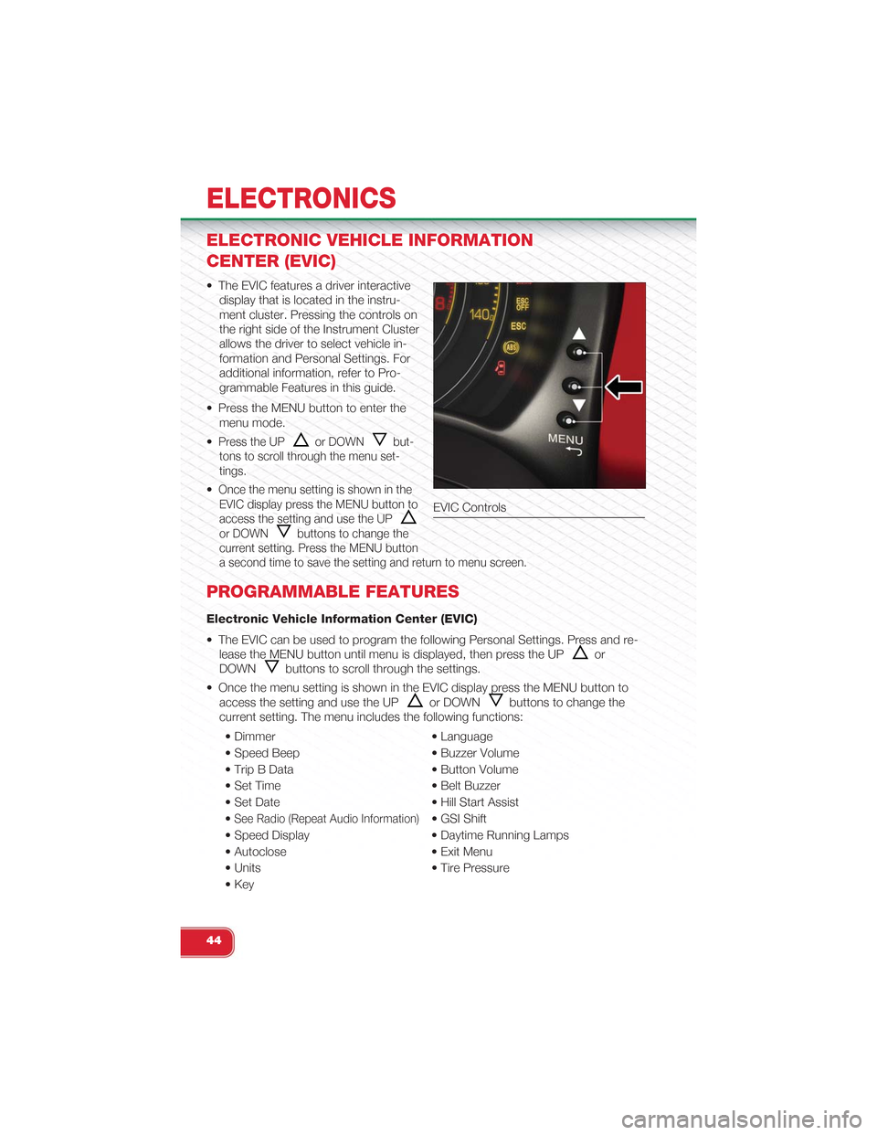
• The EVIC features a driver interactive
display that is located in the instru-
ment cluster. Pressing the controls on
the right side of the Instrument Cluster
allows the driver to select vehicle in-
formation and Personal Settings. For
additional information, refer to Pro-
grammable Features in this guide.
• Press the MENU button to enter the
menu mode.
•Press the UPor DOWNbut-
tons to scroll through the menu set-
tings.
•Once the menu setting is shown in the
EVIC display press the MENU button to
access the setting and use the UP
or DOWNbuttons to change the
current setting. Press the MENU button
a second time to save the setting and return to menu screen.
PROGRAMMABLE FEATURES
Electronic Vehicle Information Center (EVIC)
• The EVIC can be used to program the following Personal Settings. Press and re-
lease the MENU button until menu is displayed, then press the UPor
DOWNbuttons to scroll through the settings.
• Once the menu setting is shown in the EVIC display press the MENU button to
access the setting and use the UPor DOWNbuttons to change the
current setting. The menu includes the following functions:
• Dimmer • Language
• Speed Beep • Buzzer Volume
• Trip B Data • Button Volume
• Set Time • Belt Buzzer
• Set Date • Hill Start Assist
•See Radio (Repeat Audio Information)• GSI Shift
• Speed Display • Daytime Running Lamps
• Autoclose • Exit Menu
• Units • Tire Pressure
• Key
EVIC Controls
ELECTRONICS
44
Page 51 of 88
- Electronic Throttle Control (ETC) Light
•This light informs you of a problem with the Electronic Throttle Control (ETC) system.
• If a problem is detected, the light will come on while the engine is running. Cycle
the ignition when the vehicle has completely stopped; the light should turn off.
• If the light remains lit with the engine running, your vehicle will usually be drivable;
however, see an authorized service center immediately. If the light is flashing
when the engine is running, immediate service is required and you may experi-
ence reduced performance, an elevated/rough idle or engine stall and your ve-
hicle may require towing.
- Electronic Stability Control (ESC) OFF Indicator Light
• This light indicates the ESC system has been turned off by the driver.
Partial Off
This mode is entered by momentarily pressing the ESC Off switch. This mode is intended
for times when a more spirited driving experience is desired. It is also intended for driving
in deep snow, sand or gravel conditions, when more wheel spin than ESC would nor-
mally allow is required to gain traction. To turn ESC on again, momentarily press the
switch again. This will restore the normal ESC On mode of operation.
Full Off
This mode is intended for off-highway or off-road use only and should not be used on
public roadways. In this mode, all TCS and ESC stability features are turned OFF, ex-
cept for the limited slip feature described in the TCS section. To enter the “Full Off”
mode, depress and hold the ESC OFF switch for five seconds. After five seconds, the
ESC OFF Indicator Light will illuminate, and the “ESC OFF” message will display in the
EVIC. To turn ESC ON again, momentarily press the ESC OFF switch.
- Electronic Stability Control (ESC) Activation / Malfunction
Indicator Light
• The “ESC Activation/Malfunction Indicator Light” in the instrument cluster will
come on for four seconds when the ignition switch is turned to the ON/RUN posi-
tion. If the “ESC Activation/Malfunction Indicator Light” comes on continuously
with the engine running, a malfunction has been detected in the ESC system. If
this light remains on, see your authorized dealer as soon as possible to have the
problem diagnosed and corrected.
NOTE:
• The “ESC Off Indicator Light” and the “ESC Activation/Malfunction Indicator
Light” come on momentarily each time the ignition switch is turned to ON/RUN.
• Each time the ignition is turned to ON/RUN, the ESC system will be ON even if it
was turned off previously.
• ESC Activation/Malfunction Light can blink during a ESC or TC intervention.
WHAT TO DO IN EMERGENCIES
49
Page 52 of 88
TTC (Torque Transfer Control)
• The TTC system uses the brakes to prevent unwanted wheelspin during corner-
ing, to maximize acceleration and minimize understeering during aggressive driv-
ing. This feature is active in all modes. While TTC is active, the “ESC” lamp in the
instrument cluster may flash.
- Tire Pressure Monitoring System (TPMS) Light
• Each tire, including the spare (if provided), should be checked monthly when cold
and inflated to the inflation pressure recommended by the vehicle manufacturer
on the vehicle placard or tire inflation pressure label. (If your vehicle has tires of a
different size than the size indicated on the vehicle placard or tire inflation pres-
sure label, you should determine the proper tire inflation pressure for those tires.)
• As an added safety feature, your vehicle has been equipped with a Tire Pressure
Monitoring System (TPMS) that illuminates a low tire pressure telltale when one or
more of your tires is significantly under-inflated. Accordingly, when the low tire
pressure telltale illuminates, you should stop and check your tires as soon as
possible, and inflate them to the proper pressure. Driving on a significantly under-
inflated tire causes the tire to overheat and can lead to tire failure. Under-inflation
also reduces fuel efficiency and tire tread life, and may affect the vehicle’s han-
dling and stopping ability.
•IF THE LIGHT STARTS FLASHING INDICATING A LOW TIRE PRES-
SURE, ADJUST THE AIR PRESSURE IN THE LOW TIRE TO THE AIR
PRESSURE SHOWN ON THE VEHICLE PLACARD OR TIRE INFLATION
PRESSURE LABEL LOCATED ON THE DRIVER'S DOOR. NOTE: AFTER
INFLATION, THE VEHICLE MAY NEED TO BE DRIVEN FOR 20 MIN-
UTES BEFORE THE FLASHING LIGHT WILL TURN OFF.
•Please note that the TPMS is not a substitute for proper tire maintenance, and it is
the driver’s responsibility to maintain correct tire pressure, even if under-inflation has
not reached the level to trigger illumination of the TPMS low tire pressure telltale.
• Your vehicle has also been equipped with a TPMS malfunction indicator to indi-
cate when the system is not operating properly. The TPMS malfunction indicator
is combined with the low tire pressure telltale. When the system detects a mal-
function, the telltale will flash for approximately one minute and then remain con-
tinuously illuminated. This sequence will continue upon subsequent vehicle start-
ups as long as the malfunction exists.
• When the malfunction indicator is illuminated, the system may not be able to de-
tect or signal low tire pressure as intended. TPMS malfunctions may occur for a
variety of reasons, including the installation of replacement or alternate tires or
wheels on the vehicle that prevent the TPMS from functioning properly. Always
check the TPMS malfunction telltale after replacing one or more tires or wheels
on your vehicle, to ensure that the replacement or alternate tires and wheels al-
low the TPMS to continue to function properly.
WHAT TO DO IN EMERGENCIES
50
Page 55 of 88
IF YOUR ENGINE OVERHEATS
• In any of the following situations, you can reduce the potential for overheating by
taking the appropriate action.
• On the highways — slow down.
• In city traffic — while stopped, shift transmission into NEUTRAL, but do not in-
crease engine idle speed.
NOTE:There are steps that you can take to slow down an overheat condition:
• If your air conditioner (A/C) is on, turn it off. The A/C system adds heat to the en-
gine cooling system and turning the A/C off can help remove this heat.
• You can also turn the Temperature control to maximum heat, the Mode control to
floor and the Fan control to high. This allows the heater core to act as a supple-
ment to the radiator and aids in removing heat from the engine cooling system.
• If the temperature reading does not return to normal, turn the engine off immedi-
ately.
• We recommend that you do not operate the vehicle or engine damage will occur.
Have the vehicle serviced immediately.
CAUTION!
Driving with a hot cooling system could damage your vehicle. If the temperature
gauge reads hot, pull over and stop the vehicle. Idle the vehicle with the air condi-
tioner turned off until the pointer drops back into the normal range. If the pointer
remains on hot, turn the engine off immediately and call for service.
WARNING!
You or others can be badly burned by hot engine coolant (antifreeze) or steam
from your radiator. If you see or hear steam coming from under the hood, do not
open the hood until the radiator has had time to cool. Never try to open a cooling
system pressure cap when the radiator or coolant bottle is hot.
WHAT TO DO IN EMERGENCIES
53