brakes FIAT 500 ABARTH CABRIO 2017 2.G Owners Manual
[x] Cancel search | Manufacturer: FIAT, Model Year: 2017, Model line: 500 ABARTH CABRIO, Model: FIAT 500 ABARTH CABRIO 2017 2.GPages: 338, PDF Size: 2.78 MB
Page 136 of 338
Anti-Lock Brake (ABS) Indicator Light
Yellow TelltaleLight What It Means
Anti-Lock Brake (ABS) Indicator Light
After the ignition is turned on, the Anti-Lock Brake System (ABS) light illuminates to indi-
cate function check at vehicle startup. If the light remains on after startup or comes on and
stays on at road speeds, it may indicate that the ABS has detected a malfunction or has be-
come inoperative. The system reverts to standard non-anti-lock brakes.
If both the Brake Warning Light and the ABS Warning Light are on, see an authorized
dealer immediately. Refer to “Anti-Lock Brake System” in “Starting And Operating” for fur-
ther information.
Generic Warning Indicator Light
Yellow Telltale
Light What It Means
Generic Warning Indicator Light
The Generic Warning Light will illuminate if any of the following conditions occur: Oil
Change Request, Engine Oil Pressure Sensor Failure, External Light Failure, Fuel Cut-Off
Not Available, Parking Sensor Failure, DST System Failure.
134 UNDERSTANDING YOUR INSTRUMENT PANEL
Page 192 of 338
Key Ignition Park Interlock
This vehicle is equipped with a Key Ignition Park
Interlock which requires the transmission to be in PARK
before the ignition can be turned to the LOCK/OFF
(key removal) position. The key can only be removed
from the ignition when the ignition is in the LOCK/OFF
position, and once removed, the transmission is locked
in PARK.
Brake/Transmission Shift Interlock System
This vehicle is equipped with a Brake Transmission
Shift Interlock System (BTSI) that holds the transmis-
sion gear selector in PARK unless the brakes are ap-
plied. To shift the transmission out of PARK, the igni-
tion must be turned to the ON/RUN mode (engine
running or not) and the brake pedal must be pressed.
Six-Speed Automatic Transmission
The transmission gear position display (located in the
instrument cluster) indicates the transmission gear
range. You must press the brake pedal to move the gear
selector out of PARK (Refer to “Brake/Transmission
Shift Interlock System” in this section). To drive, move
the gear selector from PARK or NEUTRAL to the
DRIVE position.The electronically-controlled transmission provides a
precise shift schedule. The transmission electronics are
self-calibrating; therefore, the first few shifts on a new
vehicle may be somewhat abrupt. This is a normal
condition, and precision shifts will develop within a
few hundred miles (kilometers).
Only shift from DRIVE to PARK or REVERSE when the
accelerator pedal is released and the vehicle is stopped.
Be sure to keep your foot on the brake pedal when
shifting between these gears.
The transmission gear selector has PARK, REVERSE,
NEUTRAL, DRIVE, and AutoStick (+/–) shift positions.Gear Selector
190 STARTING AND OPERATING
Page 200 of 338
Shallow Standing Water
Although your vehicle is capable of driving through
shallow standing water, consider the following Cau-
tions and Warnings before doing so.
WARNING!
•Driving through standing water limits your vehi-
cle’s traction capabilities. Do not exceed 5 mph
(8 km/h) when driving through standing water.
• Driving through standing water limits your vehi-
cle’s braking capabilities, which increases stop-
ping distances. Therefore, after driving through
standing water, drive slowly and lightly press on
the brake pedal several times to dry the brakes.
•
Failure to follow these warnings may result in inju-
ries that are serious or fatal to you, your passengers,
and others around you.
CAUTION!
• Always check the depth of the standing water
before driving through it. Never drive through
standing water that is deeper than the bottom of
the tire rims mounted on the vehicle.
•
Determine the condition of the road or the path that
is under water and if there are any obstacles in the
way before driving through the standing water.
•Do not exceed 5 mph (8 km/h) when driving through
standing water. This will minimize wave effects.
• Driving through standing water may cause dam-
age to your vehicle’s drivetrain components. Al-
ways inspect your vehicle’s fluids (i.e., engine oil,
transmission, axle, etc.) for signs of contamination
(i.e., fluid that is milky or foamy in appearance)
after driving through standing water. Do not
continue to operate the vehicle if any fluid ap-
pears contaminated, as this may result in further
damage. Such damage is not covered by the New
Vehicle Limited Warranty.
•
Getting water inside your vehicle’s engine can
cause it to lock up and stall out, and cause serious
internal damage to the engine. Such damage is not
covered by the New Vehicle Limited Warranty.
198 STARTING AND OPERATING
Page 204 of 338
Automatic Transmission — If Equipped
The Sport mode increases steering feedback to the driver
with slight increase in effort and changes the transmission
shift schedules for more aggressive shifting. This driving
mode is useful while driving on twisty roads where more
steering precision is desired in spirited cornering.
1. To activate the Sport mode, push the SPORT button.Once activated, a SPORT message will be displayed in
the instrument cluster.
2. Push the SPORT button again to return to the stan-
dard driving mode.
BRAKE SYSTEM
Your vehicle is equipped with dual hydraulic brake
systems. If either of the two hydraulic systems loses
normal capability, the remaining system will still func-
tion. However, there will be some loss of overall brak-
ing effectiveness. You may notice increased pedal travel
during application, greater pedal force required to slow
or stop, and potential activation of the “Brake System
Warning Light”.
In the event power assist is lost for any reason (i.e.,
repeated brake applications with the engine off), the
brakes will still function. However, the effort required
to brake the vehicle will be much greater than that
required with the power system operating.
SPORT Button
202 STARTING AND OPERATING
Page 205 of 338
ELECTRONIC BRAKE CONTROL SYSTEM
Your vehicle is equipped with a advanced electronic
brake control system that includes the Anti-Lock Brake
System (ABS), Brake Assist System (BAS), Traction
Control System (TCS), Hill Start Assist (HSA), and
Electronic Stability Control (ESC). All systems work
together to enhance vehicle stability and control in
various driving conditions and are commonly referred
to as ESC.
Four-Wheel Anti-Lock Brake System (ABS)
The Four-Wheel ABS is designed to aid the driver in
maintaining vehicle control under adverse braking con-
ditions. The system operates with a separate computer
to modulate hydraulic pressure, to prevent wheel
lock-up and to help avoid skidding on slippery sur-
faces.
The system’s pump motor runs during an ABS stop to
provide regulated hydraulic pressure. The pump motor
makes a low humming noise during operation, which is
normal.
The ABS includes an amber ABS Warning Light. When
the light is illuminated, the ABS is not functioning. Thesystem reverts to standard non-anti-lock brakes. Turn-
ing the ignition Off and On again may reset the ABS if
the fault detected was only momentary.
WARNING!
•
Pumping the Anti-Lock Brakes will diminish
their effectiveness and may lead to a collision.
Pumping makes the stopping distance longer. Just
press firmly on your brake pedal when you need
to slow down or stop.
• The Anti-Lock Brake System (ABS) cannot pre-
vent the natural laws of physics from acting on
the vehicle, nor can it increase braking or steering
efficiency beyond that afforded by the condition
of the vehicle brakes and tires or the traction
afforded.
• The ABS cannot prevent collisions, including
those resulting from excessive speed in turns,
following another vehicle too closely, or hydro-
planing.
• The capabilities of an ABS-equipped vehicle
must never be exploited in a reckless or danger-
ous manner, which could jeopardize the user’s
safety or the safety of others.
5
STARTING AND OPERATING 203
Page 206 of 338
When you are in a severe braking condition involving
the use of the ABS, you will experience some pedal drop
as the vehicle comes to a stop. This is the result of the
system reverting to the base brake system.
Engagement of the ABS may be accompanied by a
pulsing sensation. You may also hear a clicking noise.
These occurrences are normal and indicate that the
system is functioning properly.
Brake Assist System (BAS)
The BAS is designed to optimize the vehicle’s braking
capability during emergency braking maneuvers. The
system detects an emergency braking situation by sens-
ing the rate and amount of brake application and then
applies optimum pressure to the brakes. This can help
reduce braking distances. The BAS complements the
Anti-Lock Brake System (ABS). Applying the brakes
very quickly results in the best BAS assistance. To
receive the benefit of the system, you must apply
continuousbraking pressure during the stopping se-
quence (do not “pump” the brakes). Do not reduce
brake pedal pressure unless braking is no longer de-
sired. Once the brake pedal is released, the BAS is
deactivated.
WARNING!
• The Brake Assist System (BAS) cannot prevent
the natural laws of physics from acting on the
vehicle, nor can it increase the traction afforded
by prevailing road conditions.
•
The BAS cannot prevent collisions, including those
resulting from excessive speed in turns, driving on
very slippery surfaces, or hydroplaning.
• The capabilities of a BAS-equipped vehicle must
never be exploited in a reckless or dangerous
manner which could jeopardize the user ’s safety
or the safety of others.
Traction Control System (TCS)
The Traction Control System (TCS) monitors the
amount of wheel spin of each of the driven wheels. If
wheel spin is detected, brake pressure is applied to the
slipping wheel(s) and engine power is reduced to
provide enhanced acceleration and stability. A feature of
the TCS system, Brake Limited Differential (BLD), func-
tions similar to a limited slip differential and controls
the wheel spin across a driven axle. If one wheel on a
driven axle is spinning faster than the other, the system
will apply the brake of the spinning wheel. This will
204 STARTING AND OPERATING
Page 292 of 338
Brake System
In order to assure brake system performance, all brake
system components should be inspected periodically.
Refer to the “Maintenance Schedule” for the proper
maintenance intervals.
WARNING!
Riding the brakes can lead to brake failure and possi-
bly a collision. Driving with your foot resting or riding
on the brake pedal can result in abnormally high brake
temperatures, excessive lining wear, and possible
brake damage. Riding the brakes may also reduce
braking capacity in an emergency.
Brake Master Cylinder
The fluid level in the master cylinder should be checked
when performing under hood services, or immediately
if the “Brake Warning Light” is on.
Be sure to clean the top of the master cylinder area
before removing the cap. If necessary, add fluid to bringthe fluid level up to the requirements described on the
brake fluid reservoir. Fluid level can be expected to fall
as the brake pads wear. The brake fluid level should be
checked when the pads are replaced. However, low
fluid level may be caused by a leak and a checkup may
be needed.
NOTE:
If your vehicle is equipped with a manual
transmission, the brake fluid reservoir supplies fluid to
both the brake system and the clutch release system.
The two systems are separated in the reservoir, and a
leak in one system will not affect the other system. The
manual transmission clutch release system should not
require fluid replacement during the life of the vehicle.
If the brake fluid reservoir is low and the brake system
does not indicate any leaks or other problems, it may be
a result of a leak in the hydraulic clutch release system.
See your local authorized dealer for service.
290 MAINTAINING YOUR VEHICLE
Page 327 of 338
Battery........................... .123, 276
Charging System Light ..................123
Jump Starting ........................ .259
Keyless Key Fob Replacement ..............15
Belts, Seat ..............................61
Body Mechanism Lubrication ................281
B-Pillar Location ........................ .215
Brake Assist System ..................... .204
Brake Fluid ........................ .308, 310
Brake, Parking ......................... .200
Brakes ............................... .290
Brake System ....................... .202, 290
Anti-Lock (ABS) ...................... .203
Master Cylinder ...................... .290
Parking ............................ .200
Warning Light ....................... .121
Brake/Transmission Interlock ................190
Bulb Replacement .....................304, 305
Bulbs, Light ......................... .64, 304
Capacities, Antifreeze (Engine Coolant) .........308
Capacities, Fluid ........................ .308
Caps, Filler Fuel ............................... .242
Oil (Engine) ......................... .275Carbon Monoxide Warning
...............61, 242
Cargo Area Features ..................... .102
Car Washes ........................... .294
Cellular Phone ......................... .167
Chains, Tire ........................... .230
Chart, Tire Sizing ........................211
Check Engine Light (Malfunction Indicator Light) .271
Checking Your Vehicle For Safety ..............60
Checks, Safety ...........................60
Child Restraint ...........................44
Child Restraints Booster Seats ..........................48
Child Restraints ........................44
Child Seat Installation ....................57
How To Stow An Unused ALR Seat Belt .......54
Infants And Child Restraints ...............46
Lower
Anchors And Tethers For Children ......50
Older Children And Child Restraints .........46
Seating Positions .......................49
Clean Air Gasoline ...................... .239
Cleaning Wheels ............................ .295
Climate Control ........................ .167
Manual ............................ .167
Clutch ............................... .29010
INDEX 325
Page 332 of 338
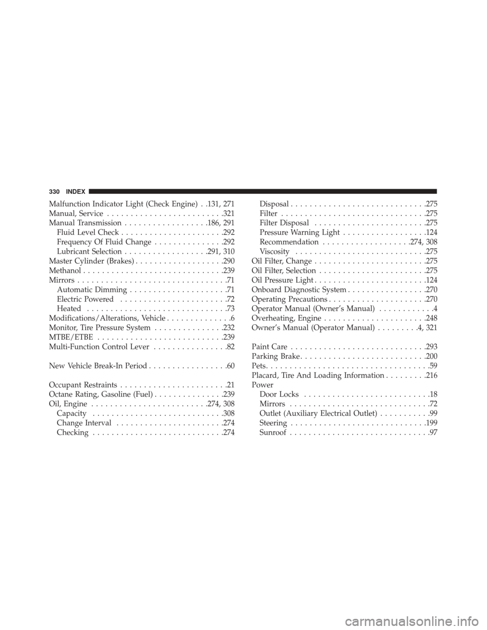
Malfunction Indicator Light (Check Engine) . .131, 271
Manual, Service........................ .321
Manual Transmission ..................186, 291
Fluid Level Check ..................... .292
Frequency Of Fluid Change ...............292
Lubricant Selection ..................291, 310
Master Cylinder (Brakes) ...................290
Methanol ............................. .239
Mirrors ................................71
Automatic Dimming .....................71
Electric Powered .......................72
Heated ..............................73
Modifications/Alterations, Vehicle ..............6
Monitor, Tire Pressure System ...............232
MTBE/ETBE .......................... .239
Multi-Function Control Lever ................82
New Vehicle Break-In Period .................60
Occupant Restraints .......................21
Octane Rating, Gasoline (Fuel) ...............239
Oil, Engine ........................ .274, 308
Capacity ........................... .308
Change Interval ...................... .274
Checking ........................... .274Disposal
............................ .275
Filter .............................. .275
Filter Disposal ....................... .275
Pressure Warning Light ..................124
Recommendation ...................274, 308
Viscosity ........................... .275
Oil Filter, Change ....................... .275
Oil Filter, Selection ...................... .275
Oil Pressure Light ....................... .124
Onboard Diagnostic System .................270
Operating Precautions .....................270
Operator Manual (Owner’s Manual) ............4
Overheating, Engine ..................... .248
Owner’s Manual (Operator Manual) .........4,321
Paint Care ............................ .293
Parking
Brake .......................... .200
Pets ...................................59
Placard, Tire And Loading Information .........216
Power Door Locks ...........................18
Mirrors ..............................72
Outlet (Auxiliary Electrical Outlet) ...........99
Steering ............................ .199
Sunroof ..............................97
330 INDEX