battery FIAT 500E 2014 2.G Owner's Manual
[x] Cancel search | Manufacturer: FIAT, Model Year: 2014, Model line: 500E, Model: FIAT 500E 2014 2.GPages: 92, PDF Size: 3.24 MB
Page 20 of 92
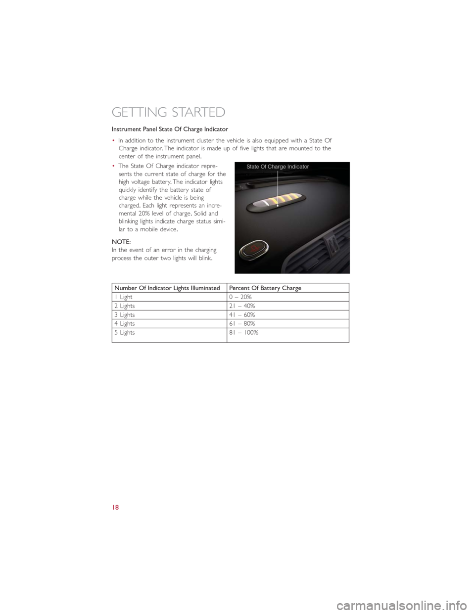
Instrument Panel State Of Charge Indicator
•In addition to the instrument cluster the vehicle is also equipped with a State Of
Charge indicator.The indicator is made up of five lights that are mounted to the
center of the instrument panel.
•The State Of Charge indicator repre-
sents the current state of charge for the
high voltage battery.The indicator lights
quickly identify the battery state of
charge while the vehicle is being
charged.Each light represents an incre-
mental 20% level of charge.Solid and
blinking lights indicate charge status simi-
lar to a mobile device.
NOTE:
In the event of an error in the charging
process the outer two lights will blink.
Number Of Indicator Lights Illuminated Percent Of Battery Charge
1 Light 0 – 20%
2 Lights 21 – 40%
3 Lights 41 – 60%
4 Lights 61 – 80%
5 Lights 81 – 100%
GETTING STARTED
18
Page 23 of 92
VEHICLE SECURITY ALARM
This Vehicle Security Alarm monitors the doors, liftgate, and ignition switch for unauthor-
ized operation.
When the alarm is activated, the interior switches for door locks are disabled.The Vehicle
Security Alarm provides both audio and visual signals repeatedly for three minutes.If the
disturbance is still present (driver's door, passenger door, other doors, ignition) after three
minutes, the parking lights and tail lights will flash for an additional 15 minutes.
To Arm:
•Press the Key Fob LOCK button.
To Disarm The System:
•Push the Key Fob UNLOCK button or cycle the ignition to the ON/RUN position.
The Vehicle Security Alarm is designed to protect your vehicle; however, you can create
conditions where the Vehicle Security Alarm will give you a false alarm.If one of the pre-
viously described arming sequences has occurred, the Vehicle Security Alarm will arm re-
gardless of whether you are in the vehicle or not.If you remain in the vehicle and open
a door, the alarm will sound.If this occurs, disarm the Vehicle Security Alarm.
If the Vehicle Security Alarm is armed and the battery becomes disconnected the Vehicle
Security Alarm will remain armed when the battery is reconnected.The exterior lights
will flash, and the horn will sound.If this occurs, disarm the Vehicle Security Alarm.
POWER DOOR LOCKS
•The vehicles power door locks are activated by moving the inside door handles.
•Push or pull the driver’s door handle to lock or unlock the doors and liftgate when
the doors are closed.
SEAT BELT
Be sure everyone in your vehicle is in a seat and using a seat belt properly.
•Position the lap belt across your thighs, below your abdomen.To remove slack in the
lap portion, pull up a bit on the shoulder belt.To loosen the lap belt if it is too tight,
tilt the latch plate and pull on the lap belt.A snug belt reduces the risk of sliding
under the belt in a collision.
•Position the shoulder belt on your chest so that it is comfortable and not resting on
your neck.The retractor will withdraw any slack in the belt.
A shoulder belt placed behind you will not protect you from injury during a collision.
You are more likely to hit your head in a collision if you do not wear your shoulder belt.
The lap and shoulder belt are meant to be used together.
A belt that is too loose will not protect you properly.In a sudden stop you could move
too far forward, increasing the possibility of injury.Wear your seat belt snugly.
GETTING STARTED
21
Page 35 of 92
EXTENDING YOUR DRIVING RANGE PER CHARGE
•A little knowledge will go a long way to extend your driving range on the 500e.First
and foremost understand that the drive system and cabin temperature management
features use the most energy from the high voltage battery.Reducing energy draw
from these features are the easiest and most effective way to extend driving range.
•Just like a conventional vehicle, 500e likes to keeps things smooth and steady for most
efficient operation.When driving, avoid aggressive driving styles and high speeds for
extended times.When practical, choose surface streets over the highway, work to
maintain a steady speed to extend range.
•The 500e uses high voltage components to heat and cool the cabin, so a little aware-
ness can go a long way to extend range.When using automatic climate control, con-
sider setting temperatures a few degrees higher or lower during hot and cold days.
If your 500e has been soaking in hot or cold temperatures for an extended period, it
is recommended that the car be preconditioned via the mobile application while still
plugged into a charging source.This will allow 500e to use external power to establish
a comfortable cabin temperature before the drive, and allow the battery to maintain
the temperature using significantly less energy.
Additional Tips:
•Keep tires properly inflated
•Avoid carrying nonessential cargo
•Be mindful of adding external accessories that may increase aerodynamic drag
•Perform all scheduled maintenance at recommended intervals
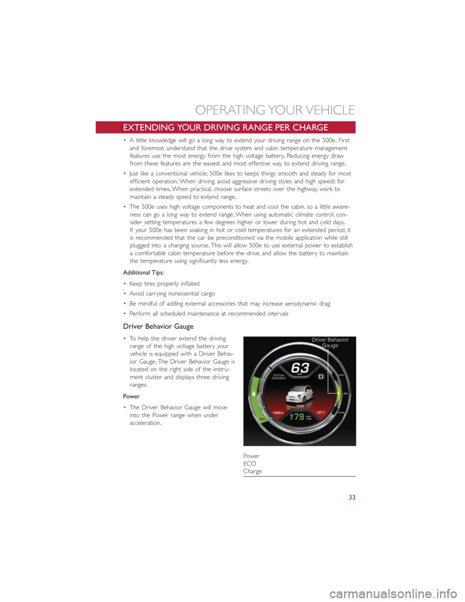
Driver Behavior Gauge
•To help the driver extend the driving
range of the high voltage battery your
vehicle is equipped with a Driver Behav-
ior Gauge.The Driver Behavior Gauge is
located on the right side of the instru-
ment cluster and displays three driving
ranges:
Power
•The Driver Behavior Gauge will move
into the Power range when under
acceleration.
Power
ECO
Charge
OPERATING YOUR VEHICLE
33
Page 36 of 92
ECO
•The Driver Behavior Gauge will move into the ECO range when you are maximizing
the driving range of the high voltage battery.
Charge
•The Driver Behavior Gauge will move into the Charge range when battery regenera-
tion is active (either coasting or braking).
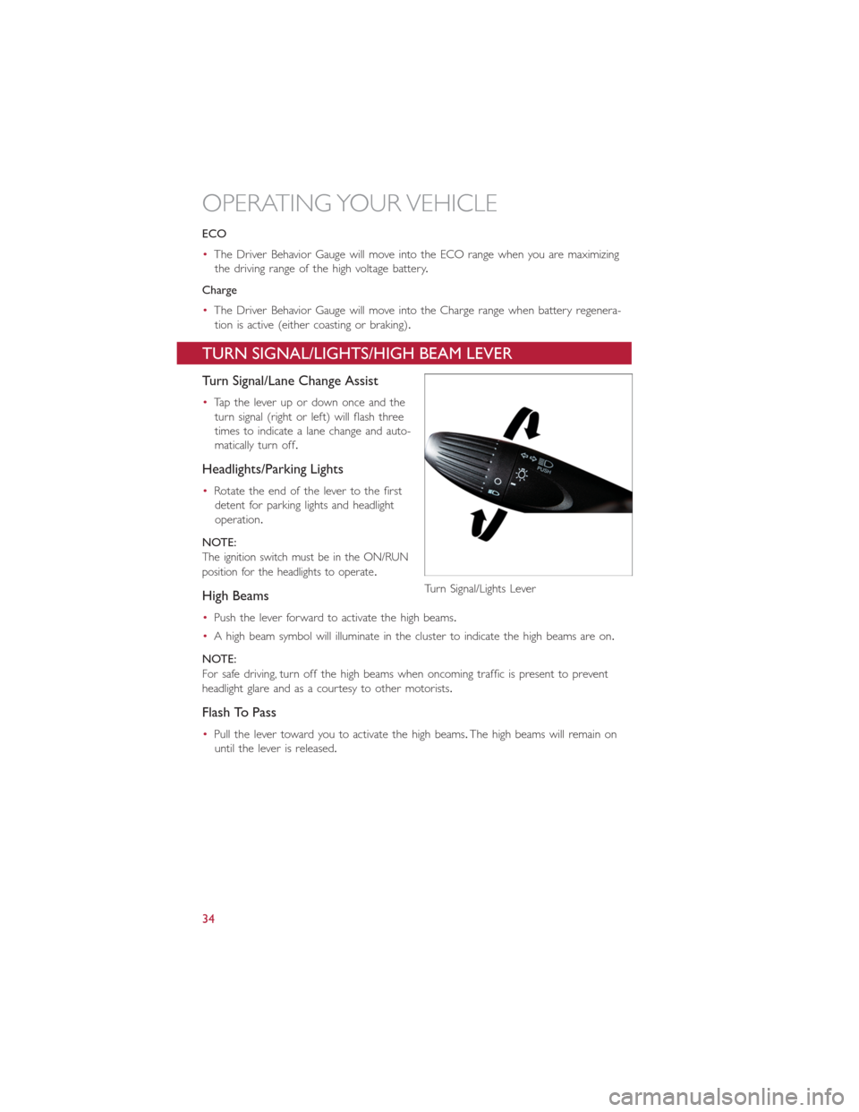
TURN SIGNAL/LIGHTS/HIGH BEAM LEVER
Turn Signal/Lane Change Assist
•Tap the lever up or down once and the
turn signal (right or left) will flash three
times to indicate a lane change and auto-
matically turn off.
Headlights/Parking Lights
•Rotate the end of the lever to the first
detent for parking lights and headlight
operation.
NOTE:
The ignition switch must be in the ON/RUN
position for the headlights to operate.
High Beams
•Push the lever forward to activate the high beams.
•A high beam symbol will illuminate in the cluster to indicate the high beams are on.
NOTE:
For safe driving, turn off the high beams when oncoming traffic is present to prevent
headlight glare and as a courtesy to other motorists.
Flash To Pass
•Pull the lever toward you to activate the high beams.The high beams will remain on
until the lever is released.
Turn Signal/Lights Lever
OPERATING YOUR VEHICLE
34
Page 53 of 92
iPod®/USB/MP3 CONTROL
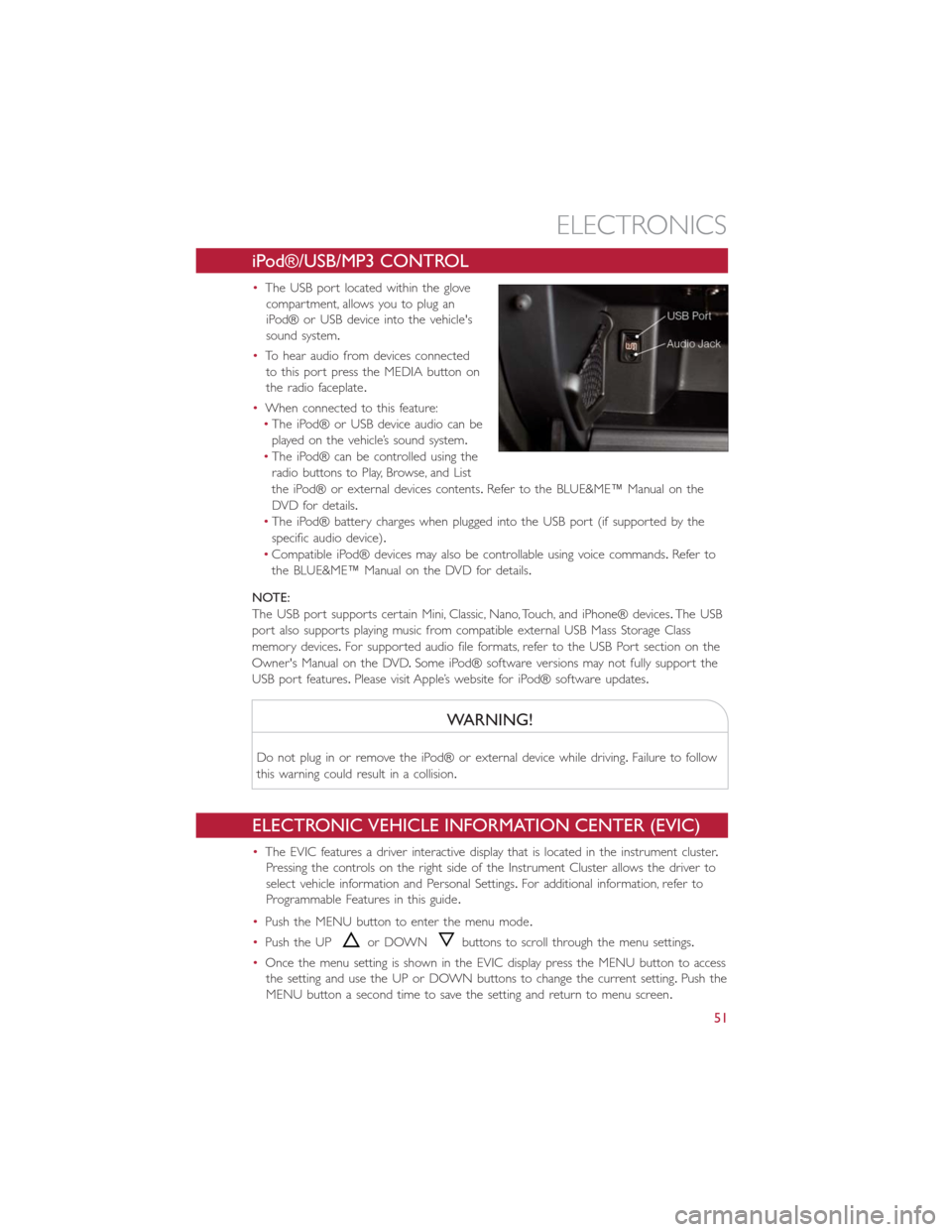
•The USB port located within the glove
compartment, allows you to plug an
iPod® or USB device into the vehicle's
sound system.
•To hear audio from devices connected
to this port press the MEDIA button on
the radio faceplate.
•When connected to this feature:
•The iPod® or USB device audio can be
played on the vehicle’s sound system.
•The iPod® can be controlled using the
radio buttons to Play, Browse, and List
the iPod® or external devices contents.Refer to the BLUE&ME™ Manual on the
DVD for details.
•The iPod® battery charges when plugged into the USB port (if supported by the
specific audio device).
•Compatible iPod® devices may also be controllable using voice commands.Refer to
the BLUE&ME™ Manual on the DVD for details.
NOTE:
The USB port supports certain Mini, Classic, Nano, Touch, and iPhone® devices.The USB
port also supports playing music from compatible external USB Mass Storage Class
memory devices.For supported audio file formats, refer to the USB Port section on the
Owner's Manual on the DVD.Some iPod® software versions may not fully support the
USB port features.Please visit Apple’s website for iPod® software updates.
WARNING!
Do not plug in or remove the iPod® or external device while driving.Failure to follow
this warning could result in a collision.
ELECTRONIC VEHICLE INFORMATION CENTER (EVIC)
•The EVIC features a driver interactive display that is located in the instrument cluster.
Pressing the controls on the right side of the Instrument Cluster allows the driver to
select vehicle information and Personal Settings.For additional information, refer to
Programmable Features in this guide.
•Push the MENU button to enter the menu mode.
•Push the UP
or DOWNbuttons to scroll through the menu settings.
•Once the menu setting is shown in the EVIC display press the MENU button to access
the setting and use the UP or DOWN buttons to change the current setting.Push the
MENU button a second time to save the setting and return to menu screen.
ELECTRONICS
51
Page 54 of 92
PROGRAMMABLE FEATURES
Electronic Vehicle Information Center (EVIC)
•Push the MENU button to enter the menu mode.
•Push the UP
or DOWNbuttons to scroll through the menu settings.
•Once the menu setting is shown in the EVIC display press the MENU button to access
the setting and use the UP or DOWN buttons to change the current setting.Push the
MENU button a second time to save the setting and return to menu screen.
•Charging Schedule•Daytime Running Lights
•Set Date•Button Volume
•Set Time•Hill Start Assist
•Units•Stored Warning
•Languages•Tutorial
•Audio Display•Connectivity ID
•Battery % Display•Restore Factory Settings
•Auto Door Lock•Exit Menu
•Remote Unlock
Selecting An Option Of The Main Menu Without Submenu:
•Briefly push the MENU button to select the main menu option to set.
•Push the UP or DOWN button to select the new setting.
•Briefly press the MENU button to store the new setting and go back to the main
menu option previously selected.
Selecting An Option Of The Main Menu With Submenu:
•Briefly push the MENU button to display the first submenu option.
•Push the UP or DOWN button to scroll through all the submenu options.
•Briefly press the MENU button to select the displayed submenu option and to open
the relevant setup menu.
•Push the UP or DOWN button to select the new setting for this submenu option.
•Briefly press the MENU button to store the new setting and go back to the previously
selected submenu option.
•Push and hold the MENU button to return to the main menu (short hold) or the
main screen (longer hold).
NOTE:
The charging schedule is based on the date and time programmed in the EVIC.
ELECTRONICS
52
Page 67 of 92
WARNING!
•Do not attempt to seal a tire on the side of the vehicle closest to traffic.Pull far
enough off the road to avoid the danger of being hit when using the TIREFIT kit.
•Do not use TIREFIT or drive the vehicle under the following circumstances:
•If the puncture in the tire tread is approximately 1/4”.(6 mm) or larger.
•If the tire has any sidewall damage.
•If the tire has any damage from driving with extremely low tire pressure.
•If the tire has any damage from driving on a flat tire.
•If the wheel has any damage.
•If you are unsure of the condition of the tire or the wheel.
•Keep TIREFIT away from open flames or heat source.
•A loose TIREFIT kit thrown forward in a collision or hard stop could endanger the
occupants of the vehicle.Always stow the TIREFIT kit in the place provided.Failure
to follow these warnings can result in injuries that are serious or fatal to you, your
passengers, and others around you.
•Take care not to allow the contents of TIREFIT to come in contact with hair, eyes,
or clothing.TIREFIT is harmful if inhaled, swallowed, or absorbed through the skin.
It causes skin, eye, and respiratory irritation.Flush immediately with plenty of water
if there is any contact with eyes or skin.Change clothing as soon as possible, if
there is any contact with clothing.
•TIREFIT Sealant solution contains latex.In case of an allergic reaction or rash, con-
sult a physician immediately.Keep TIREFIT out of reach of children.If swallowed,
rinse mouth immediately with plenty of water and drink plenty of water.Do not
induce vomiting! Consult a physician immediately.
•TIREFIT is not a permanent flat tire repair.Have the tire inspected and repaired
or replaced after using TIREFIT.Do not exceed 55 mph (88 km/h) until the tire is
repaired or replaced.Failure to follow this warning can result in injuries that are
serious or fatal to you, your passengers, and others around you.
JUMP-STARTING PROCEDURE — 12 VOLT BATTERY
•If your vehicle has a discharged 12 Volt battery, it can be jump-started using a set of
jumper cables and a battery in another vehicle or by using a portable battery booster
pack.Jump-starting can be dangerous if done improperly so please follow the proce-
dures in this section carefully.
NOTE:
When using a portable battery booster pack, follow the manufacturer’s operating instruc-
tions and precautions.
WHAT TO DO IN EMERGENCIES
65
Page 68 of 92
Preparations For Jump-Start
•The battery in your vehicle is located in the underhood compartment under the
beauty cover.
1.Set the parking brake, place the transmission into PARK and turn the ignition to OFF/
LOCK.
2.Turn off the heater, radio, and all unnecessary electrical accessories.
3.If using another vehicle to jump-start the battery, park the vehicle within the jumper
cables reach, set the parking brake and make sure the ignition is OFF.
Jump-Starting Procedure
1.Connect the positive(+)end of the jumper cable to the positive(+)post of the dis-
charged vehicle.
2.Connect the opposite end of the positive(+)jumper cable to the positive(+)post of
the booster battery.
3.Connect the negative end(-)of the jumper cable to the negative(-)post of the
booster battery.
4.Connect the opposite end of the negative(-)jumper cable to a good ground (ex-
posed metal part of the discharged vehicle) away from the battery and the high volt-
age cables.
5.Start the engine in the vehicle that has the booster battery, let the engine idle a few
minutes, and then start the the vehicle with the discharged battery.
•Once the vehicle has started, remove the jumper cables in the reverse sequence:
1.Disconnect the negative(-)jumper cable from the ground(-)of the vehicle with the
discharged battery.
2.Disconnect the negative end(-)of the jumper cable from the negative(-)post of the
booster battery.
3.Disconnect the opposite end of the positive(+)jumper cable from the positive(+)
post of the booster battery.
4.Disconnect the positive(+)end of the jumper cable from the positive(+)post of the
discharged vehicle.
•If frequent jump-starting is required to start your vehicle, you should have the battery
and charging system inspected at your authorized dealer.
WHAT TO DO IN EMERGENCIES
66
Page 69 of 92
CAUTION!
•Accessories that can be plugged into the vehicle power outlets draw power from
the vehicle’s battery, even when not in use (i.e., cellular phones, etc.).Eventually, if
plugged in long enough, the vehicle’s battery will discharge sufficiently to degrade
battery life and/or prevent the engine from starting.
•Do not use a portable battery booster pack or any other booster source with a
system voltage greater than 12 Volts or damage to the battery, starter motor, alter-
nator or electrical system may occur.
•Failure to follow these procedures could result in damage to the charging system
of the booster vehicle or the discharged vehicle.
WARNING!
•Do not attempt jump-starting if the battery is frozen.It could rupture or explode
and cause personal injury.
•Take care to avoid the radiator cooling fan whenever the hood is raised.It can
start anytime the ignition switch is on.You can be injured by moving fan blades.
•Remove any metal jewelry such as watch bands or bracelets that might make an
inadvertent electrical contact.You could be seriously injured.
•Batteries contain sulfuric acid that can burn your skin or eyes and generate hydro-
gen gas which is flammable and explosive.Keep open flames or sparks away from
the battery.
•Do not allow vehicles to touch each other as this could establish a ground con-
nection and personal injury could result.
•Failure to follow this procedure could result in personal injury or property damage
due to battery explosion.
•
Do not connect the cable to the negative post (-)
of the discharged battery.The resulting electrical spark could cause the battery to
explode and could result in personal injury.
WHAT TO DO IN EMERGENCIES
67
Page 70 of 92
MANUAL PARK RELEASE
WARNING!
Always secure your vehicle by fully applying the parking brake, before activating the
Manual Park Release.Activating the Manual Park Release will allow your vehicle to roll
away if it is not secured by the parking brake or other means.Activating the Manual
Park Release on an unsecured vehicle could lead to serious injury or death for those in
or around the vehicle.
In order to move the vehicle in cases where the transmission will not shift out of PARK
(such as a dead battery), a Manual Park Release is available.Ifadead12voltbatteryis
the cause of the condition refer to “Jump Start Procedure — 12 Volt Battery” before
performing the Manual Park Release.
To perform the Manual Park Release follow these steps:
1.To prevent the vehicle from rolling unintentionally, firmly apply the parking brake.
2.If possible, raise the front driver's side of the vehicle to provide access to the trans-
mission.
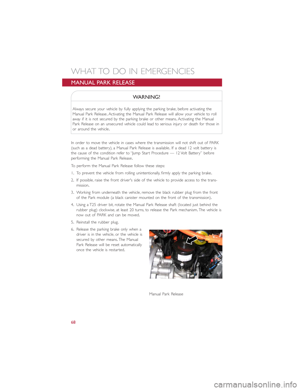
3.Working from underneath the vehicle, remove the black rubber plug from the front
of the Park module (a black canister mounted on the front of the transmission).
4.Using a T25 driver bit, rotate the Manual Park Release shaft (located just behind the
rubber plug) clockwise, at least 20 turns, to release the Park mechanism.The vehicle is
now out of PARK and can be moved.
5.Reinstall the rubber plug.
6.Release the parking brake only when a
driver is in the vehicle, or the vehicle is
secured by other means.The Manual
Park Release will be reset automatically
once the vehicle is restarted.
Manual Park Release
WHAT TO DO IN EMERGENCIES
68