warning FIAT 500E 2014 2.G Owner's Manual
[x] Cancel search | Manufacturer: FIAT, Model Year: 2014, Model line: 500E, Model: FIAT 500E 2014 2.GPages: 92, PDF Size: 3.24 MB
Page 54 of 92
PROGRAMMABLE FEATURES
Electronic Vehicle Information Center (EVIC)
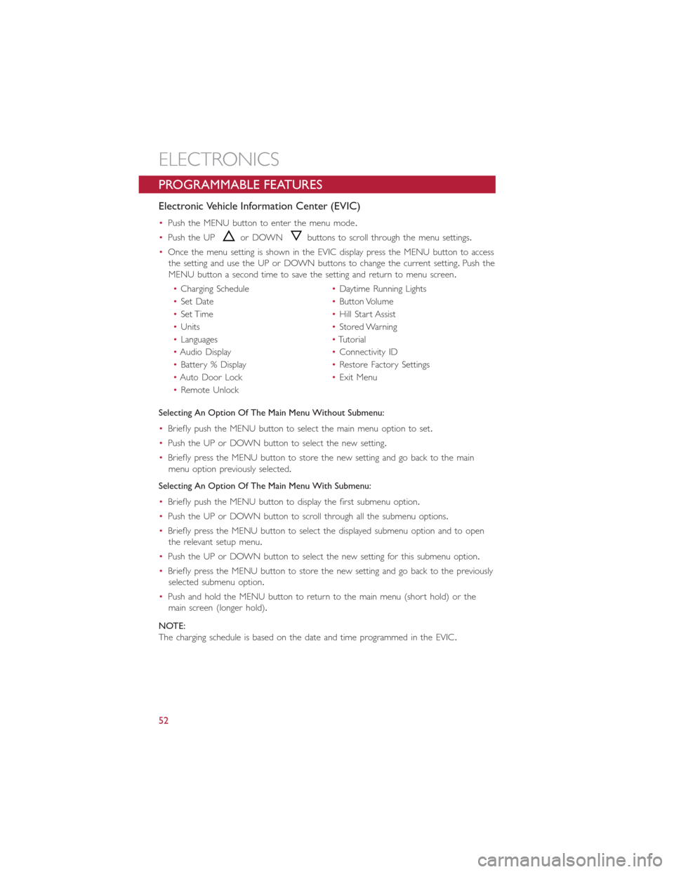
•Push the MENU button to enter the menu mode.
•Push the UP
or DOWNbuttons to scroll through the menu settings.
•Once the menu setting is shown in the EVIC display press the MENU button to access
the setting and use the UP or DOWN buttons to change the current setting.Push the
MENU button a second time to save the setting and return to menu screen.
•Charging Schedule•Daytime Running Lights
•Set Date•Button Volume
•Set Time•Hill Start Assist
•Units•Stored Warning
•Languages•Tutorial
•Audio Display•Connectivity ID
•Battery % Display•Restore Factory Settings
•Auto Door Lock•Exit Menu
•Remote Unlock
Selecting An Option Of The Main Menu Without Submenu:
•Briefly push the MENU button to select the main menu option to set.
•Push the UP or DOWN button to select the new setting.
•Briefly press the MENU button to store the new setting and go back to the main
menu option previously selected.
Selecting An Option Of The Main Menu With Submenu:
•Briefly push the MENU button to display the first submenu option.
•Push the UP or DOWN button to scroll through all the submenu options.
•Briefly press the MENU button to select the displayed submenu option and to open
the relevant setup menu.
•Push the UP or DOWN button to select the new setting for this submenu option.
•Briefly press the MENU button to store the new setting and go back to the previously
selected submenu option.
•Push and hold the MENU button to return to the main menu (short hold) or the
main screen (longer hold).
NOTE:
The charging schedule is based on the date and time programmed in the EVIC.
ELECTRONICS
52
Page 58 of 92
24-HOUR ROADSIDE ASSISTANCE
•If your FIAT 500e requires jump start assistance, tire service, lockout service or towing
due to a defect covered under the Basic Limited Warranty, dial toll-free
1-888-242-6342.See your Warranty booklet for further details.
•Provide your name, vehicle identification number and license plate number.
•Provide your location, including telephone number, from which you are calling.
•Briefly describe the nature of the problem and answer a few simple questions.
•You will be given the name of the service provider and an estimated time of arrival.If
you feel you are in an “unsafe situation”, please let us know.With your consent, we will
contact local police or safety authorities.
INSTRUMENT CLUSTER WARNING LIGHTS
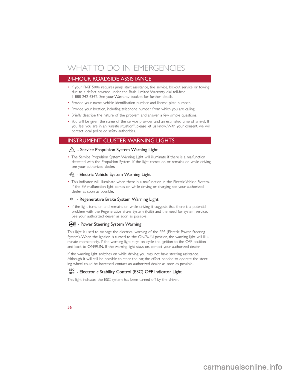
- Service Propulsion System Warning Light
•The Service Propulsion System Warning Light will illuminate if there is a malfunction
detected with the Propulsion System.If the light comes on or remains on while driving
see your authorized dealer.
- Electric Vehicle System Warning Light
•This indicator will illuminate when there is a malfunction in the Electric Vehicle System.
If the EV malfunction light comes on while driving or charging see your authorized
dealer as soon as possible.
- Regenerative Brake System Warning Light
•If the light turns on and remains on while driving, it suggests that there is a potential
problem with the Regenerative Brake System (RBS) and the need for system service.
See your authorized dealer as soon as possible.
- Power Steering System Warning
This light is used to manage the electrical warning of the EPS (Electric Power Steering
System).When the ignition is turned to the ON/RUN position, the warning light will illu-
minate momentarily.If the warning light stays on, cycle the ignition to the OFF position
and back to ON/RUN.If the warning light stays on, contact your authorized dealer.
If the warning light switches on while driving you may not have steering assistance.
Although it will still be possible to steer the car, the effort needed to operate the steer-
ing wheel could be increased: contact an authorized dealer as soon as possible.
- Electronic Stability Control (ESC) OFF Indicator Light
This light indicates the ESC system has been turned off by the driver.
WHAT TO DO IN EMERGENCIES
56
Page 60 of 92
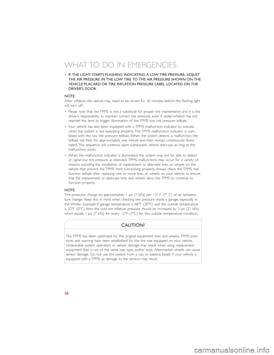
•IF THE LIGHT STARTS FLASHING INDICATING A LOW TIRE PRESSURE, ADJUST
THE AIR PRESSURE IN THE LOW TIRE TO THE AIR PRESSURE SHOWN ON THE
VEHICLE PLACARD OR TIRE INFLATION PRESSURE LABEL LOCATED ON THE
DRIVER'S DOOR.
NOTE:
After inflation, the vehicle may need to be driven for 20 minutes before the flashing light
will turn off.
•Please note that the TPMS is not a substitute for proper tire maintenance, and it is the
driver’s responsibility to maintain correct tire pressure, even if under-inflation has not
reached the level to trigger illumination of the TPMS low tire pressure telltale.
•Your vehicle has also been equipped with a TPMS malfunction indicator to indicate
when the system is not operating properly.The TPMS malfunction indicator is com-
bined with the low tire pressure telltale.When the system detects a malfunction, the
telltale will flash for approximately one minute and then remain continuously illumi-
nated.This sequence will continue upon subsequent vehicle start-ups as long as the
malfunction exists.
•When the malfunction indicator is illuminated, the system may not be able to detect
or signal low tire pressure as intended.TPMS malfunctions may occur for a variety of
reasons, including the installation of replacement or alternate tires or wheels on the
vehicle that prevent the TPMS from functioning properly.Always check the TPMS mal-
function telltale after replacing one or more tires or wheels on your vehicle, to ensure
that the replacement or alternate tires and wheels allow the TPMS to continue to
function properly.
NOTE:
Tire pressures change by approximately 1 psi (7 kPa) per 12° F (7° C) of air tempera-
ture change.Keep this in mind when checking tire pressure inside a garage, especially in
the Winter.Example: If garage temperature is 68°F (20°C) and the outside temperature
is 32°F (0°C), then the cold tire inflation pressure should be increased by 3 psi (21 kPa),
which equals 1 psi (7 kPa) for every 12°F (7°C) for this outside temperature condition.
CAUTION!
The TPMS has been optimized for the original equipment tires and wheels.TPMS pres-
sures and warning have been established for the tire size equipped on your vehicle.
Undesirable system operation or sensor damage may result when using replacement
equipment that is not of the same size, type, and/or style.Aftermarket wheels can cause
sensor damage.Do not use tire sealant from a can, or balance beads if your vehicle is
equipped with a TPMS, as damage to the sensors may result.
WHAT TO DO IN EMERGENCIES
58
Page 61 of 92
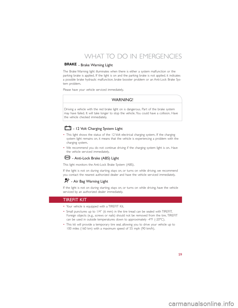
BRAKE- Brake Warning Light
The Brake Warning light illuminates when there is either a system malfunction or the
parking brake is applied.If the light is on and the parking brake is not applied, it indicates
a possible brake hydraulic malfunction, brake booster problem or an Anti-Lock Brake Sys-
tem problem.
Please have your vehicle serviced immediately.
WARNING!
Driving a vehicle with the red brake light on is dangerous.Part of the brake system
may have failed.It will take longer to stop the vehicle.You could have a collision.Have
the vehicle checked immediately.
- 12 Volt Charging System Light
•This light shows the status of the 12 Volt electrical charging system.If the charging
system light remains on, it means that the vehicle is experiencing a problem with the
charging system.
•We recommend you do not continue driving if the charging system light is on.Have
the vehicle serviced immediately.
- Anti-Lock Brake (ABS) Light
This light monitors the Anti-Lock Brake System (ABS).
If the light is not on during starting, stays on, or turns on while driving, we recommend
you contact the nearest authorized dealer and have the vehicle serviced immediately.
- Air Bag Warning Light
If the light is not on during starting, stays on, or turns on while driving, have the vehicle
serviced by an authorized dealer immediately.
TIREFIT KIT
•Your vehicle is equipped with a TIREFIT Kit.
•Small punctures up to 1/4” (6 mm) in the tire tread can be sealed with TIREFIT.
Foreign objects (e.g., screws or nails) should not be removed from the tire.TIREFIT
can be used in outside temperatures down to approximately -4°F (-20°C).
•This kit will provide a temporary tire seal, allowing you to drive your vehicle up to
100 miles (160 km) with a maximum speed of 55 mph (90 km/h).
WHAT TO DO IN EMERGENCIES
59
Page 63 of 92
TIREFIT Usage Precautions
•Replace the TIREFIT Sealant Bottle (1) and Sealant Hose (6) prior to the expiration
date (printed on the bottle label) to assure optimum operation of the system.Refer to
“Sealing a Tire with TIREFIT” section (F) “Sealant Bottle and Hose Replacement.”
•The Sealant Bottle (1) and Sealant Hose (6) are a one tire application use.After each
use, always replace these components immediately at an authorized dealer.
•When the TIREFIT sealant is in a liquid form, clean water, and a damp cloth will re-
move the material from the vehicle or tire and wheel components.Once the sealant
dries, it can easily be peeled off and properly discarded.
•For optimum performance, make sure the valve stem on the wheel is free of debris
before connecting the TIREFIT kit.
•
You can use the TIREFIT air pump to inflate bicycle tires.The kit also comes with two
needles, located in the Accessory Storage Compartment (on the bottom of the air pump)
for inflating sport balls, rafts, or similar inflatable items.However, use only the Air Pump
Hose (7) and make sure the Mode Select Knob (5) is in the Air Mode when inflating such
items to avoid injecting sealant into them.The TIREFIT Sealant is only intended to seal punc-
tures less than 1/4” (6 mm) diameter in the tread of your vehicle.
•Do not lift or carry the TIREFIT kit by the hoses.
Sealing A Tire With TIREFIT
(A) Whenever You Stop To Use TIREFIT:
1.Pull over to a safe location and turn on the vehicle’s Hazard Warning flashers.
2.Verify that the valve stem (on the wheel with the deflated tire) is in a position that is
near to the ground.This will allow the TIREFIT Hoses (6) and (7) to reach the valve
stem and keep the TIREFIT kit flat on the ground.This will provide the best position-
ing of the kit when injecting the sealant into the deflated tire and running the air
pump.Move the vehicle as necessary to place the valve stem in this position before
proceeding.
3.Place the transmission in PARK (auto transmission) or in Gear (manual transmission)
and cycle the ignition to the OFF position.
4.Set the parking brake.
(B) Setting Up To Use TIREFIT:
1.Turn the Mode Select Knob (5) to the Sealant Mode position.
2.Uncoil the Sealant Hose (6) and then remove the cap from the fitting at the end of
the hose.
3.Place the TIREFIT kit flat on the ground next to the deflated tire.
4.Remove the cap from the valve stem and then screw the fitting at the end of the
Sealant Hose (6) onto the valve stem.
5.Uncoil the Power Plug (8) and insert the plug into the vehicle’s 12 Volt power outlet.
6.Do not remove foreign objects (e.g., screws or nails) from the tire.
WHAT TO DO IN EMERGENCIES
61
Page 67 of 92
WARNING!
•Do not attempt to seal a tire on the side of the vehicle closest to traffic.Pull far
enough off the road to avoid the danger of being hit when using the TIREFIT kit.
•Do not use TIREFIT or drive the vehicle under the following circumstances:
•If the puncture in the tire tread is approximately 1/4”.(6 mm) or larger.
•If the tire has any sidewall damage.
•If the tire has any damage from driving with extremely low tire pressure.
•If the tire has any damage from driving on a flat tire.
•If the wheel has any damage.
•If you are unsure of the condition of the tire or the wheel.
•Keep TIREFIT away from open flames or heat source.
•A loose TIREFIT kit thrown forward in a collision or hard stop could endanger the
occupants of the vehicle.Always stow the TIREFIT kit in the place provided.Failure
to follow these warnings can result in injuries that are serious or fatal to you, your
passengers, and others around you.
•Take care not to allow the contents of TIREFIT to come in contact with hair, eyes,
or clothing.TIREFIT is harmful if inhaled, swallowed, or absorbed through the skin.
It causes skin, eye, and respiratory irritation.Flush immediately with plenty of water
if there is any contact with eyes or skin.Change clothing as soon as possible, if
there is any contact with clothing.
•TIREFIT Sealant solution contains latex.In case of an allergic reaction or rash, con-
sult a physician immediately.Keep TIREFIT out of reach of children.If swallowed,
rinse mouth immediately with plenty of water and drink plenty of water.Do not
induce vomiting! Consult a physician immediately.
•TIREFIT is not a permanent flat tire repair.Have the tire inspected and repaired
or replaced after using TIREFIT.Do not exceed 55 mph (88 km/h) until the tire is
repaired or replaced.Failure to follow this warning can result in injuries that are
serious or fatal to you, your passengers, and others around you.
JUMP-STARTING PROCEDURE — 12 VOLT BATTERY
•If your vehicle has a discharged 12 Volt battery, it can be jump-started using a set of
jumper cables and a battery in another vehicle or by using a portable battery booster
pack.Jump-starting can be dangerous if done improperly so please follow the proce-
dures in this section carefully.
NOTE:
When using a portable battery booster pack, follow the manufacturer’s operating instruc-
tions and precautions.
WHAT TO DO IN EMERGENCIES
65
Page 69 of 92
CAUTION!
•Accessories that can be plugged into the vehicle power outlets draw power from
the vehicle’s battery, even when not in use (i.e., cellular phones, etc.).Eventually, if
plugged in long enough, the vehicle’s battery will discharge sufficiently to degrade
battery life and/or prevent the engine from starting.
•Do not use a portable battery booster pack or any other booster source with a
system voltage greater than 12 Volts or damage to the battery, starter motor, alter-
nator or electrical system may occur.
•Failure to follow these procedures could result in damage to the charging system
of the booster vehicle or the discharged vehicle.
WARNING!
•Do not attempt jump-starting if the battery is frozen.It could rupture or explode
and cause personal injury.
•Take care to avoid the radiator cooling fan whenever the hood is raised.It can
start anytime the ignition switch is on.You can be injured by moving fan blades.
•Remove any metal jewelry such as watch bands or bracelets that might make an
inadvertent electrical contact.You could be seriously injured.
•Batteries contain sulfuric acid that can burn your skin or eyes and generate hydro-
gen gas which is flammable and explosive.Keep open flames or sparks away from
the battery.
•Do not allow vehicles to touch each other as this could establish a ground con-
nection and personal injury could result.
•Failure to follow this procedure could result in personal injury or property damage
due to battery explosion.
•
Do not connect the cable to the negative post (-)
of the discharged battery.The resulting electrical spark could cause the battery to
explode and could result in personal injury.
WHAT TO DO IN EMERGENCIES
67
Page 70 of 92
MANUAL PARK RELEASE
WARNING!
Always secure your vehicle by fully applying the parking brake, before activating the
Manual Park Release.Activating the Manual Park Release will allow your vehicle to roll
away if it is not secured by the parking brake or other means.Activating the Manual
Park Release on an unsecured vehicle could lead to serious injury or death for those in
or around the vehicle.
In order to move the vehicle in cases where the transmission will not shift out of PARK
(such as a dead battery), a Manual Park Release is available.Ifadead12voltbatteryis
the cause of the condition refer to “Jump Start Procedure — 12 Volt Battery” before
performing the Manual Park Release.
To perform the Manual Park Release follow these steps:
1.To prevent the vehicle from rolling unintentionally, firmly apply the parking brake.
2.If possible, raise the front driver's side of the vehicle to provide access to the trans-
mission.
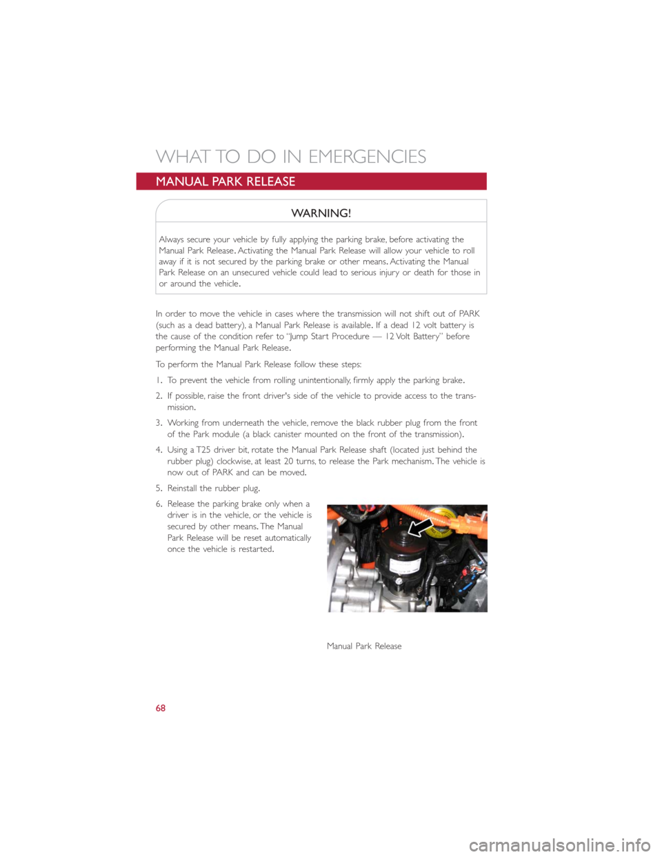
3.Working from underneath the vehicle, remove the black rubber plug from the front
of the Park module (a black canister mounted on the front of the transmission).
4.Using a T25 driver bit, rotate the Manual Park Release shaft (located just behind the
rubber plug) clockwise, at least 20 turns, to release the Park mechanism.The vehicle is
now out of PARK and can be moved.
5.Reinstall the rubber plug.
6.Release the parking brake only when a
driver is in the vehicle, or the vehicle is
secured by other means.The Manual
Park Release will be reset automatically
once the vehicle is restarted.
Manual Park Release
WHAT TO DO IN EMERGENCIES
68
Page 73 of 92
WARNING!
Fast spinning tires can be dangerous.Forces generated by excessive wheel speeds may
cause damage, or even failure, of the axle and tires.A tire could explode and injure
someone.Do not spin your vehicle's wheels faster than 30 mph (48 km/h) or for lon-
ger than 30 seconds continuously without stopping when you are stuck and do not let
anyone near a spinning wheel, no matter what the speed.
EVENT DATA RECORDER (EDR)
This vehicle is equipped with an Event Data Recorder (EDR).The main purpose of an
EDR is to record, in certain crash or near crash-like situations, such as an air bag deploy-
ment or hitting a road obstacle, data that will assist in understanding how a vehicle’s sys-
tems performed.The EDR is designed to record data related to vehicle dynamics and
safety systems for a short period of time, typically 30 seconds or less.The EDR in this
vehicle is designed to record such data as:
•How various systems in your vehicle were operating.
•Whether or not the driver and passenger safety belts were buckled/fastened.
•How far (if at all) the driver was depressing the accelerator and/or brake pedal.
•How fast the vehicle was traveling.
These data can help provide a better understanding of the circumstances in which
crashes and injuries occur.
NOTE:
EDR data is recorded by your vehicle only if a non-trivial crash situation occurs; no data
is recorded by the EDR under normal driving conditions and no personal data (e.g.
name, gender, age, and crash location) is recorded.However, other parties, such as law
enforcement, could combine the EDR data with the type of personally identifying data
routinely acquired during a crash investigation.
To read data recorded by an EDR, special equipment is required, and access to the ve-
hicle or the EDR is needed.In addition to the vehicle manufacturer, other parties such as
law enforcement, that have the special equipment, can read the information if they have
access to the vehicle or the EDR.
WHAT TO DO IN EMERGENCIES
71
Page 74 of 92
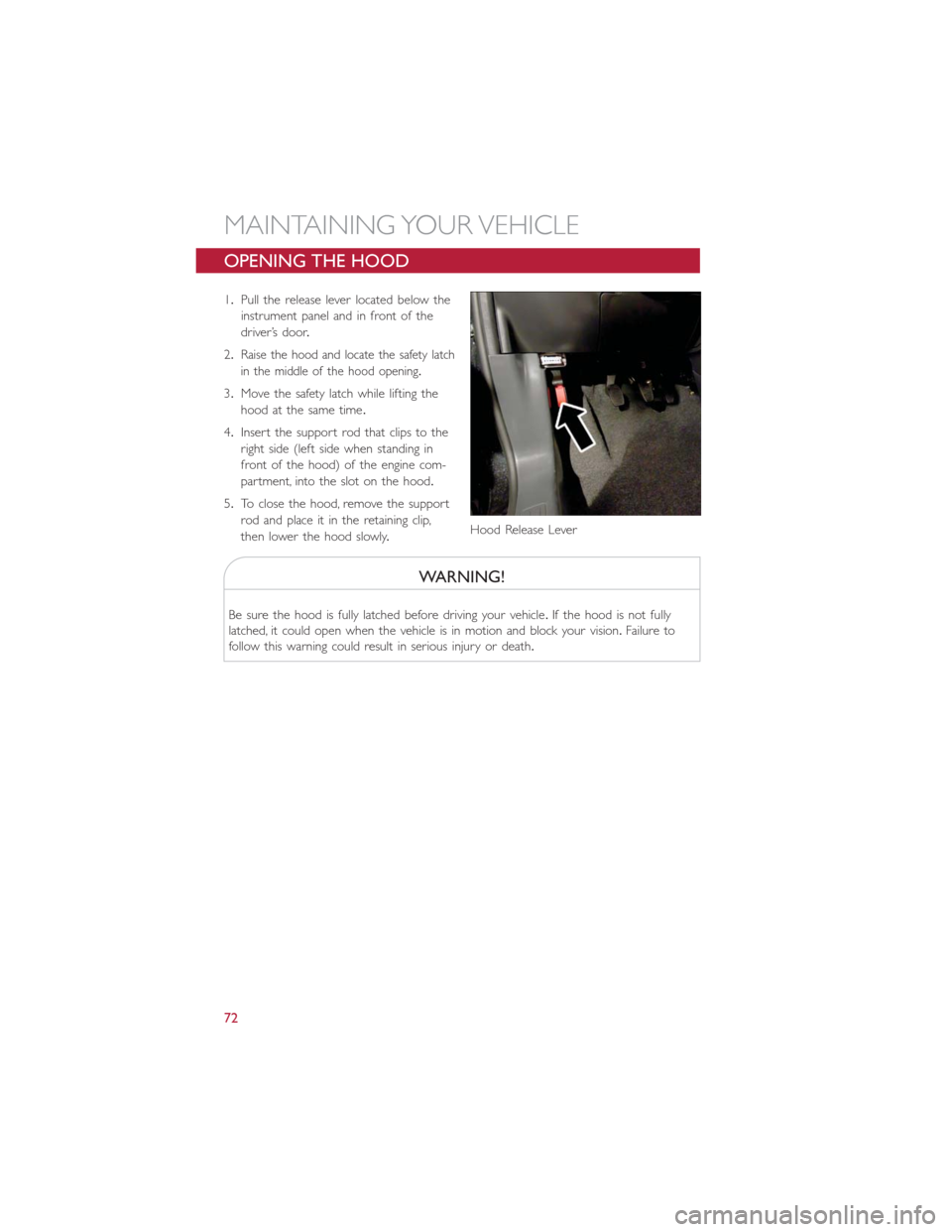
OPENING THE HOOD
1.Pull the release lever located below the
instrument panel and in front of the
driver’s door.
2.
Raise the hood and locate the safety latch
in the middle of the hood opening.
3.Move the safety latch while lifting the
hood at the same time.
4.Insert the support rod that clips to the
right side (left side when standing in
front of the hood) of the engine com-
partment, into the slot on the hood.
5.To close the hood, remove the support
rod and place it in the retaining clip,
then lower the hood slowly.
WARNING!
Be sure the hood is fully latched before driving your vehicle.If the hood is not fully
latched, it could open when the vehicle is in motion and block your vision.Failure to
follow this warning could result in serious injury or death.
Hood Release Lever
MAINTAINING YOUR VEHICLE
72