FIAT 500E 2015 2.G Owners Manual
Manufacturer: FIAT, Model Year: 2015, Model line: 500E, Model: FIAT 500E 2015 2.GPages: 367, PDF Size: 9.42 MB
Page 271 of 367
Once you repair or replace the original road tire and
reinstall it, the TPMS will update automatically. In addi-
tion, the “Tire Pressure Monitoring Telltale Light” will
turn off and the graphic in the EVIC will display a new
pressure value instead of dashes (- -), as long as no tire
pressure is below the low-pressure warning limit in any
of the four active road tires. The vehicle may need to be
driven for up to 20 minutes above 15 mph (24 km/h) in
order for the TPMS to receive this information.
General Information
This device complies with Part 15 of the FCC rules and
RSS 210 of Industry Canada. Operation is subject to the
following conditions:
•This device may not cause harmful interference.
•This device must accept any interference received, includ-
ing interference that may cause undesired operation. The
tire pressure sensors are covered under one of the follow-
ing licenses: United States MRXC4W4MA4 Canada
2546A-C4W4MA4.
TRAILER TOWING
Trailer towing with this vehicle is not recommended.
5
STARTING AND OPERATING 269
Page 272 of 367
RECREATIONAL TOWING (BEHIND MOTORHOME, ETC.)
Towing This Vehicle Behind Another Vehicle
Towing ConditionWheels OFF the GroundSingle-Speed Transmission
Flat TowNONENOT ALLOWED
Dolly TowFrontOK
RearNOT ALLOWED
On TrailerALLOK
NOTE:This vehicle must be towed on a dolly or vehicle
trailer with the front wheelsOFFthe ground.
CAUTION!
Towing this vehicle in violation of the above require-
ments can cause severe transmission damage. Dam-
age from improper towing is not covered under the
New Vehicle Limited Warranty.
EXTENDING YOUR DRIVING RANGE PER
CHARGE
The drive system and cabin temperature management
features use the most energy from the high voltage
battery. Reducing energy draw from these features are
the easiest and most effective way to extend driving
range.
270 STARTING AND OPERATING
Page 273 of 367
The 500e uses high voltage components to heat and cool
the cabin, so when using automatic climate control,
consider setting temperatures a few degrees higher or
lower during hot and cold days. If your 500e has been
soaking in hot or cold temperatures for an extended
period, it is recommended that the car be preconditioned
using the FIAT Access smartphone app while still
plugged into a charging source. This will allow 500e to
use external power to establish a comfortable cabin
temperature before the drive and allow the battery to
maintain the temperature at significantly lower energy
levels.
Additional tips:
•Keep tires properly inflated
•When practical, choose surface streets over the high-
way, and work to maintain a steady speed
•Avoid carrying nonessential cargo
•Be mindful of adding external accessories that may
increase aerodynamic drag
•Perform all scheduled maintenance at recommended
intervals
Driver Behavior Gauge
To help the driver extend the driving range of the high
voltage battery your vehicle is equipped with a Driver
Behavior Gauge. The Driver Behavior Gauge is located
on the right side of the instrument cluster and contains
three driving ranges:
•Power
The needle will move into the Power range when under
acceleration.
•ECO
The needle will move into the ECO range when you are
maximizing the driving range of the high voltage battery.
5
STARTING AND OPERATING 271
Page 274 of 367
•Charge
The needle will move into the Charge range when battery
regeneration is active (either coasting or braking).
Range Projection
This area of the cluster is used to display the projected
range considering current battery charge and previous
energy use. The two arrows to the left of the mileage are
used to forecast the effect of recent driving.
•When both arrows are grey, expect the range to drop
approximately one mile for each mile driven.
•When the up arrow is highlighted, expect the range
number to hold steady or increase while driving.
•When the down arrow is highlighted, expect the range
number to decrease more than one mile for each mile
driven.
Driver Behavior Gauge
272 STARTING AND OPERATING
Page 275 of 367
WHAT TO DO IN EMERGENCIES
CONTENTS
!HAZARD WARNING FLASHERS...........274
!WHEEL AND TIRE TORQUE
SPECIFICATIONS......................275
▫Torque Specifications...................275
!TIRE SERVICE KIT — IF EQUIPPED.........276
▫Tire Service Kit Storage.................277
▫Tire Service Kit Components And Operation . .277
▫Tire Service Kit Usage Precautions..........278
▫Sealing A Tire With Tire Service Kit.........281
!JUMP-STARTING PROCEDURE (12 VOLT
BATTERY ONLY).......................287
▫Preparations For Jump-Start..............287
▫Jump-Starting Procedure................289
!FREEING A STUCK VEHICLE.............291
!MANUAL PARK RELEASE................292
!TOWING A DISABLED VEHICLE...........293
6
Page 276 of 367
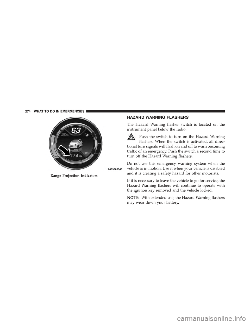
HAZARD WARNING FLASHERS
The Hazard Warning flasher switch is located on the
instrument panel below the radio.
Push the switch to turn on the Hazard Warning
flashers. When the switch is activated, all direc-
tional turn signals will flash on and off to warn oncoming
traffic of an emergency. Push the switch a second time to
turn off the Hazard Warning flashers.
Do not use this emergency warning system when the
vehicle is in motion. Use it when your vehicle is disabled
and it is creating a safety hazard for other motorists.
If it is necessary to leave the vehicle to go for service, the
Hazard Warning flashers will continue to operate with
the ignition key removed and the vehicle locked.
NOTE:With extended use, the Hazard Warning flashers
may wear down your battery.
Range Projection Indicators
274 WHAT TO DO IN EMERGENCIES
Page 277 of 367
WHEEL AND TIRE TORQUE SPECIFICATIONS
Proper lug nut/bolt torque is very important to ensure
that the wheel is properly mounted to the vehicle. Any
time a wheel has been removed and reinstalled on the
vehicle the lug nuts/bolts should be torqued using a
properly calibrated torque wrench.
Torque Specifications
Lug Nut/Bolt Torque **Lug Nut/
Bolt Size
Lug Nut/
Bolt Socket
Size
66 Ft-Lbs (90 N·m)
Steel Wheels Only
75 Ft-Lbs (100 N·m)
Aluminum Wheels
Only
M12 x 1.25 17 mm
**Use only Chrysler recommended lug nuts/bolts and
clean or remove any dirt or oil before tightening.
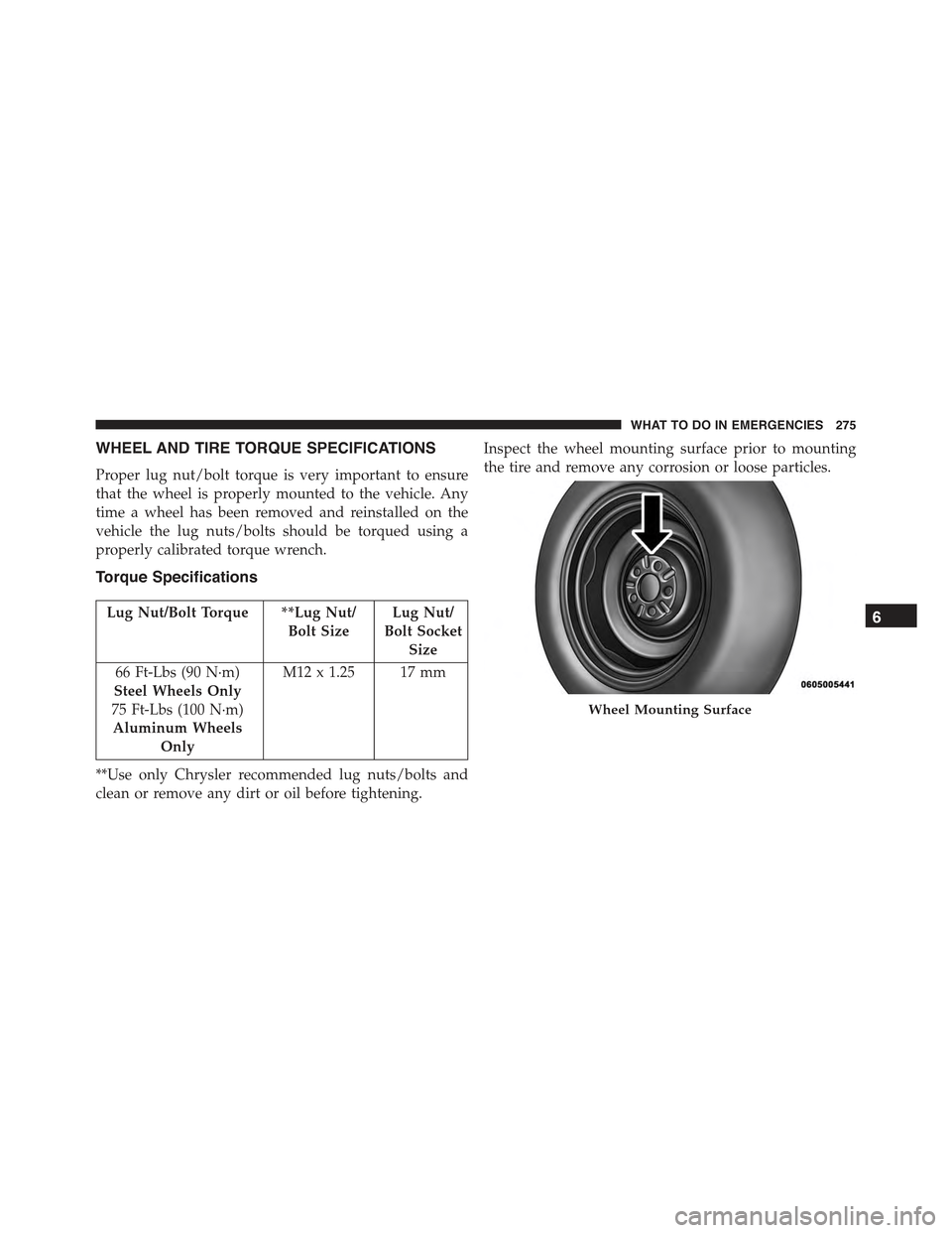
Inspect the wheel mounting surface prior to mounting
the tire and remove any corrosion or loose particles.
Wheel Mounting Surface
6
WHAT TO DO IN EMERGENCIES 275
Page 278 of 367
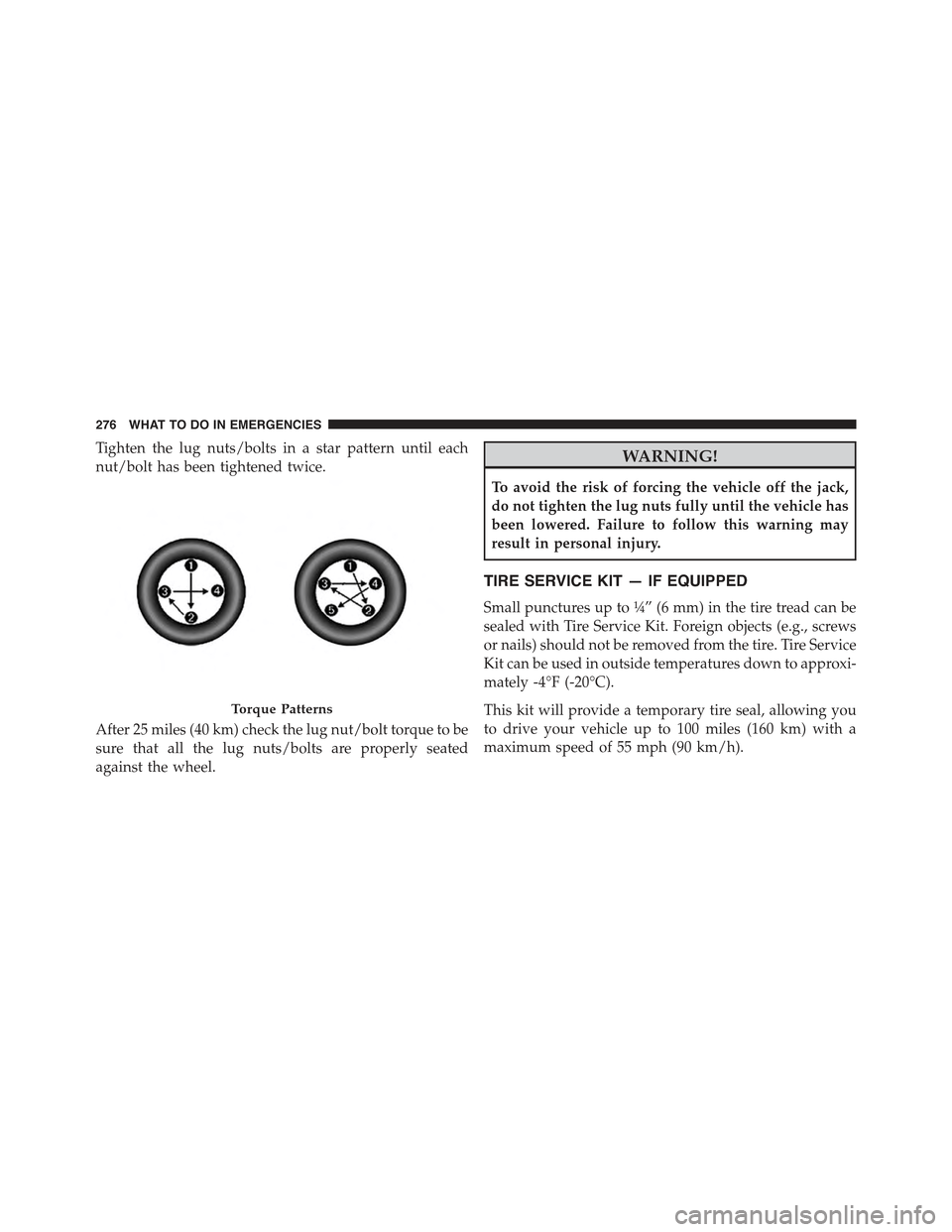
Tighten the lug nuts/bolts in a star pattern until each
nut/bolt has been tightened twice.
After 25 miles (40 km) check the lug nut/bolt torque to be
sure that all the lug nuts/bolts are properly seated
against the wheel.
WARNING!
To avoid the risk of forcing the vehicle off the jack,
do not tighten the lug nuts fully until the vehicle has
been lowered. Failure to follow this warning may
result in personal injury.
TIRE SERVICE KIT — IF EQUIPPED
Small punctures up to¼” (6 mm) in the tire tread can be
sealed with Tire Service Kit. Foreign objects (e.g., screws
or nails) should not be removed from the tire. Tire Service
Kit can be used in outside temperatures down to approxi-
mately -4°F (-20°C).
This kit will provide a temporary tire seal, allowing you
to drive your vehicle up to 100 miles (160 km) with a
maximum speed of 55 mph (90 km/h).
Torque Patterns
276 WHAT TO DO IN EMERGENCIES
Page 279 of 367
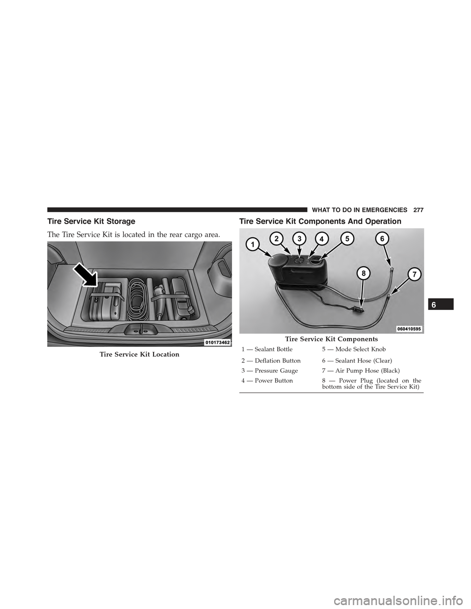
Tire Service Kit Storage
The Tire Service Kit is located in the rear cargo area.
Tire Service Kit Components And Operation
Tire Service Kit Location
Tire Service Kit Components
1 — Sealant Bottle 5 — Mode Select Knob
2 — Deflation Button 6 — Sealant Hose (Clear)
3—PressureGauge 7—AirPumpHose(Black)
4 — Power Button 8 — Power Plug (located on thebottom side of the Tire Service Kit)
6
WHAT TO DO IN EMERGENCIES 277
Page 280 of 367
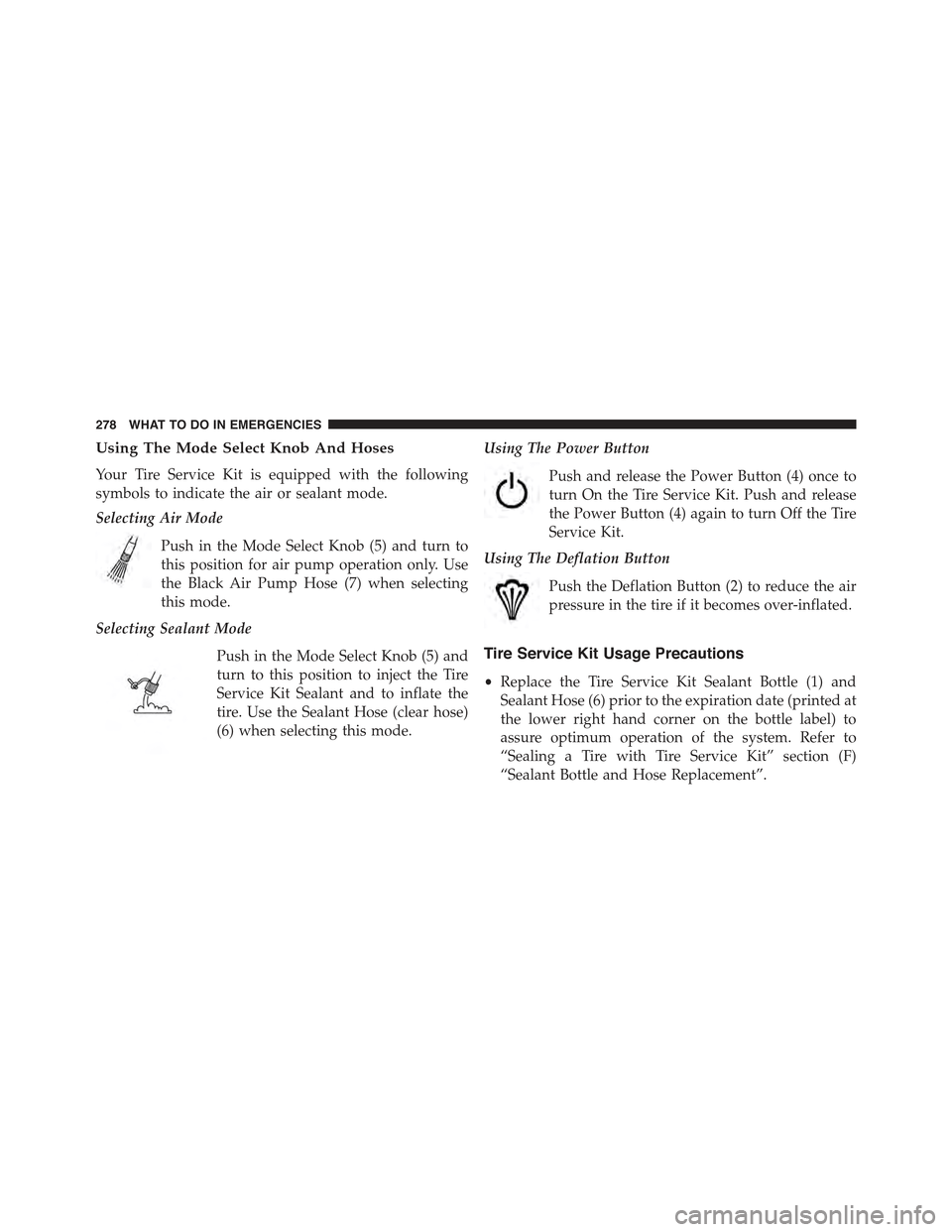
Using The Mode Select Knob And Hoses
Your Tire Service Kit is equipped with the following
symbols to indicate the air or sealant mode.
Selecting Air Mode
Push in the Mode Select Knob (5) and turn to
this position for air pump operation only. Use
the Black Air Pump Hose (7) when selecting
this mode.
Selecting Sealant Mode
Push in the Mode Select Knob (5) and
turn to this position to inject the Tire
Service Kit Sealant and to inflate the
tire. Use the Sealant Hose (clear hose)
(6) when selecting this mode.
Using The Power Button
Push and release the Power Button (4) once to
turn On the Tire Service Kit. Push and release
the Power Button (4) again to turn Off the Tire
Service Kit.
Using The Deflation Button
Push the Deflation Button (2) to reduce the air
pressure in the tire if it becomes over-inflated.
Tire Service Kit Usage Precautions
•Replace the Tire Service Kit Sealant Bottle (1) and
Sealant Hose (6) prior to the expiration date (printed at
the lower right hand corner on the bottle label) to
assure optimum operation of the system. Refer to
“Sealing a Tire with Tire Service Kit” section (F)
“Sealant Bottle and Hose Replacement”.
278 WHAT TO DO IN EMERGENCIES