replace FIAT 500E 2015 2.G Owner's Guide
[x] Cancel search | Manufacturer: FIAT, Model Year: 2015, Model line: 500E, Model: FIAT 500E 2015 2.GPages: 367, PDF Size: 9.42 MB
Page 287 of 367
(E) After Driving:
Pull over to a safe location. Refer to “Whenever You Stop
to Use Tire Service Kit” before continuing.
1. Push in the Mode Select Knob (5) and turn to the Air
Mode position.
2. Uncoil the power plug and insert the plug into the
vehicle’s 12 Volt power outlet.
3. Uncoil the Air Pump Hose (7) (black in color) and
screw the fitting at the end of hose (7) onto the valve
stem.
4. Check the pressure in the tire by reading the Pressure
Gauge (3).
If tire pressure is less than 19 psi (1.3 Bar):
The tire is too badly damaged. Do not attempt to drive
the vehicle further. Call for assistance.
If the tire pressure is 19 psi (1.3 Bar) or higher:
1. Push the Power Button (4) to turn on Tire Service Kit
and inflate the tire to the pressure indicated on the tire
and loading information label on the driver-side door
opening.
NOTE:If the tire becomes over-inflated, push the Defla-
tion Button to reduce the tire pressure to the recom-
mended inflation pressure before continuing.
2. Disconnect the Tire Service Kit from the valve stem,
reinstall the cap on the valve stem and unplug from
12 Volt outlet.
3. Place the Tire Service Kit in its proper storage area in
the vehicle.
4. Have the tire inspected and repaired or replaced at the
earliest opportunity at an authorized dealer or tire
service center.
6
WHAT TO DO IN EMERGENCIES 285
Page 288 of 367
5. Remove the Speed Limit sticker from the instrument
panel after the tire has been repaired.
6. Replace the Sealant Bottle (1) and Sealant Hose (6)
assembly at your authorized dealer as soon as pos-
sible. Refer to (F) “Sealant Bottle and Hose Replace-
ment”.
NOTE:When having the tire serviced, advise the autho-
rized dealer or service center that the tire has been sealed
using the Tire Service Kit.
(F) Sealant Bottle And Hose Replacement:
1. Uncoil the Sealant Hose (6) (clear in color).
2. Locate the round Sealant Bottle release button in the
recessed area under the sealant bottle.
3. Push the Sealant Bottle release button. The Sealant
Bottle (1) will pop up. Remove the bottle and dispose
of it accordingly.
4. Clean any remaining sealant from the Tire Service Kit
housing.
5. Position the new Sealant Bottle (1) in the housing so
that the Sealant Hose (6) aligns with the hose slot in
the front of the housing. Push the bottle into the
housing. An audible click will be heard indicating the
bottle is locked into place.
6. Verify that the cap is installed on the fitting at the end
of the Sealant Hose (6) and return the hose to its
storage area (located on the bottom of the air pump).
7. Return the Tire Service Kit to its storage location in the
vehicle.
286 WHAT TO DO IN EMERGENCIES
Page 297 of 367
MAINTAINING YOUR VEHICLE
CONTENTS
!UNDERHOOD COMPARTMENT...........297
!REPLACEMENT PARTS..................298
!DEALER SERVICE......................298
!MAINTENANCE PROCEDURES...........299
▫Power Electronics And Battery Thermal
Management Systems...................300
▫Power Electronics and Battery Thermal
Management Systems — Coolant Level
Check..............................300
▫Power Electronics and Battery Thermal
Management Systems — Cooling Pressure
Caps...............................302
▫Selection Of Coolant...................303
▫Adding Coolant.......................304
▫Power Electronics and Battery Thermal
Management Systems — Drain, Flush And
Refill..............................305
▫Disposal Of Used Power Electronics and Battery
Thermal Management Systems Coolant......305
7
Page 298 of 367
▫Points To Remember...................306
▫Maintenance-Free Battery 12 Volt..........306
▫Air Conditioner Maintenance.............308
▫Body Lubrication.....................309
▫Wiper Blades........................309
▫Adding Washer Fluid..................311
▫Brake System........................312
▫Appearance Care And Protection From
Corrosion...........................314
!FUSES..............................321
▫Interior Fuses........................322
▫Power Distribution Center #1.............325
▫Power Distribution Center (PDC) #2........327
!VEHICLE STORAGE.....................329
!REPLACEMENT BULBS.................329
!BULB REPLACEMENT..................330
▫Headlamps Low Beam and High Beam......330
▫Front Turn Signal, Parking And Daytime
Running Lamps.......................331
▫Front Fog Lamps......................331
▫Front/Rear Side Marker Lamps............332
▫Rear Tail, Stop, Backup And Turn Signal
Lamps.............................332
▫Center High Mounted Stop Lamp (CHMSL) . . .333
!FLUID CAPACITIES....................333
!FLUIDS, LUBES, AND GENUINE PARTS.....334
296 MAINTAINING YOUR VEHICLE
Page 300 of 367
REPLACEMENT PARTS
Use of genuine parts for normal/scheduled maintenance
and repairs is highly recommended to ensure the de-
signed performance. Damage or failures caused by the
use of parts which are not quality-equivalent to genuine
parts for maintenance and repairs will not be covered by
the manufacturer ’s warranty.
DEALER SERVICE
Your authorized dealer has the qualified service person-
nel, special tools, and equipment to perform all service
operations in an expert manner. Service Manuals are
available which include detailed service information for
your vehicle. Refer to these Service Manuals before
attempting any procedure yourself.
NOTE:Intentional tampering with emissions control
systems may void your warranty and could result in civil
penalties being assessed against you.
WARNING!
You can be badly injured working on or around a
motor vehicle. Only do service work for which you
have the knowledge and the proper equipment. If
you have any doubt about your ability to perform a
service job, take your vehicle to a competent me-
chanic.
298 MAINTAINING YOUR VEHICLE
Page 301 of 367
MAINTENANCE PROCEDURES
WARNING!
Your vehicle has both a high voltage DC and AC
system as well as a 12 Volt system. DC and AC high
voltage are both extremely dangerous and can cause
severe burns, electric shock, serious injury or even
death. In order to avoid personal injuries:
•DO NOT TOUCH THE HIGH VOLTAGE CABLES
(ORANGE COLORED) AND/OR THE CONNEC-
TORS.
•Follow all Caution and Warning labels attached to
the High Voltage components.
•Do not remove or replace any of the 500e System
components. All replacement or repairs of 500e
System components should be performed by a
factory-trained technician at an authorized dealer.
The pages that follow contain therequiredmaintenance
services determined by the engineers who designed your
vehicle.
Besides those maintenance items specified in the fixed
maintenance schedule, there are other components which
may require servicing or replacement in the future.
CAUTION!
•Failure to properly maintain your vehicle or per-
form repairs and service when necessary could
result in more costly repairs, damage to other
components or negatively impact vehicle perfor-
mance. Immediately have potential malfunctions
examined by an authorized dealer or qualified
repair center.
(Continued)
7
MAINTAINING YOUR VEHICLE 299
Page 305 of 367
NOTE:
•The pressure caps on the reservoirs are unique and
rated at 5 PSI caps.
•Use only Mopar® replacement parts.
WARNING!
•The warning words “DO NOT OPEN HOT” on the
cooling system pressure cap are a safety precaution.
Never add coolant (antifreeze) when the cooling sys-
tem is overheated. Do not loosen or remove the cap to
cool an overheated cooling system. Heat causes pres-
sure to build up in the cooling system. To prevent
scalding or injury, do not remove the pressure cap
while the system is hot or under pressure.
•Do not use a pressure cap other than the one
specified for your vehicle. Personal injury or ve-
hicle damage may result.
Selection Of Coolant
Refer to “Fluids, Lubricants, and Genuine Parts” in
“Maintaining Your Vehicle” for further information.
CAUTION!
•Mixing of coolant (antifreeze) other than specified
Organic Additive Technology (OAT) coolant (anti-
freeze), may result in cooling system damage and
may decrease corrosion protection. Organic Addi-
tive Technology (OAT) coolant is different and
should not be mixed with Hybrid Organic Additive
Technology (HOAT) coolant (antifreeze). If a non-
OAT coolant (antifreeze) is introduced into the
cooling system in an emergency, it should be re-
placed with the specified coolant (antifreeze) as
soon as possible.
(Continued)
7
MAINTAINING YOUR VEHICLE 303
Page 306 of 367
CAUTION!(Continued)
•Do not use water alone or alcohol-based coolant
(antifreeze) products. Do not use additional rust
inhibitors or antirust products, as they may not be
compatible with the radiator coolant and may plug
the radiator.
•This vehicle has not been designed for use with
propylene glycol-based coolant (antifreeze). Use of
propylene glycol-based coolant (antifreeze) is not
recommended.
Adding Coolant
Your vehicle has been built with cooling systems that allow
extended maintenance intervals. This coolant (antifreeze)
can be used up to ten years or 150,000 miles (240,000 km)
before replacement. To prevent reducing this extended
maintenance period, it is important that you use the same
coolant (antifreeze) throughout the life of your vehicle.
Please review these recommendations for using Organic
Additive Technology (OAT) coolant (antifreeze).
When adding coolant (antifreeze):
•The manufacturer recommends using MOPAR®
Antifreeze/Coolant 10 Year/150,000 Mile Formula
OAT (Organic Additive Technology).
•Mix a minimum solution of 50% OAT coolant (anti-
freeze) and distilled water. Use higher concentrations
(not to exceed 70%) if temperatures below -34ºF (-37ºC)
are anticipated.
•Use only high purity water such as distilled or deion-
ized water when mixing the water and coolant (anti-
freeze) solution. The use of lower quality water will
reduce the amount of corrosion protection in the
cooling systems.
304 MAINTAINING YOUR VEHICLE
Page 309 of 367
WARNING!
•Battery fluid is a corrosive acid solution and can
burn or even blind you. Do not allow battery fluid
to contact your eyes, skin, or clothing. Do not lean
over a battery when attaching clamps. If acid
splashes in eyes or on skin, flush the area imme-
diately with large amounts of water. Refer to
“Jump-Starting Procedures” in “What To Do In
Emergencies” for further information.
•Battery gas is flammable and explosive. Keep
flame or sparks away from the battery. Do not use
a booster battery or any other booster source with
an output greater than 12 Volts. Do not allow cable
clamps to touch each other.
•Battery posts, terminals, and related accessories
contain lead and lead compounds. Wash hands
after handling.
(Continued)
WARNING!(Continued)
•The battery in this vehicle has a vent hose that
should not be disconnected and should only be
replaced with a battery of the same type (vented).
CAUTION!
•It is essential when replacing the cables on the
battery that the positive cable is attached to the
positive post and the negative cable is attached to
the negative post. Battery posts are marked positive
(+) and negative (-) and are identified on the
battery case. Cable clamps should be tight on the
terminal posts and free of corrosion.
(Continued)
7
MAINTAINING YOUR VEHICLE 307
Page 312 of 367
Avoid using the wiper blades to remove frost or ice from
the windshield or rear window. Make sure that they are
not frozen to the glass before turning them on to avoid
damaging the blade. Keep the blade rubber out of contact
with petroleum products.
NOTE:Life expectancy of wiper blades varies depend-
ing on geographical area and frequency of use. Poor
performance of blades may be present with chattering,
marks, water lines or wet spots. If any of these conditions
are present, clean the wiper blades or replace as neces-
sary.
Rear Wiper Blade Removal/Installation
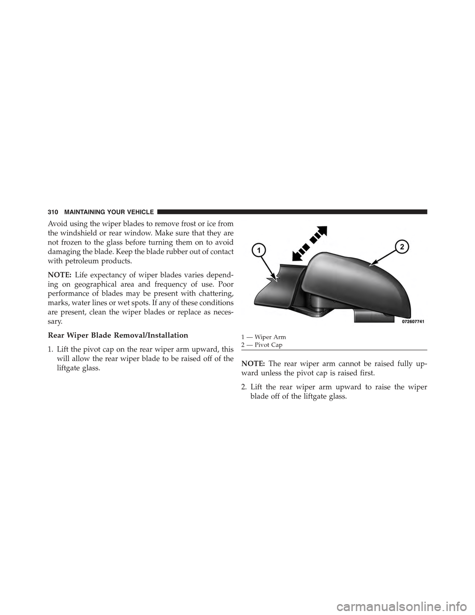
1. Lift the pivot cap on the rear wiper arm upward, this
will allow the rear wiper blade to be raised off of the
liftgate glass.NOTE:The rear wiper arm cannot be raised fully up-
ward unless the pivot cap is raised first.
2. Lift the rear wiper arm upward to raise the wiper
blade off of the liftgate glass.
1—WiperArm2 — Pivot Cap
310 MAINTAINING YOUR VEHICLE