charging FIAT 500E 2016 2.G Owner's Manual
[x] Cancel search | Manufacturer: FIAT, Model Year: 2016, Model line: 500E, Model: FIAT 500E 2016 2.GPages: 132, PDF Size: 4.59 MB
Page 41 of 132
EXTENDING YOUR DRIVING RANGE PER CHARGE
•A little knowledge will go a long way to extend your driving range on the 500e.First
and foremost understand that the drive system and cabin temperature management
features use the most energy from the high voltage battery.Reducing energy draw
from these features are the easiest and most effective way to extend driving range.
•Just like a conventional vehicle, 500e likes to keep things smooth and steady for most
efficient operation.When driving, avoid aggressive driving styles and high speeds for
extended times.When practical, choose surface streets over the highway, work to
maintain a steady speed to extend range.
•The 500e uses high voltage components to heat and cool the cabin, so a little aware-
ness can go a long way to extend range.When using automatic climate control, con-
sider setting temperatures a few degrees higher or lower during hot and cold days.If
your 500e has been soaking in hot or cold temperatures for an extended period, it is
recommended that the car be preconditioned via the Uconnect Access smartphone
app while still plugged into a charging source.This will allow 500e to use external
power to establish a comfortable cabin temperature before the drive, and allow the
battery to maintain the temperature using significantly less energy during the drive.
Additional Tips:
•Keep tires properly inflated
•Avoid carrying nonessential cargo
•Be mindful of adding external accessories that may increase aerodynamic drag
•Perform all scheduled maintenance at recommended intervals
Driving Behavior Gauge
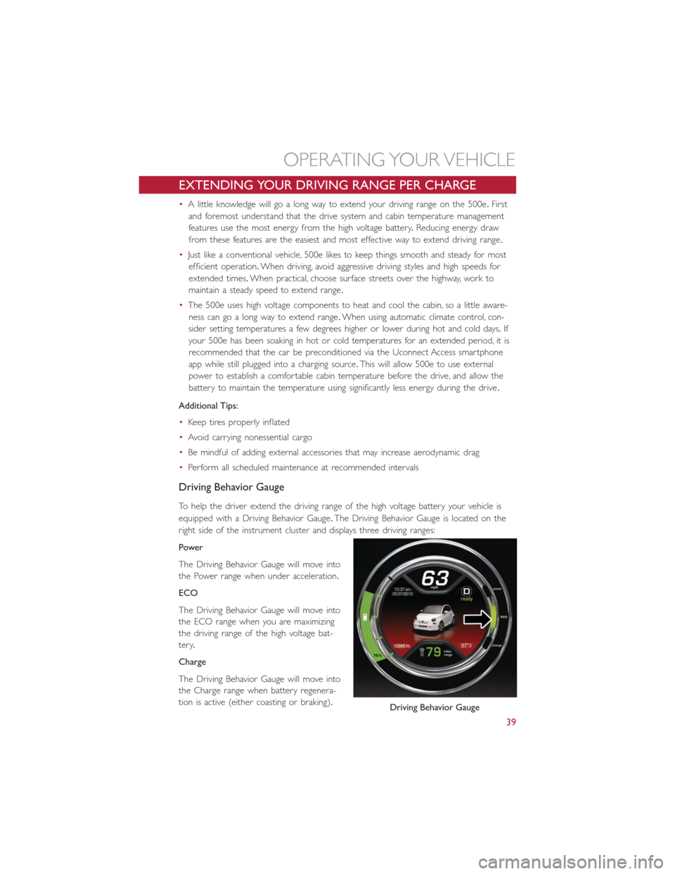
To help the driver extend the driving range of the high voltage battery your vehicle is
equipped with a Driving Behavior Gauge.The Driving Behavior Gauge is located on the
right side of the instrument cluster and displays three driving ranges:
Power
The Driving Behavior Gauge will move into
the Power range when under acceleration.
ECO
The Driving Behavior Gauge will move into
the ECO range when you are maximizing
the driving range of the high voltage bat-
tery.
Charge
The Driving Behavior Gauge will move into
the Charge range when battery regenera-
tion is active (either coasting or braking).
Driving Behavior Gauge
OPERATING YOUR VEHICLE
39
Page 58 of 132
UCONNECT 5.0
NOTE:
Do NOT attach any object to the touchscreen, doing so can result in damage to the
touchscreen.
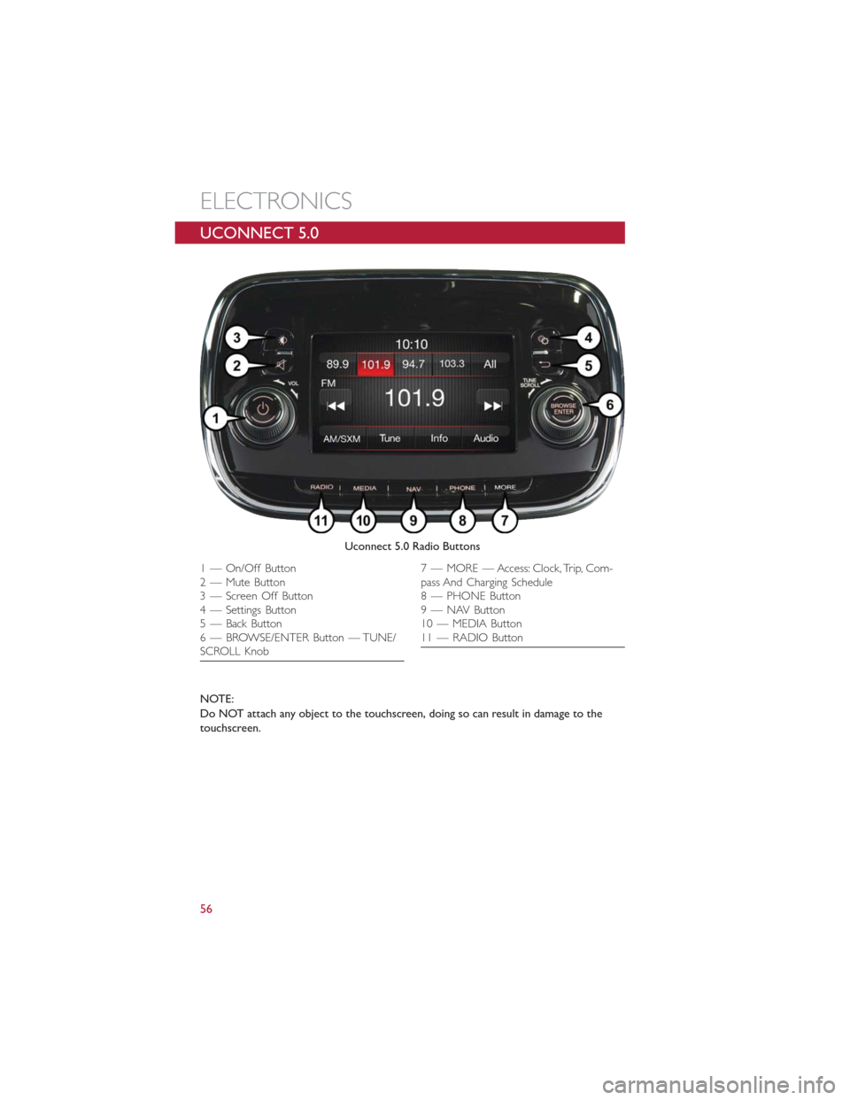
Uconnect 5.0 Radio Buttons
1 — On/Off Button
2 — Mute Button
3 — Screen Off Button
4 — Settings Button
5 — Back Button
6 — BROWSE/ENTER Button — TUNE/
SCROLL Knob7 — MORE — Access: Clock, Trip, Com-
pass And Charging Schedule
8 — PHONE Button
9 — NAV Button
10 — MEDIA Button
11 — RADIO Button
ELECTRONICS
56
Page 80 of 132
PROGRAMMABLE FEATURES
Electronic Vehicle Information Center (EVIC)
•Push theMENUbutton to enter the menu mode.
•Push theUP
orDOWNarrow button to scroll through the menu settings.
•Once the menu setting is shown in the EVIC display push theMENUbutton to access
the setting and use theUP
orDOWNarrow button to change the current
setting.Push theMENUbutton a second time to save the setting and return to menu
screen.
•Battery % Display•Button Volume
•Stored Warnings•Tutorial
•Connectivity ID•Restore Factory Settings
•Exit Menu
Selecting An Option Of The Main Menu Without Submenu:
•Briefly push theMENUbutton to select the main menu option to set.
•Push theUP
orDOWNarrow button to select the new setting.
•Briefly push theMENUbutton to store the new setting and go back to the main
menu option previously selected.
Selecting An Option Of The Main Menu With Submenu:
•Briefly push theMENUbutton to display the first submenu option.
•Push theUP
orDOWNarrow button to scroll through all the submenu op-
tions.
•Briefly push theMENUbutton to select the displayed submenu option and to open
the relevant setup menu.
•Push theUP
orDOWNarrow button to select the new setting for this sub-
menu option.
•Briefly push theMENUbutton to store the new setting and go back to the previously
selected submenu option.
•Push and hold theMENUbutton to return to the main menu (short hold) or the
main screen (longer hold).
NOTE:
The charging schedule is based on the date and time programmed in the EVIC.
ELECTRONICS
78
Page 81 of 132
Uconnect Customer Programmable Features
The Uconnect system allows you to access Customer Programmable feature settings.
To change a setting:
1.Push the SETTINGS
button located on the right side of the display.
2.Select a programmable feature you would like to adjust.
3.Make your selection highlighting the button.
Depending on the vehicles options, the following feature settings are available:
•Display•Audio
•Clock & Date•Phone/Bluetooth
•Safety/Assistance•SiriusXM Setup
•Lights•Voice
•Doors & Locks•Restore Settings
•Engine Off Options•Units
•Clear Personal Data•Charging Schedule
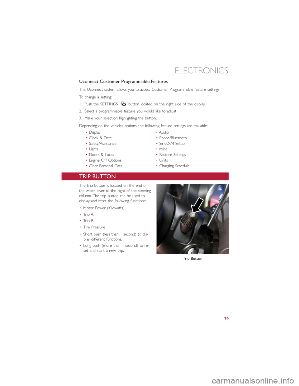
TRIP BUTTON
The Trip button is located on the end of
the wiper lever to the right of the steering
column.The trip button can be used to
display and reset the following functions:
•Motor Power (Kilowatts)
•Trip A
•Trip B
•Tire Pressure
•Short push (less than 1 second) to dis-
play different functions.
•Long push (more than 1 second) to re-
set and start a new trip.
Trip Button
ELECTRONICS
79
Page 85 of 132
ROADSIDE ASSISTANCE
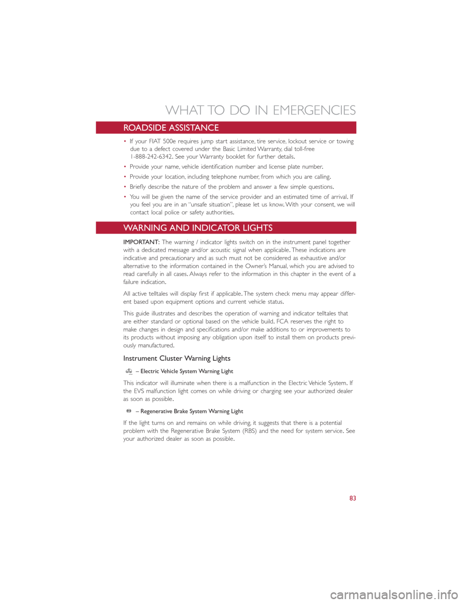
•If your FIAT 500e requires jump start assistance, tire service, lockout service or towing
due to a defect covered under the Basic Limited Warranty, dial toll-free
1-888-242-6342.See your Warranty booklet for further details.
•Provide your name, vehicle identification number and license plate number.
•Provide your location, including telephone number, from which you are calling.
•Briefly describe the nature of the problem and answer a few simple questions.
•You will be given the name of the service provider and an estimated time of arrival.If
you feel you are in an “unsafe situation”, please let us know.With your consent, we will
contact local police or safety authorities.
WARNING AND INDICATOR LIGHTS
IMPORTANT:The warning / indicator lights switch on in the instrument panel together
with a dedicated message and/or acoustic signal when applicable.These indications are
indicative and precautionary and as such must not be considered as exhaustive and/or
alternative to the information contained in the Owner’s Manual, which you are advised to
read carefully in all cases.Always refer to the information in this chapter in the event of a
failure indication.
All active telltales will display first if applicable.The system check menu may appear differ-
ent based upon equipment options and current vehicle status.
This guide illustrates and describes the operation of warning and indicator telltales that
are either standard or optional based on the vehicle build.FCA reserves the right to
make changes in design and specifications and/or make additions to or improvements to
its products without imposing any obligation upon itself to install them on products previ-
ously manufactured.
Instrument Cluster Warning Lights
– Electric Vehicle System Warning Light
This indicator will illuminate when there is a malfunction in the Electric Vehicle System.If
the EVS malfunction light comes on while driving or charging see your authorized dealer
as soon as possible.
– Regenerative Brake System Warning Light
If the light turns on and remains on while driving, it suggests that there is a potential
problem with the Regenerative Brake System (RBS) and the need for system service.See
your authorized dealer as soon as possible.
WHAT TO DO IN EMERGENCIES
83
Page 86 of 132
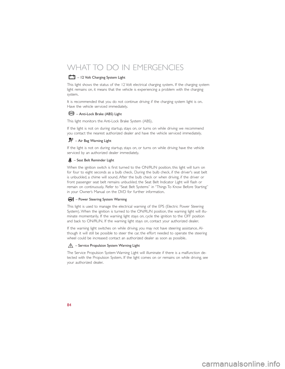
– 12 Volt Charging System Light
This light shows the status of the 12 Volt electrical charging system.If the charging system
light remains on, it means that the vehicle is experiencing a problem with the charging
system.
It is recommended that you do not continue driving if the charging system light is on.
Have the vehicle serviced immediately.
– Anti-Lock Brake (ABS) Light
This light monitors the Anti-Lock Brake System (ABS).
If the light is not on during startup, stays on, or turns on while driving we recommend
you contact the nearest authorized dealer and have the vehicle serviced immediately.
– Air Bag Warning Light
If the light is not on during startup, stays on, or turns on while driving have the vehicle
serviced by an authorized dealer immediately.
– Seat Belt Reminder Light
When the ignition switch is first turned to the ON/RUN position, this light will turn on
for four to eight seconds as a bulb check.During the bulb check, if the driver's seat belt
is unbuckled, a chime will sound.After the bulb check or when driving, if the driver or
front passenger seat belt remains unbuckled, the Seat Belt Indicator Light will flash or
remain on continuously.Refer to “Seat Belt Systems” in “Things To Know Before Starting”
in your Owner’s Manual on the DVD for further information.
– Power Steering System Warning
This light is used to manage the electrical warning of the EPS (Electric Power Steering
System).When the ignition is turned to the ON/RUN position, the warning light will illu-
minate momentarily.If the warning light stays on, cycle the ignition to the OFF position
and back to ON/RUN.If the warning light stays on, contact your authorized dealer.
If the warning light switches on while driving, you may not have steering assistance.Al-
though it will still be possible to steer the car, the effort needed to operate the steering
wheel could be increased: contact an authorized dealer as soon as possible.
– Service Propulsion System Warning Light
The Service Propulsion System Warning Light will illuminate if there is a malfunction de-
tected with the Propulsion System.If the light comes on or remains on while driving, see
your authorized dealer.
WHAT TO DO IN EMERGENCIES
84
Page 99 of 132
WARNING!
•Take care to avoid the radiator cooling fan whenever the hood is raised.It can
start anytime the ignition switch is ON.You can be injured by moving fan blades.
•Remove any metal jewelry such as rings, watch bands and bracelets that could
make an inadvertent electrical contact.You could be seriously injured.
•Batteries contain sulfuric acid that can burn your skin or eyes and generate hydro-
gen gas which is flammable and explosive.Keep open flames or sparks away from
the battery.
1.Set the parking brake, place the transmission into PARK and turn the ignition to
LOCK.
2.Turn off the heater, radio, and all unnecessary electrical accessories.
3.Remove the protective cover over the positive(+)battery post.
4.If using another vehicle to jump-start the battery, park the vehicle within the jumper
cables reach, set the parking brake and make sure the ignition is OFF.
WARNING!
Do not allow vehicles to touch each other as this could establish a ground connection
and personal injury could result.
Jump-Starting Procedure
WARNING!
Failure to follow this jump-starting procedure could result in personal injury or prop-
erty damage due to battery explosion.
CAUTION!
Failure to follow these procedures could result in damage to the charging system of the
booster vehicle or the discharged vehicle.
WHAT TO DO IN EMERGENCIES
97
Page 100 of 132
Connecting The Jumper Cables
1.Connect the positive(+)end of the jumper cable to the positive(+)post of the dis-
charged vehicle.
2.Connect the opposite end of the positive(+)jumper cable to the positive(+)post of
the booster battery.
3.Connect the negative end(-)of the jumper cable to the negative(-)post of the
booster battery.
4.Connect the opposite end of the negative(-)jumper cable to a good engine ground
(exposed metal part of the discharged vehicle underhood compartment) away from
the battery.
WARNING!
Do not connect the jumper cable to the negative(-)post of the discharged battery.
The resulting electrical spark could cause the battery to explode and could result in
personal injury.Only use the specific ground point, do not use any other exposed metal
parts.
5.Start the engine in the vehicle that has the booster battery, let the engine idle a few
minutes, and then turn the key to RUN position on the vehicle with the discharged
battery.
6.Once the vehicle is started, remove the jumper cables in the reverse sequence:
Disconnecting The Jumper Cables
1.Disconnect the negative(-)jumper cable from the engine ground(-)of the vehicle
with the discharged battery.
2.Disconnect the negative end(-)of the jumper cable from the negative(-)post of the
booster battery.
3.Disconnect the opposite end of the positive(+)jumper cable from the positive(+)
post of the booster battery.
4.Disconnect the positive(+)end of the jumper cable from the positive(+)post of the
discharged vehicle.
If frequent jump-starting is required to start your vehicle, you should have the battery
and charging system inspected at your authorized dealer.
WHAT TO DO IN EMERGENCIES
98
Page 114 of 132
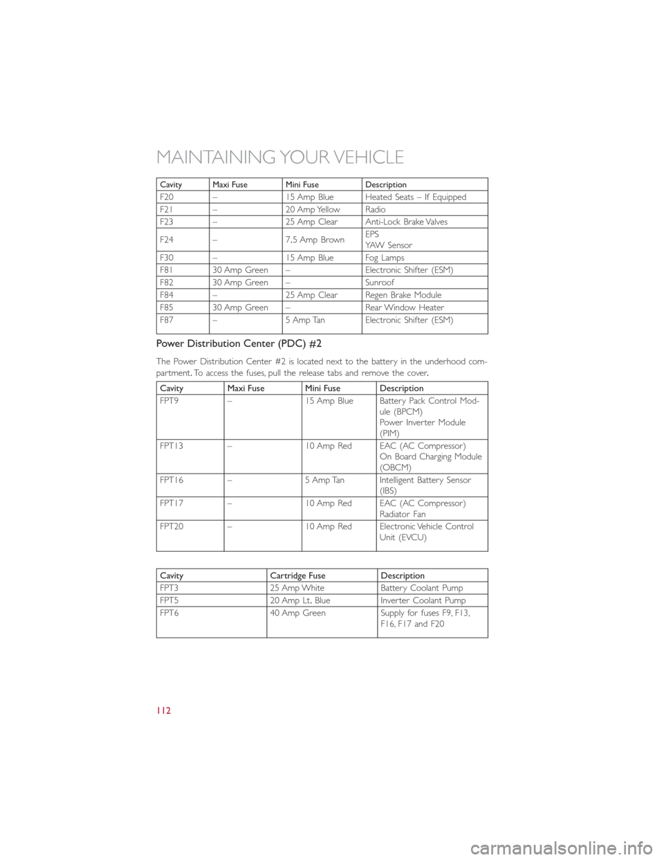
Cavity Maxi Fuse Mini Fuse Description
F20 – 15 Amp Blue Heated Seats – If Equipped
F21 – 20 Amp Yellow Radio
F23 – 25 Amp Clear Anti-Lock Brake Valves
F24 – 7.5 Amp BrownEPS
YAW Sensor
F30 – 15 Amp Blue Fog Lamps
F81 30 Amp Green – Electronic Shifter (ESM)
F82 30 Amp Green – Sunroof
F84 – 25 Amp Clear Regen Brake Module
F85 30 Amp Green – Rear Window Heater
F87 – 5 Amp Tan Electronic Shifter (ESM)
Power Distribution Center (PDC) #2
The Power Distribution Center #2 is located next to the battery in the underhood com-
partment.To access the fuses, pull the release tabs and remove the cover.
Cavity Maxi Fuse Mini Fuse Description
FPT9 – 15 Amp Blue Battery Pack Control Mod-
ule (BPCM)
Power Inverter Module
(PIM)
FPT13 – 10 Amp Red EAC (AC Compressor)
On Board Charging Module
(OBCM)
FPT16 – 5 Amp Tan Intelligent Battery Sensor
(IBS)
FPT17 – 10 Amp Red EAC (AC Compressor)
Radiator Fan
FPT20 – 10 Amp Red Electronic Vehicle Control
Unit (EVCU)
Cavity Cartridge Fuse Description
FPT3 25 Amp White Battery Coolant Pump
FPT5 20 Amp Lt.Blue Inverter Coolant Pump
FPT6 40 Amp Green Supply for fuses F9, F13,
F16, F17 and F20
MAINTAINING YOUR VEHICLE
112
Page 123 of 132
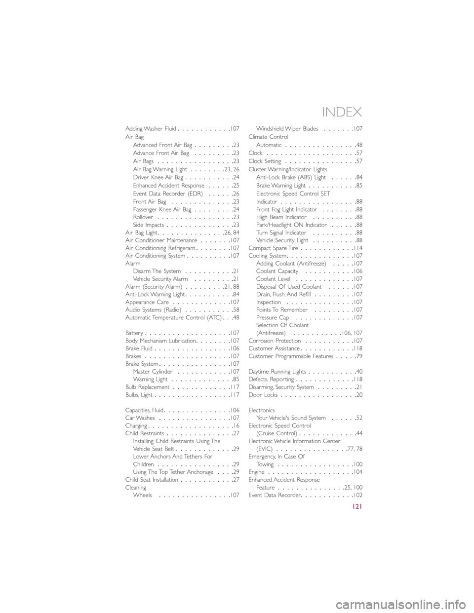
Adding Washer Fluid............107
Air Bag
Advanced Front Air Bag.........23
Advance Front Air Bag.........23
Air Bags.................23
Air Bag Warning Light........23, 26
Driver Knee Air Bag...........24
Enhanced Accident Response......25
Event Data Recorder (EDR)......26
Front Air Bag..............23
Passenger Knee Air Bag.........24
Rollover.................23
Side Impacts...............23
Air Bag Light...............26, 84
Air Conditioner Maintenance.......107
Air Conditioning Refrigerant........107
Air Conditioning System..........107
Alarm
Disarm The System...........21
Vehicle Security Alarm.........21
Alarm (Security Alarm).........21, 88
Anti-Lock Warning Light...........84
Appearance Care.............107
Audio Systems (Radio)...........58
Automatic Temperature Control (ATC)...48
Battery...................107
Body Mechanism Lubrication........107
Brake Fluid.................106
Brakes...................107
Brake System................107
Master Cylinder............107
Warning Light..............85
Bulb Replacement.............117
Bulbs, Light.................117
Capacities, Fluid...............106
Car Washes................107
Charging...................16
Child Restraints...............27
Installing Child Restraints Using The
Vehicle Seat Belt.............29
Lower Anchors And Tethers For
Children.................29
Using The Top Tether Anchorage....29
Child Seat Installation............27
Cleaning
Wheels................107Windshield Wiper Blades.......107
Climate Control
Automatic................48
Clock....................57
Clock Setting................57
Cluster Warning/Indicator Lights
Anti-Lock Brake (ABS) Light......84
Brake Warning Light...........85
Electronic Speed Control SET
Indicator.................88
Front Fog Light Indicator........88
High Beam Indicator..........88
Park/Headlight ON Indicator......88
Turn Signal Indicator..........88
Vehicle Security Light..........88
Compact Spare Tire............114
Cooling System...............107
Adding Coolant (Antifreeze).....107
Coolant Capacity...........106
Coolant Level.............107
Disposal Of Used Coolant......107
Drain, Flush, And Refill.........107
Inspection...............107
Points To Remember.........107
Pressure Cap.............107
Selection Of Coolant
(Antifreeze)...........106, 107
Corrosion Protection...........107
Customer Assistance............
118
Customer Programmable Features.....79
Daytime Running Lights...........40
Defects, Reporting.............118
Disarming, Security System.........21
Door Locks.................20
Electronics
Your Vehicle's Sound System......52
Electronic Speed Control
(Cruise Control).............44
Electronic Vehicle Information Center
(EVIC)................77, 78
Emergency, In Case Of
Towing.................100
Engine...................104
Enhanced Accident Response
Feature...............25, 100
Event Data Recorder............102
INDEX
121