lock FIAT 500E 2016 2.G Owner's Manual
[x] Cancel search | Manufacturer: FIAT, Model Year: 2016, Model line: 500E, Model: FIAT 500E 2016 2.GPages: 132, PDF Size: 4.59 MB
Page 85 of 132
ROADSIDE ASSISTANCE
•If your FIAT 500e requires jump start assistance, tire service, lockout service or towing
due to a defect covered under the Basic Limited Warranty, dial toll-free
1-888-242-6342.See your Warranty booklet for further details.
•Provide your name, vehicle identification number and license plate number.
•Provide your location, including telephone number, from which you are calling.
•Briefly describe the nature of the problem and answer a few simple questions.
•You will be given the name of the service provider and an estimated time of arrival.If
you feel you are in an “unsafe situation”, please let us know.With your consent, we will
contact local police or safety authorities.
WARNING AND INDICATOR LIGHTS
IMPORTANT:The warning / indicator lights switch on in the instrument panel together
with a dedicated message and/or acoustic signal when applicable.These indications are
indicative and precautionary and as such must not be considered as exhaustive and/or
alternative to the information contained in the Owner’s Manual, which you are advised to
read carefully in all cases.Always refer to the information in this chapter in the event of a
failure indication.
All active telltales will display first if applicable.The system check menu may appear differ-
ent based upon equipment options and current vehicle status.
This guide illustrates and describes the operation of warning and indicator telltales that
are either standard or optional based on the vehicle build.FCA reserves the right to
make changes in design and specifications and/or make additions to or improvements to
its products without imposing any obligation upon itself to install them on products previ-
ously manufactured.
Instrument Cluster Warning Lights
– Electric Vehicle System Warning Light
This indicator will illuminate when there is a malfunction in the Electric Vehicle System.If
the EVS malfunction light comes on while driving or charging see your authorized dealer
as soon as possible.
– Regenerative Brake System Warning Light
If the light turns on and remains on while driving, it suggests that there is a potential
problem with the Regenerative Brake System (RBS) and the need for system service.See
your authorized dealer as soon as possible.
WHAT TO DO IN EMERGENCIES
83
Page 86 of 132
– 12 Volt Charging System Light
This light shows the status of the 12 Volt electrical charging system.If the charging system
light remains on, it means that the vehicle is experiencing a problem with the charging
system.
It is recommended that you do not continue driving if the charging system light is on.
Have the vehicle serviced immediately.
– Anti-Lock Brake (ABS) Light
This light monitors the Anti-Lock Brake System (ABS).
If the light is not on during startup, stays on, or turns on while driving we recommend
you contact the nearest authorized dealer and have the vehicle serviced immediately.
– Air Bag Warning Light
If the light is not on during startup, stays on, or turns on while driving have the vehicle
serviced by an authorized dealer immediately.
– Seat Belt Reminder Light
When the ignition switch is first turned to the ON/RUN position, this light will turn on
for four to eight seconds as a bulb check.During the bulb check, if the driver's seat belt
is unbuckled, a chime will sound.After the bulb check or when driving, if the driver or
front passenger seat belt remains unbuckled, the Seat Belt Indicator Light will flash or
remain on continuously.Refer to “Seat Belt Systems” in “Things To Know Before Starting”
in your Owner’s Manual on the DVD for further information.
– Power Steering System Warning
This light is used to manage the electrical warning of the EPS (Electric Power Steering
System).When the ignition is turned to the ON/RUN position, the warning light will illu-
minate momentarily.If the warning light stays on, cycle the ignition to the OFF position
and back to ON/RUN.If the warning light stays on, contact your authorized dealer.
If the warning light switches on while driving, you may not have steering assistance.Al-
though it will still be possible to steer the car, the effort needed to operate the steering
wheel could be increased: contact an authorized dealer as soon as possible.
– Service Propulsion System Warning Light
The Service Propulsion System Warning Light will illuminate if there is a malfunction de-
tected with the Propulsion System.If the light comes on or remains on while driving, see
your authorized dealer.
WHAT TO DO IN EMERGENCIES
84
Page 87 of 132
– Brake Warning Light
This light monitors various brake functions, including brake fluid level and parking brake
application.If the brake light turns on, it may indicate that the parking brake is applied,
that the brake fluid level is low, or that there is a problem with the brake system master
cylinder reservoir.
If the light remains on when the parking brake has been disengaged, and the fluid level is
at the full mark on the master cylinder reservoir, it indicates a possible brake hydraulic
system malfunction or that a problem with the Brake Booster has been detected by the
Anti-Lock Brake System (ABS)/Electronic Stability Control (ESC) system.In this case, the
light will remain on until the condition has been corrected.If the problem is related to
the brake booster, the ABS pump will run when applying the brake, and a brake pedal
pulsation may be felt during each stop.
The dual brake system provides a reserve braking capacity in the event of a failure to a
portion of the hydraulic system.A leak in either half of the dual brake system is indicated
by the Brake Warning Light, which will turn on when the brake fluid level in the master
cylinder has dropped below a specified level.The light will remain on until the cause is
corrected.
Vehicles equipped with the Anti-Lock Brake System (ABS) are also equipped with Elec-
tronic Brake Force Distribution (EBD).In the event of an EBD failure, the Brake Warning
Light will turn on along with the ABS Light.Immediate repair to the ABS system is re-
quired.
Operation of the Brake Warning Light can be checked by turning the ignition switch from
the OFF position to the ON/RUN position.The light should illuminate for approximately
two seconds.The light should then turn off unless the parking brake is applied or a brake
fault is detected.If the light does not illuminate, have the light inspected by an authorized
dealer.
The light also will turn on when the parking brake is applied with the ignition switch in
the ON/RUN position.
NOTE:
This light shows only that the parking brake is applied.It does not show the degree of
brake application.
WARNING!
Driving a vehicle with the red brake light on is dangerous.Part of the brake system
may have failed.It will take longer to stop the vehicle.You could have a collision.Have
the vehicle checked immediately.
WHAT TO DO IN EMERGENCIES
85
Page 97 of 132
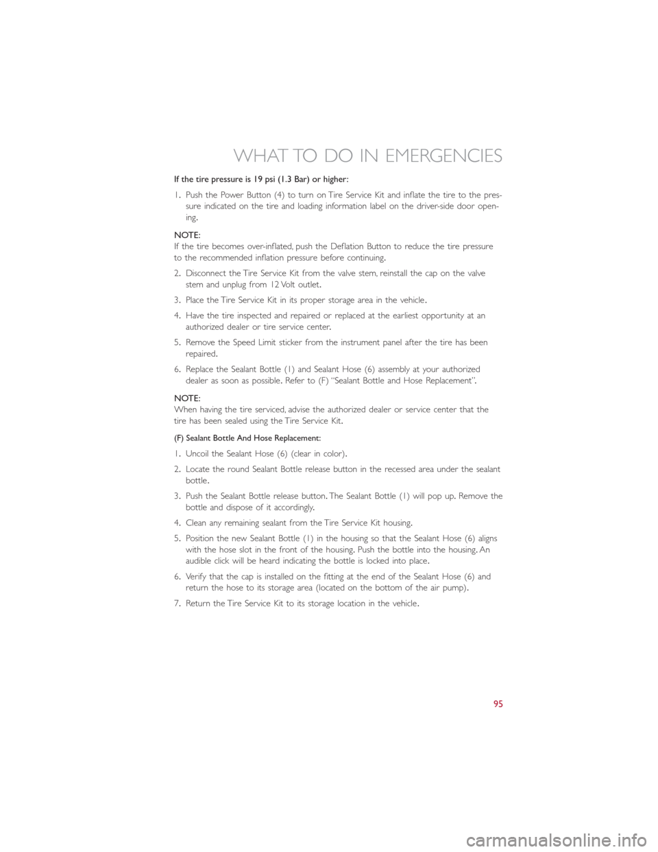
If the tire pressure is 19 psi (1.3 Bar) or higher:
1.Push the Power Button (4) to turn on Tire Service Kit and inflate the tire to the pres-
sure indicated on the tire and loading information label on the driver-side door open-
ing.
NOTE:
If the tire becomes over-inflated, push the Deflation Button to reduce the tire pressure
to the recommended inflation pressure before continuing.
2.Disconnect the Tire Service Kit from the valve stem, reinstall the cap on the valve
stem and unplug from 12 Volt outlet.
3.Place the Tire Service Kit in its proper storage area in the vehicle.
4.Have the tire inspected and repaired or replaced at the earliest opportunity at an
authorized dealer or tire service center.
5.Remove the Speed Limit sticker from the instrument panel after the tire has been
repaired.
6.Replace the Sealant Bottle (1) and Sealant Hose (6) assembly at your authorized
dealer as soon as possible.Refer to (F) “Sealant Bottle and Hose Replacement”.
NOTE:
When having the tire serviced, advise the authorized dealer or service center that the
tire has been sealed using the Tire Service Kit.
(F) Sealant Bottle And Hose Replacement:
1.Uncoil the Sealant Hose (6) (clear in color).
2.Locate the round Sealant Bottle release button in the recessed area under the sealant
bottle.
3.Push the Sealant Bottle release button.The Sealant Bottle (1) will pop up.Remove the
bottle and dispose of it accordingly.
4.Clean any remaining sealant from the Tire Service Kit housing.
5.Position the new Sealant Bottle (1) in the housing so that the Sealant Hose (6) aligns
with the hose slot in the front of the housing.Push the bottle into the housing.An
audible click will be heard indicating the bottle is locked into place.
6.Verify that the cap is installed on the fitting at the end of the Sealant Hose (6) and
return the hose to its storage area (located on the bottom of the air pump).
7.Return the Tire Service Kit to its storage location in the vehicle.
WHAT TO DO IN EMERGENCIES
95
Page 99 of 132
WARNING!
•Take care to avoid the radiator cooling fan whenever the hood is raised.It can
start anytime the ignition switch is ON.You can be injured by moving fan blades.
•Remove any metal jewelry such as rings, watch bands and bracelets that could
make an inadvertent electrical contact.You could be seriously injured.
•Batteries contain sulfuric acid that can burn your skin or eyes and generate hydro-
gen gas which is flammable and explosive.Keep open flames or sparks away from
the battery.
1.Set the parking brake, place the transmission into PARK and turn the ignition to
LOCK.
2.Turn off the heater, radio, and all unnecessary electrical accessories.
3.Remove the protective cover over the positive(+)battery post.
4.If using another vehicle to jump-start the battery, park the vehicle within the jumper
cables reach, set the parking brake and make sure the ignition is OFF.
WARNING!
Do not allow vehicles to touch each other as this could establish a ground connection
and personal injury could result.
Jump-Starting Procedure
WARNING!
Failure to follow this jump-starting procedure could result in personal injury or prop-
erty damage due to battery explosion.
CAUTION!
Failure to follow these procedures could result in damage to the charging system of the
booster vehicle or the discharged vehicle.
WHAT TO DO IN EMERGENCIES
97
Page 101 of 132
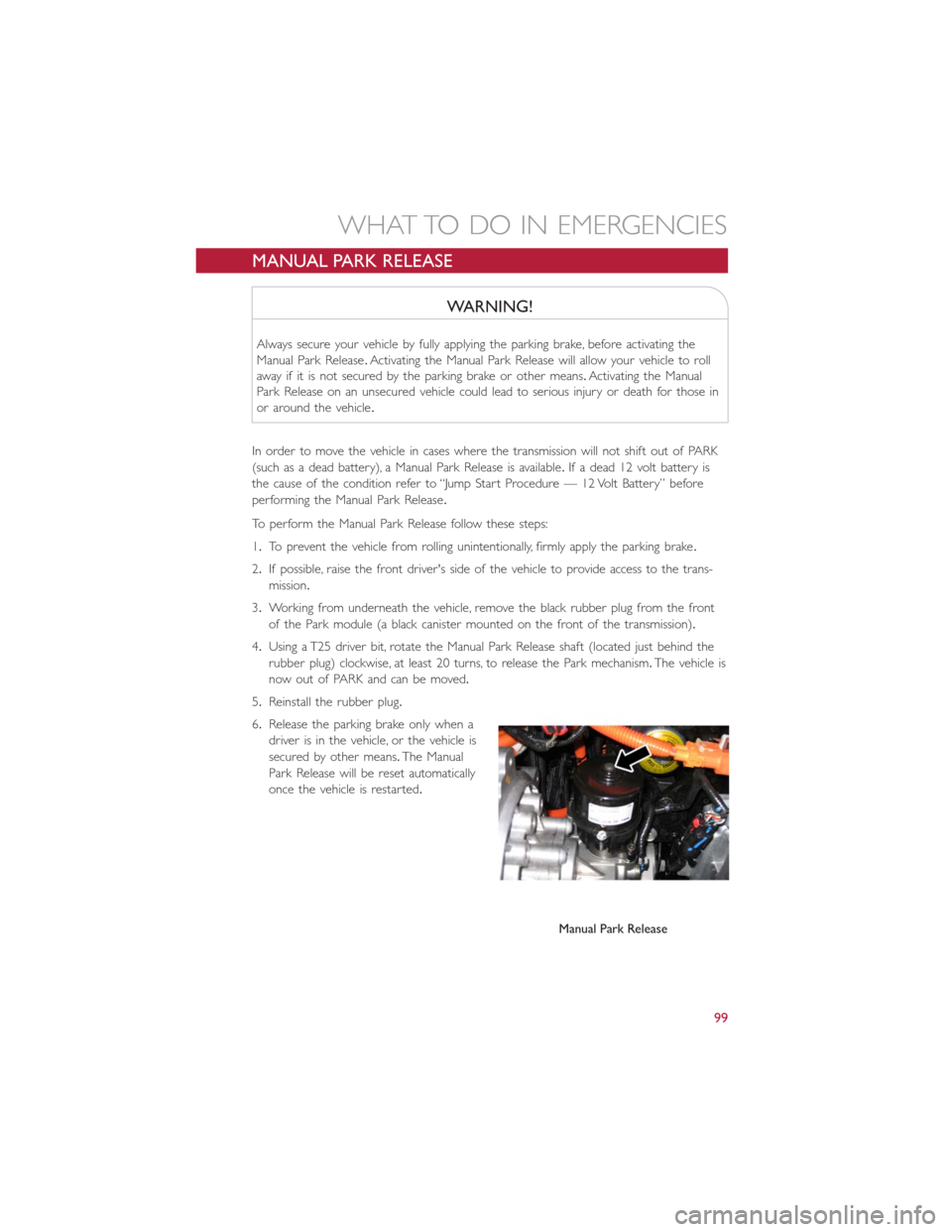
MANUAL PARK RELEASE
WARNING!
Always secure your vehicle by fully applying the parking brake, before activating the
Manual Park Release.Activating the Manual Park Release will allow your vehicle to roll
away if it is not secured by the parking brake or other means.Activating the Manual
Park Release on an unsecured vehicle could lead to serious injury or death for those in
or around the vehicle.
In order to move the vehicle in cases where the transmission will not shift out of PARK
(such as a dead battery), a Manual Park Release is available.Ifadead12voltbatteryis
the cause of the condition refer to “Jump Start Procedure — 12 Volt Battery” before
performing the Manual Park Release.
To perform the Manual Park Release follow these steps:
1.To prevent the vehicle from rolling unintentionally, firmly apply the parking brake.
2.If possible, raise the front driver's side of the vehicle to provide access to the trans-
mission.
3.Working from underneath the vehicle, remove the black rubber plug from the front
of the Park module (a black canister mounted on the front of the transmission).
4.Using a T25 driver bit, rotate the Manual Park Release shaft (located just behind the
rubber plug) clockwise, at least 20 turns, to release the Park mechanism.The vehicle is
now out of PARK and can be moved.
5.Reinstall the rubber plug.
6.Release the parking brake only when a
driver is in the vehicle, or the vehicle is
secured by other means.The Manual
Park Release will be reset automatically
once the vehicle is restarted.
Manual Park Release
WHAT TO DO IN EMERGENCIES
99
Page 102 of 132
TOWING A DISABLED VEHICLE
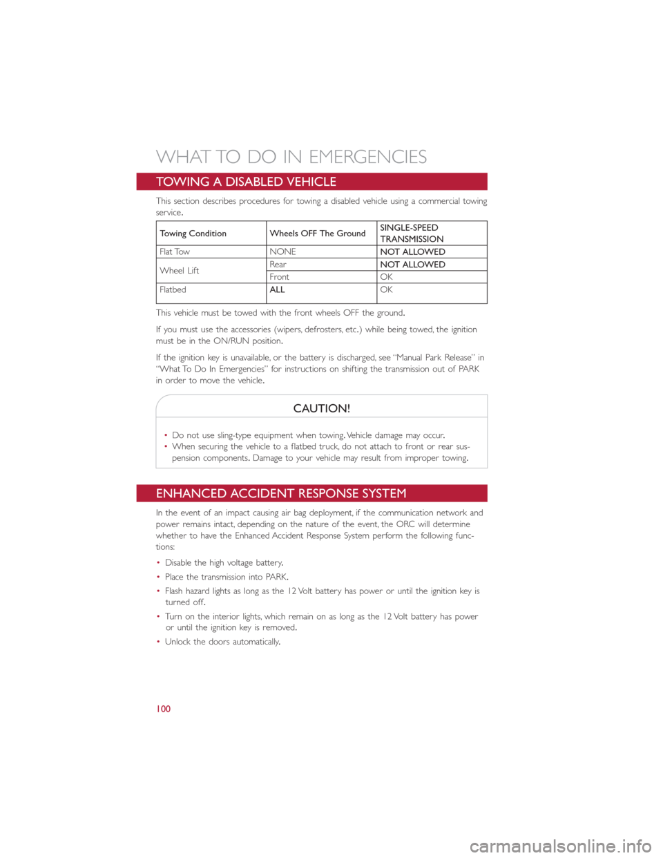
This section describes procedures for towing a disabled vehicle using a commercial towing
service.
Towing Condition Wheels OFF The GroundSINGLE-SPEED
TRANSMISSION
Flat Tow NONE
NOT ALLOWED
Wheel LiftRear
NOT ALLOWED
Front OK
Flatbed
ALLOK
This vehicle must be towed with the front wheels OFF the ground.
If you must use the accessories (wipers, defrosters, etc.) while being towed, the ignition
must be in the ON/RUN position.
If the ignition key is unavailable, or the battery is discharged, see “Manual Park Release” in
“What To Do In Emergencies” for instructions on shifting the transmission out of PARK
in order to move the vehicle.
CAUTION!
•Do not use sling-type equipment when towing.Vehicle damage may occur.
•When securing the vehicle to a flatbed truck, do not attach to front or rear sus-
pension components.Damage to your vehicle may result from improper towing.
ENHANCED ACCIDENT RESPONSE SYSTEM
In the event of an impact causing air bag deployment, if the communication network and
power remains intact, depending on the nature of the event, the ORC will determine
whether to have the Enhanced Accident Response System perform the following func-
tions:
•Disable the high voltage battery.
•Place the transmission into PARK.
•Flash hazard lights as long as the 12 Volt battery has power or until the ignition key is
turned off.
•Turn on the interior lights, which remain on as long as the 12 Volt battery has power
or until the ignition key is removed.
•Unlock the doors automatically.
WHAT TO DO IN EMERGENCIES
100
Page 105 of 132
OPENING THE HOOD
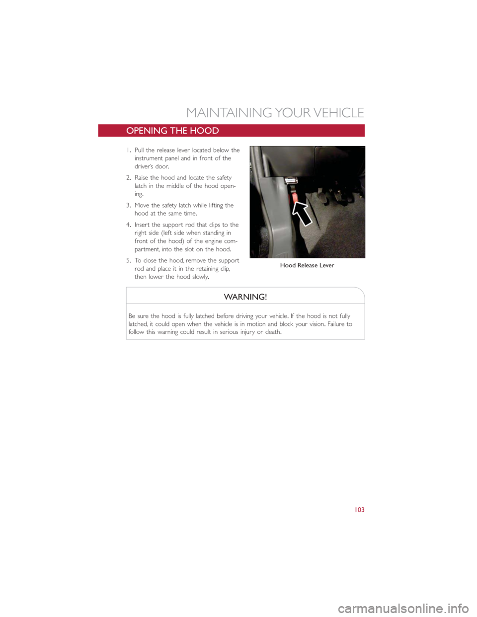
1.Pull the release lever located below the
instrument panel and in front of the
driver’s door.
2.Raise the hood and locate the safety
latch in the middle of the hood open-
ing.
3.Move the safety latch while lifting the
hood at the same time.
4.Insert the support rod that clips to the
right side (left side when standing in
front of the hood) of the engine com-
partment, into the slot on the hood.
5.To close the hood, remove the support
rod and place it in the retaining clip,
then lower the hood slowly.
WARNING!
Be sure the hood is fully latched before driving your vehicle.If the hood is not fully
latched, it could open when the vehicle is in motion and block your vision.Failure to
follow this warning could result in serious injury or death.
Hood Release Lever
MAINTAINING YOUR VEHICLE
103
Page 112 of 132
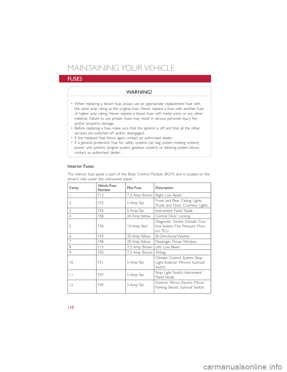
FUSES
WARNING!
•When replacing a blown fuse, always use an appropriate replacement fuse with
the same amp rating as the original fuse.Never replace a fuse with another fuse
of higher amp rating.Never replace a blown fuse with metal wires or any other
material.Failure to use proper fuses may result in serious personal injury, fire
and/or property damage.
•Before replacing a fuse, make sure that the ignition is off and that all the other
services are switched off and/or disengaged.
•If the replaced fuse blows again, contact an authorized dealer.
•If a general protection fuse for safety systems (air bag system, braking system),
power unit systems (engine system, gearbox system) or steering system blows,
contact an authorized dealer.
Interior Fuses
The interior fuse panel is part of the Body Control Module (BCM) and is located on the
driver's side under the instrument panel.
CavityVehicle Fuse
NumberMini Fuse Description
1 F12 7.5 Amp Brown Right Low Beam
2 F32 5 Amp TanFront and Rear Ceiling Lights
Trunk and Door Courtesy Lights
3 F53 5 Amp Tan Instrument Panel Node
4 F38 20 Amp Yellow Central Door Locking
5 F36 10 Amp RedDiagnostic Socket, Climate Con-
trol System, Tire Pressure Moni-
tor, TCU
6 F43 20 Amp Yellow Bi-Directional Washer
7 F48 20 Amp Yellow Passenger Power Window
8 F13 7.5 Amp Brown Left Low Beam
9 F50 7.5 Amp Brown Airbag
10 F51 5 Amp TanClimate Control System, Stop
Light, Exterior Mirrors, Sunroof
Switch
11 F37 5 Amp TanStop Light Switch, Instrument
Panel Node
12 F49 5 Amp TanExterior Mirror, Electric Mirror,
Parking Sensor, Sunroof Switch
MAINTAINING YOUR VEHICLE
110
Page 113 of 132
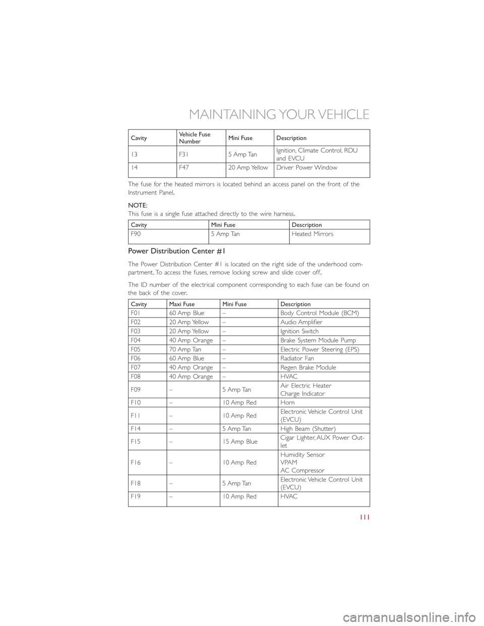
CavityVehicle Fuse
NumberMini Fuse Description
13 F31 5 Amp TanIgnition, Climate Control, RDU
and EVCU
14 F47 20 Amp Yellow Driver Power Window
The fuse for the heated mirrors is located behind an access panel on the front of the
Instrument Panel.
NOTE:
This fuse is a single fuse attached directly to the wire harness.
Cavity Mini Fuse Description
F90 5 Amp Tan Heated Mirrors
Power Distribution Center #1
The Power Distribution Center #1 is located on the right side of the underhood com-
partment.To access the fuses, remove locking screw and slide cover off.
The ID number of the electrical component corresponding to each fuse can be found on
thebackofthecover.
Cavity Maxi Fuse Mini Fuse Description
F01 60 Amp Blue – Body Control Module (BCM)
F02 20 Amp Yellow – Audio Amplifier
F03 20 Amp Yellow – Ignition Switch
F04 40 Amp Orange – Brake System Module Pump
F05 70 Amp Tan – Electric Power Steering (EPS)
F06 60 Amp Blue – Radiator Fan
F07 40 Amp Orange – Regen Brake Module
F08 40 Amp Orange – HVAC
F09 – 5 Amp TanAir Electric Heater
Charge Indicator
F10 – 10 Amp Red Horn
F11 – 10 Amp RedElectronic Vehicle Control Unit
(EVCU)
F14 – 5 Amp Tan High Beam (Shutter)
F15 – 15 Amp BlueCigar Lighter, AUX Power Out-
let
F16 – 10 Amp RedHumidity Sensor
VPAM
AC Compressor
F18 – 5 Amp TanElectronic Vehicle Control Unit
(EVCU)
F19 – 10 Amp Red HVAC
MAINTAINING YOUR VEHICLE
111