stop start FIAT 500E 2016 2.G User Guide
[x] Cancel search | Manufacturer: FIAT, Model Year: 2016, Model line: 500E, Model: FIAT 500E 2016 2.GPages: 132, PDF Size: 4.59 MB
Page 19 of 132
NOTE:
•The vehicle will initiate the charging cycle automatically when all the conditions are
satisfied.
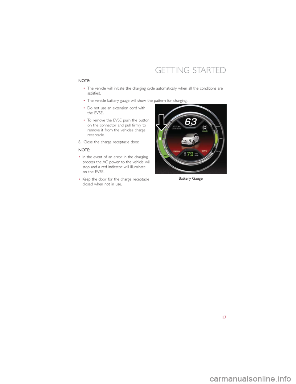
•The vehicle battery gauge will show the pattern for charging.
•Do not use an extension cord with
the EVSE.
•To remove the EVSE push the button
on the connector and pull firmly to
remove it from the vehicle’s charge
receptacle.
8.Close the charge receptacle door.
NOTE:
•In the event of an error in the charging
process the AC power to the vehicle will
stop and a red indicator will illuminate
on the EVSE.
•Keep the door for the charge receptacle
closed when not in use.
Battery Gauge
GETTING STARTED
17
Page 24 of 132
SEAT BELT SYSTEMS
Lap/Shoulder Belts
All seating positions in your vehicle are equipped with lap/shoulder belts.
Be sure everyone in your vehicle is in a seat and using a seat belt properly.
Position the lap belt so that it is snug and lies low across your hips, below your abdomen.
To remove slack in the lap belt portion, pull up on the shoulder belt.To loosen the lap
belt if it is too tight, tilt the latch plate and pull on the lap belt.A snug seat belt reduces
the risk of sliding under the seat belt in a collision.
Position the shoulder belt across the shoulder and chest with minimal, if any slack so that
it is comfortable and not resting on your neck.The retractor will withdraw any slack in
the shoulder belt.
Seat Belt Pretensioner
The front seat belt system is equipped with pretensioning devices that are designed to
remove slack from the seat belt in the event of a collision.
A deployed pretensioner or a deployed air bag must be replaced immediately.
WARNING!
•In a collision, you and your passengers can suffer much greater injuries if you are
not properly buckled up.You can strike the interior of your vehicle or other pas-
sengers, or you can be thrown out of the vehicle.Always be sure you and others
in your vehicle are buckled up properly.
•A shoulder belt placed behind you will not protect you from injury during a colli-
sion.You are more likely to hit your head in a collision if you do not wear your
shoulder belt.The lap and shoulder belt are meant to be used together.
•A seat belt that is too loose will not protect you properly.In a sudden stop, you
could move too far forward, increasing the possibility of injury.Wear your seat belt
snugly.
•A frayed or torn seat belt could rip apart in a collision and leave you with no pro-
tection.Inspect the seat belt system periodically, checking for cuts, frays, or loose
parts.Damaged parts must be replaced immediately.Do not disassemble or
modify the system.Seat belt assemblies must be replaced after a collision.
GETTING STARTED
22
Page 28 of 132
Air Bag Warning Light
The air bags must be ready to inflate for your protection in a collision.The Occupant
Restraint Controller (ORC) monitors the internal circuits and interconnecting wiring asso-
ciated with air bag system electrical components.
The ORC monitors the readiness of the electronic parts of the air bag system whenever
the ignition switch is in the AVV or MAR position.If the ignition switch is in the STOP
position the air bag system is not on and the air bags will not inflate.
The ORC turns on the Air Bag Warning Light in the instrument panel for approximately
four to eight seconds for a self-check when the ignition switch is first turned to the MAR
position.After the self-check, the Air Bag Warning Light will turn off.If the ORC detects
a malfunction in any part of the system, it turns on the Air Bag Warning Light, either mo-
mentarily or continuously.A single chime will sound to alert you if the light comes on
again after initial startup.
If the Air Bag Warning Light in the instrument panel is not on during the four to eight
seconds when the ignition switch is first turned to the MAR position, stays on, or turns
on while driving, have the vehicle serviced by an authorized service center immediately.
NOTE:
If the speedometer, tachometer (if equipped), or any engine related gauges are not work-
ing, the Occupant Restraint Controller (ORC) may also be disabled.In this condition the
air bags may not be ready to inflate for your protection.Have an authorized dealer ser-
vice the air bag system immediately.
Event Data Recorder (EDR)
This vehicle is equipped with an event data recorder (EDR).The main purpose of an
EDR is to record, in certain crash or near crash-like situations, such as an air bag deploy-
ment or hitting a road obstacle, data that will assist in understanding how a vehicle’s sys-
tems performed.The EDR is designed to record data related to vehicle dynamics and
safety systems for a short period of time, typically 30 seconds or less.The EDR in this
vehicle is designed to record such data as:
•How various systems in your vehicle were operating;
•Whether or not the driver and passenger safety belts were buckled/fastened;
•How far (if at all) the driver was depressing the accelerator and/or brake pedal; and,
•How fast the vehicle was traveling.
GETTING STARTED
26
Page 34 of 132
Reactive Head Restraints — Front Seats
The front driver and passenger seats are equipped with Reactive Head Restraints.In the
event of a rear impact the Reactive Head Restraints will automatically extend forward
minimizing the gap between the back of the occupant's head and the Reactive Head Re-
straint.
To raise the head restraint, pull upward on the head restraint.To lower the head re-
straint, push the adjustment button, located at the base of the head restraint, and push
downward on the head restraint.
The Reactive Head Restraints will automatically return to their normal position following a
rear impact.If the Reactive Head Restraints do not return to their normal position, see
your authorized dealership immediately.
NOTE:
The head restraints should only be removed by qualified technicians, for service purposes
only.If either of the head restraints require removal, see your authorized dealership.
WARNING!
•A loose head restraint thrown forward in a collision or hard stop could cause seri-
ous injury or death to occupants of the vehicle.Always securely stow removed
head restraints in a location outside the occupant compartment.
•ALL the head restraints MUST be reinstalled in the vehicle to properly protect
the occupants.Follow the re-installation instructions above prior to operating the
vehicle or occupying a seat.
•Do not place items over the top of the Reactive Head Restraint, such as coats,
seat covers or portable DVD players.These items may interfere with the opera-
tion of the Reactive Head Restraint in the event of a collision and could result in
serious injury or death.
Rear Head Restraints
To raise the head restraint, pull upward on the head restraint.To lower the head re-
straint, push the adjustment button, located at the base of the head restraint, and push
downward on the head restraint.Refer to “Occupant Restraints” in “Things To Know Be-
fore Starting Your Vehicle” in your Owner’s Manual on the DVD for further information
on tether routing.
NOTE:
To remove the head restraint, raise it as far as it can go then push the release button and
the adjustment button at the base of each post while pulling the head restraint up.To
reinstall the head restraint, put the head restraint posts into the holes and push down-
ward.Then adjust the head restraint to the appropriate height.
GETTING STARTED
32
Page 88 of 132

– Tire Pressure Monitoring System (TPMS) Light
Each tire, including the spare (if provided), should be checked monthly when cold and
inflated to the inflation pressure recommended by the vehicle manufacturer on the ve-
hicle placard or tire inflation pressure label.(If your vehicle has tires of a different size
than the size indicated on the vehicle placard or tire inflation pressure label, you should
determine the proper tire inflation pressure for those tires.)
As an added safety feature, your vehicle has been equipped with a Tire Pressure Monitor-
ing System (TPMS) that illuminates a low tire pressure telltale when one or more of your
tires is significantly under-inflated.Accordingly, when the low tire pressure telltale illumi-
nates, you should stop and check your tires as soon as possible, and inflate them to the
proper pressure.Driving on a significantly under-inflated tire causes the tire to overheat
and can lead to tire failure.Under-inflation also increases high voltage battery consump-
tion and tire tread life, and may affect the vehicle’s handling and stopping ability.
IF THE LIGHT STARTS FLASHING INDICATING A LOW TIRE PRESSURE, ADJUST
THE AIR PRESSURE IN THE LOW TIRE TO THE AIR PRESSURE SHOWN ON THE
VEHICLE PLACARD OR TIRE INFLATION PRESSURE LABEL LOCATED ON THE
DRIVER'S DOOR.
NOTE:
After inflation, the vehicle may need to be driven for 20 minutes before the flashing light
will turn off.
Please note that the TPMS is not a substitute for proper tire maintenance, and it is the
driver’s responsibility to maintain correct tire pressure, even if under-inflation has not
reached the level to trigger illumination of the TPMS low tire pressure telltale.
Your vehicle has also been equipped with a TPMS malfunction indicator to indicate when
the system is not operating properly.The TPMS malfunction indicator is combined with
the low tire pressure telltale.When the system detects a malfunction, the telltale will
flash for approximately one minute and then remain continuously illuminated.This se-
quence will continue upon subsequent vehicle start-ups as long as the malfunction exists.
When the malfunction indicator is illuminated, the system may not be able to detect or
signal low tire pressure as intended.TPMS malfunctions may occur for a variety of rea-
sons, including the installation of replacement or alternate tires or wheels on the vehicle
that prevent the TPMS from functioning properly.Always check the TPMS malfunction
telltale after replacing one or more tires or wheels on your vehicle, to ensure that the
replacement or alternate tires and wheels allow the TPMS to continue to function prop-
erly.
WHAT TO DO IN EMERGENCIES
86
Page 94 of 132
Sealing A Tire With Tire Service Kit
(A) Whenever You Stop To Use Tire Service Kit:
1.Pull over to a safe location and turn on the vehicle’s Hazard Warning flashers.
2.Verify that the valve stem (on the wheel with the deflated tire) is in a position that is
near to the ground.This will allow the Tire Service Kit Hoses (6) and (7) to reach the
valve stem and keep the Tire Service Kit flat on the ground.This will provide the best
positioning of the kit when injecting the sealant into the deflated tire and running the
air pump.Move the vehicle as necessary to place the valve stem in this position be-
fore proceeding.
3.Place the transmission in PARK (auto transmission) or in Gear (manual transmission)
and place the ignition in the OFF position.
4.Set the parking brake.
(B) Setting Up To Use Tire Service Kit:
1.Push in the Mode Select Knob (5) and turn to the Sealant Mode position.
2.Uncoil the Sealant Hose (6) and then remove the cap from the fitting at the end of
the hose.
3.Place the Tire Service Kit flat on the ground next to the deflated tire.
4.Remove the cap from the valve stem and then screw the fitting at the end of the
Sealant Hose (6) onto the valve stem.
5.Uncoil the Power Plug (8) and insert the plug into the vehicle’s 12 Volt power outlet.
NOTE:
Do not remove foreign objects (e.g., screws or nails) from the tire.
(C) Injecting Tire Service Kit Sealant Into The Deflated Tire:
•Always start the engine before turning ON the Tire Service Kit.
NOTE:
Manual transmission vehicles must have the parking brake engaged and the gear selector
in NEUTRAL.
•After pushing the Power Button (4), the sealant (white fluid) will flow from the Sealant
Bottle (1) through the Sealant Hose (6) and into the tire.
NOTE:
Sealant may leak out through the puncture in the tire.
WHAT TO DO IN EMERGENCIES
92
Page 103 of 132
In order to move your vehicle to the side of the road the transmission must be in NEU-
TRAL and the 12 Volt system must be functional.To place the transmission into NEU-
TRAL you must turn the ignition OFF and then back to the RUN position (cycle the igni-
tion) then push the NEUTRAL button.
NOTE:
The high voltage battery will remain disabled after an Enhanced Accident Response Event
and must be reset by your authorized dealership.
FREEING A STUCK VEHICLE
If your vehicle becomes stuck in mud, sand or snow, it can often be moved using a rock-
ing motion.Turn the steering wheel right and left to clear the area around the front
wheels.Then shift back and forth between DRIVE and REVERSE while gently pushing the
accelerator.Use the least amount of accelerator pedal pressure that will maintain the
rocking motion, without spinning the wheels.
NOTE:
Push the “ESC Off ” switch, to place the Electronic Stability Control (ESC) system in “Par-
tial Off ” mode, before rocking the vehicle.Refer to “Electronic Brake Control” in “Start-
ing And Operating” on the DVD for further information.Once the vehicle has been
freed, push the “ESC Off ” switch again to restore “ESC On” mode.
CAUTION!
•When “rocking” a stuck vehicle by shifting between DRIVE and REVERSE, do not
spin the wheels faster than 15 mph (24 km/h), or drivetrain damage may result.
•Spinning the wheels too fast may lead to transmission overheating and failure.It
can also damage the tires.Do not spin the wheels above 30 mph (48 km/h) while
in gear.
WARNING!
Fast spinning tires can be dangerous.Forces generated by excessive wheel speeds may
cause damage, or even failure, of the axle and tires.A tire could explode and injure
someone.Do not spin your vehicle's wheels faster than 30 mph (48 km/h) or for lon-
ger than 30 seconds continuously without stopping when you are stuck and do not let
anyone near a spinning wheel, no matter what the speed.
WHAT TO DO IN EMERGENCIES
101