maintenance FIAT 500E 2018 Owners Manual
[x] Cancel search | Manufacturer: FIAT, Model Year: 2018, Model line: 500E, Model: FIAT 500E 2018Pages: 302, PDF Size: 3.32 MB
Page 3 of 302
TABLE OF CONTENTSSECTIONPAGE
1INTRODUCTION
...................................................................3
2GRAPHICAL TABLE OF CONTENTS
......................................................7
3GETTING TO KNOW YOUR VEHICLE
...................................................13
4GETTING TO KNOW YOUR INSTRUMENT PANEL .
.........................................83
5SAFETY
........................................................................\
..99
6STARTINGANDOPERATING.........................................................153
7INCASEOFEMERGENCY ...........................................................179
8SERVICING AND MAINTENANCE
.....................................................213
9TECHNICAL SPECIFICATIONS
........................................................255
10MULTIMEDIA ....................................................................261
11CUSTOMER ASSISTANCE
............................................................283
12INDEX........................................................................\
..289
1
2
3
4
5
6
7
8
9
10 11
12
Page 6 of 302
INTRODUCTION
Congratulations on selecting your new FIAT 500e. Be
assured that your 500e represents an elegant marriage of
technology and Italian styling that is as good for the
environment as it is fun to drive!
This Owner’s Manual has been prepared with the assis-
tance of service and engineering specialists to acquaint you
with the operation, understanding and maintenance of
your 500e. It is supplemented by Warranty Information,
and various customer-oriented documents. Please take the
time to read these publications carefully. Following the
instructions and recommendations in this manual will help
assure safe and enjoyable operation of your vehicle.
The enclosed Warranty Information lists the services that
FCA US LLC offers to its customers:
•The Warranty Certificate with terms and conditions for
maintaining its validity
• The range of additional services available to FCA US
LLC customers
NOTE: After reviewing the owner information, it should
be stored in the vehicle for convenient referencing and
remain with the vehicle when sold. When it comes to service, remember that your authorized
dealer knows your vehicle best, has factory-trained techni-
cians and genuine MOPAR® parts, and cares about your
satisfaction.
HOW TO USE THIS MANUAL
Essential Information
Consult the Table of Contents to determine which section
contains the information you desire.
Since the specification of your vehicle depends on the items
of equipment ordered, certain descriptions and illustra-
tions may differ from your vehicle’s equipment.
The detailed index at the back of this Owner’s Manual
contains a complete listing of all subjects.
Symbols
Some vehicle components have colored labels whose sym-
bols indicate precautions to be observed when using this
component. Refer to “Warning Lights and Messages” in
“Getting To Know Your Instrument Panel” for further
information on the symbols used in your vehicle.
4 INTRODUCTION
Page 18 of 302
HIGH VOLTAGE BATTERY
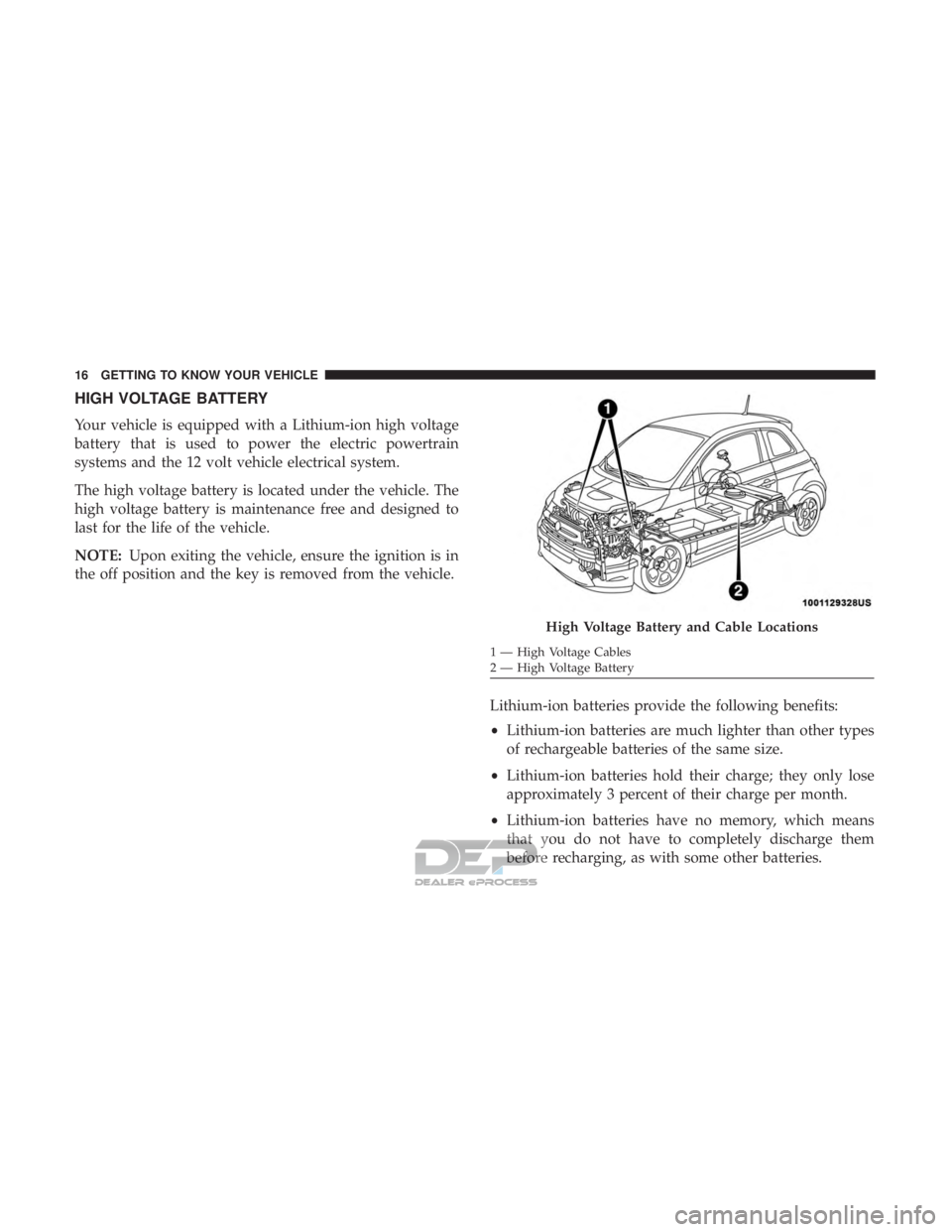
Your vehicle is equipped with a Lithium-ion high voltage
battery that is used to power the electric powertrain
systems and the 12 volt vehicle electrical system.
The high voltage battery is located under the vehicle. The
high voltage battery is maintenance free and designed to
last for the life of the vehicle.
NOTE:Upon exiting the vehicle, ensure the ignition is in
the off position and the key is removed from the vehicle.
Lithium-ion batteries provide the following benefits:
•Lithium-ion batteries are much lighter than other types
of rechargeable batteries of the same size.
• Lithium-ion batteries hold their charge; they only lose
approximately 3 percent of their charge per month.
• Lithium-ion batteries have no memory, which means
that you do not have to completely discharge them
before recharging, as with some other batteries.
High Voltage Battery and Cable Locations
1 — High Voltage Cables
2 — High Voltage Battery
16 GETTING TO KNOW YOUR VEHICLE
Page 20 of 302
500e ELECTRIC VEHICLE FEATURES
Understanding the unique characteristics of your 500e will
help ensure maximum performance and the best driving
range from your vehicle.
Your 500e is equipped with two electrical systems; a 12 Volt
system that is used to power the conventional electrical
system and a high voltage system, which is used to drive
the wheels through a single-speed transmission as well as
other high voltage system components.
Your 500e operates differently then a traditional vehicle or
Hybrid vehicle. Here are some of the main differences:
Audible Pedestrian Warning System
Your vehicle is equipped with an Audible Pedestrian
Warning System. The Audible Pedestrian Warning System
uses distinct sounds to alert pedestrians that your vehicle is
approaching.
The audible warning system uses an in-car sound synthe-
sizer with a speaker located in the underhood compart-
ment. The warning system is automatically activated when
selecting DRIVE or REVERSE.
In DRIVE range, the system will remain active until the
vehicle reaches a speed of approximately 22 mph(35.5 km/h). At approximately 22 mph (35.5 km/h), the
warning system is deactivated and will automatically be
active when the vehicle returns to approximately 20 mph
(32 km/h).
Single-Speed Transmission
Instead of a traditional transmission, your vehicle is
equipped with a single-speed transmission to transfer the
torque from the E-Drive motor to the drive wheels. This
transmission requires no maintenance and is designed to
operate for the life of the vehicle.
Auto Park
Auto Park will automatically place the transmission into
PARK if there is an indication that the driver may leave the
vehicle while still in the DRIVE, NEUTRAL or REVERSE
gear. Refer to “Single-Speed Transmission” in “Starting
And Operating” in your Owner ’s Manual for further
information.
E-Park
The parking pawl is traditionally located inside an auto-
matic transmission and activated when the vehicle is
placed in the PARK position.
18 GETTING TO KNOW YOUR VEHICLE
Page 21 of 302
E-Park is activated when the driver pushes the PARK
button. An electric motor activates the parking pawl and
locks the single-speed transmission when the vehicle is
placed into PARK. This will prevent any unwanted move-
ment of the vehicle.
NOTE:The engagement of the E-Park can be heard when
there is no noise in the interior of the vehicle, this is a
normal condition.
Climate Control (HVAC System)
Your 500e is equipped with an Automatic Temperature
Control (ATC) HVAC system. This HVAC system utilizes a
humidity sensor, cabin sensor, and ambient temperature
sensor to choose operation mode and control cabin com-
fort. These components allow the controller to operate the
HVAC system in a very efficient manner to maximize
driving range.
Your 500e also uses an electric air heater to provide heat to
the cabin.
Electric Air Conditioning Compressor
Your 500e uses an electric air conditioning compressor. The
air conditioning compressor is powered by the high volt-
age battery system and is used to cool the vehicle occu-
pants and the high voltage battery while the vehicle is
being driven or when it is being charged.
The high voltage battery may require cooling to keep the
vehicle running. The air conditioning compressor activates
without any input from the occupant.
NOTE: The AC system helps cool the high voltage battery.
If the air conditioning system should require service, see an
authorized dealer as soon as possible.
Electric Power Steering
Your vehicle is equipped with an Electric Power Steering
(EPS) system. The power steering system requires no
maintenance and operates without the use of power steer-
ing fluid.
3
GETTING TO KNOW YOUR VEHICLE 19
Page 97 of 302

CAUTION!
Do not continue driving with one or more flat tires as
handling may be compromised. Stop the vehicle,
avoiding sharp braking and steering. If a tire puncture
occurs, repair immediately using the dedicated tire
repair kit and contact an authorized dealer as soon as
possible.
Each tire, including the spare (if provided), should be
checked monthly when cold and inflated to the inflation
pressure recommended by the vehicle manufacturer on the
vehicle placard or tire inflation pressure label. (If your
vehicle has tires of a different size than the size indicated
on the vehicle placard or tire inflation pressure label, you
should determine the proper tire inflation pressure for
those tires.)
As an added safety feature, your vehicle has been
equipped with a Tire Pressure Monitoring System (TPMS)
that illuminates a low tire pressure telltale when one or
more of your tires is significantly under-inflated. Accord-
ingly, when the low tire pressure telltale illuminates, you
should stop and check your tires as soon as possible, and
inflate them to the proper pressure. Driving on a signifi-
cantly under-inflated tire causes the tire to overheat and can lead to tire failure. Under-inflation also reduces fuel
efficiency and tire tread life, and may affect the vehicle’s
handling and stopping ability.
Please note that the TPMS is not a substitute for proper tire
maintenance, and it is the driver ’s responsibility to main-
tain correct tire pressure, even if under-inflation has not
reached the level to trigger illumination of the TPMS low
tire pressure telltale.
Your vehicle has also been equipped with a TPMS malfunc-
tion indicator to indicate when the system is not operating
properly. The TPMS malfunction indicator is combined
with the low tire pressure telltale. When the system detects
a malfunction, the telltale will flash for approximately one
minute and then remain continuously illuminated. This
sequence will continue upon subsequent vehicle start-ups
as long as the malfunction exists. When the malfunction
indicator is illuminated, the system may not be able to
detect or signal low tire pressure as intended. TPMS
malfunctions may occur for a variety of reasons, including
the installation of replacement or alternate tires or wheels
on the vehicle that prevent the TPMS from functioning
properly. Always check the TPMS malfunction telltale after
replacing one or more tires or wheels on your vehicle to
ensure that the replacement or alternate tires and wheels
allow the TPMS to continue to function properly.
4
GETTING TO KNOW YOUR INSTRUMENT PANEL 95
Page 105 of 302
WARNING!(Continued)
the performance of the ESC system. Changes to the
steering system, suspension, braking system, tire
type and size or wheel size may adversely affect ESC
performance. Improperly inflated and unevenly
worn tires may also degrade ESC performance. Any
vehicle modification or poor vehicle maintenance
that reduces the effectiveness of the ESC system can
increase the risk of loss of vehicle control, vehicle
rollover, personal injury and death.
ESC Operating Modes
The ESC system has two available operating modes.
Full On
This is the normal operating mode for ESC. Whenever the
vehicle is started, the ESC system will be in On mode. This
mode should be used for most driving situations. ESC
should only be turned to Partial Off for specific reasons as
noted below.
Partial Off
This mode is entered by momentarily pushing the ESC Off
switch. This mode is intended to be used if the vehicle is in deep snow, sand or gravel conditions and more wheel spin
than ESC would normally allow is required to gain trac-
tion.
To turn ESC on again, momentarily pushing the switch
again. This will restore the normal ESC On mode of
operation.
NOTE:
To improve the vehicle’s traction when driving
with snow chains, or starting off in deep snow, sand or
gravel, it may be desirable to switch to the Partial Off mode
by pushing the switch. Once the situation requiring ESC to
be switched to the Partial Off mode is overcome, turn ESC
back on by momentarily pushing the switch. This may be
done while the vehicle is in motion.
WARNING!
When in “Partial Off” mode, the TCS functionality of
ESC, (except for the limited slip feature described in
the TCS section), has been disabled and the “ESC Off
Indicator Light” will be illuminated. When in “Partial
Off” mode, the motor power reduction feature of TCS
is disabled, and the enhanced vehicle stability offered
by the ESC system is reduced.
5
SAFETY 103
Page 107 of 302
The RBS uses conventional hydraulic friction brakes, re-
generative braking, or a combination to slow the vehicle. If
the system detects slippery conditions while braking,
ONLY friction is used to slow the vehicle. The RBS can
result in extended life of the hydraulic service brakes;
however, all inspection, scheduled maintenance, and ser-
vice intervals for the vehicle service brakes must be fol-
lowed.
AUXILIARY DRIVING SYSTEMS
Tire Pressure Monitor System
The Tire Pressure Monitor System (TPMS) will warn the
driver of a low tire pressure based on the vehicle recom-
mended cold placard pressure.
The tire pressure will vary with temperature by about 1psi
(7 kPa) for every 12°F (6.5°C). This means that when the
outside temperature decreases, the tire pressure will de-
crease. Tire pressure should always be set based on cold
inflation tire pressure. This is defined as the tire pressure
after the vehicle has not been driven for at least three
hours, or driven less than 1 mile (1.6 km) after a three hour
period. The cold tire inflation pressure must not exceed the
maximum inflation pressure molded into the tire sidewall.
Refer to “Tires – General Information” in “Servicing AndMaintenance” for information on how to properly inflate
the vehicle’s tires. The tire pressure will also increase as the
vehicle is driven. This is normal and there should be no
adjustment for this increased pressure.
The TPMS will warn the driver of a low tire pressure if the
tire pressure falls below the low-pressure warning limit for
any reason, including low temperature effects and natural
pressure loss through the tire.
The TPMS will continue to warn the driver of low tire
pressure as long as the condition exists, and will not turn
off until the tire pressure is at or above the recommended
cold placard pressure. Once the low tire pressure warning
(Tire Pressure Monitoring System Warning Light) illumi-
nates, you must increase the tire pressure to the recom-
mended cold placard pressure in order for the Tire Pressure
Monitoring System Warning Light to turn off. The system
will automatically update and the Tire Pressure Monitoring
System Warning Light will turn off once the system re-
ceives the updated tire pressures. The vehicle may need to
be driven for up to 20 minutes above 15 mph (24 km/h) in
order for the TPMS to receive this information.
For example, your vehicle may have a recommended cold
(parked for more than three hours) placard pressure of
33 psi (227 kPa). If the ambient temperature is 68°F (20°C)
5
SAFETY 105
Page 108 of 302
and the measured tire pressure is 28 psi (193 kPa), a
temperature drop to 20°F (-7°C) will decrease the tire
pressure to approximately 24 psi (165 kPa). This tire
pressure is low enough to turn ON the “Tire Pressure
Monitoring System Warning Light.” Driving the vehicle
may cause the tire pressure to rise to approximately 28 psi
(193 kPa), but the Tire Pressure Monitoring System Warn-
ing Light will still be on. In this situation, the Tire Pressure
Monitoring System Warning Light will turn off only after
the tires are inflated to the vehicle’s recommended cold
placard pressure value.
CAUTION!
•The TPMS has been optimized for the original
equipment tires and wheels. TPMS pressures and
warnings have been established for the tire size
equipped on your vehicle. Undesirable system op-
eration or sensor damage may result when using
replacement equipment that is not of the same size,
type, and/or style. The TPM sensor is not designed
for use on aftermarket wheels and may contribute to
a poor overall system performance or sensor damage.
(Continued)
CAUTION! (Continued)
Customers are encouraged to use OEM wheels to
assure proper TPM feature operation.
• Using aftermarket tire sealants may cause the Tire
Pressure Monitoring System (TPMS) sensor to be-
come inoperable. After using an aftermarket tire
sealant it is recommended that you take your vehicle
to an authorized dealership to have your sensor
function checked.
• After inspecting or adjusting the tire pressure, al-
ways reinstall the valve stem cap. This will prevent
moisture and dirt from entering the valve stem,
which could damage the Tire Pressure Monitoring
Sensor.
NOTE:
• The TPMS is not intended to replace normal tire care and
maintenance, or to provide warning of a tire failure or
condition.
• The TPMS should not be used as a tire pressure gauge
while adjusting your tire pressure.
• Driving on a significantly under-inflated tire causes the
tire to overheat and can lead to tire failure.
106 SAFETY
Page 123 of 302
•Instrument Panel
• Knee Impact Bolsters
• Driver and Front Passenger Air Bags
• Seat Belt Buckle Switch
• Supplemental Side Air Bags
• Supplemental Knee Air Bags
• Front and Side Impact Sensors
• Seat Belt Pretensioners
• Seat Track Position Sensors
Air Bag Warning Light
The ORC monitors the readiness of the electronic
parts of the air bag system whenever the ignition
switch is in the AVV/START or MAR/ACC/
ON/RUN position. If the ignition switch is in the
STOP/OFF/LOCK position the air bag system is not on
and the air bags will not inflate.
The ORC contains a backup power supply system that may
deploy the air bag system even if the battery loses power or
it becomes disconnected prior to deployment. The ORC turns on the Air Bag Warning Light in the
instrument panel for approximately four to eight seconds
for a self-check when the ignition switch is in the MAR/
ACC/ON/RUN position. After the self-check, the Air Bag
Warning Light will turn off. If the ORC detects a malfunc-
tion in any part of the system, it turns on the Air Bag
Warning Light, either momentarily or continuously. A
single chime will sound to alert you if the light comes on
again after initial startup.
The ORC also includes diagnostics that will illuminate the
instrument panel Air Bag Warning Light if a malfunction is
detected that could affect the air bag system. The diagnos-
tics also record the nature of the malfunction. While the air
bag system is designed to be maintenance free, if any of the
following occurs, have an authorized dealer service the air
bag system immediately.
•
The Air Bag Warning Light does not come on during the
four to eight seconds when the ignition switch is first in
the MAR/ACC/ON/RUN position.
• The Air Bag Warning Light remains on after the four to
eight-second interval.
• The Air Bag Warning Light comes on intermittently or
remains on while driving.
5
SAFETY 121