sensor FIAT 500L 2015 2.G User Guide
[x] Cancel search | Manufacturer: FIAT, Model Year: 2015, Model line: 500L, Model: FIAT 500L 2015 2.GPages: 438, PDF Size: 12.64 MB
Page 135 of 438
•Objects such as bicycle carriers, etc., must not be
placed within 12 in (30 cm) from the rear fascia/
bumper while driving the vehicle. Failure to do so can
result in the system misinterpreting a close object as a
sensor problem, causing a failure indication to be
displayed in the instrument cluster.
CAUTION!
•Rear Park Assist is only a parking aid and it is
unable to recognize every obstacle, including small
obstacles. Parking curbs might be temporarily de-
tected or not detected at all. Obstacles located
above or below the sensors will not be detected
when they are in close proximity.
(Continued)
CAUTION!(Continued)
•The vehicle must be driven slowly when using
Rear Park Assist in order to be able to stop in time
when an obstacle is detected. It is recommended
that the driver looks over his/her shoulder when
using Rear Park Assist.
WARNING!
•Drivers must be careful when backing up even
when using ParkSense®. Always check carefully
behind your vehicle, look behind you, and be sure
to check for pedestrians, animals, other vehicles,
obstructions, and blind spots before backing up.
You are responsible for safety and must continue to
pay attention to your surroundings. Failure to do so
can result in serious injury or death.
(Continued)
3
UNDERSTANDING THE FEATURES OF YOUR VEHICLE 133
Page 136 of 438
WARNING!(Continued)
•Before using ParkSense®, it is strongly recom-
mended that the ball mount and hitch ball assem-
bly is disconnected from the vehicle when the
vehicle is not used for towing. Failure to do so can
result in injury or damage to vehicles or obstacles
because the hitch ball will be much closer to the
obstacle than the rear fascia when the loudspeaker
sounds the continuous tone. Also, the sensors
could detect the ball mount and hitch ball assem-
bly, depending on its size and shape, giving a false
indication that an obstacle is behind the vehicle.
If it’s necessary to keep the ball mount and hitch ball
assembly mounted for a long period, it is possible to filter
out the ball mount and hitch ball assembly presence in
sensor field of view. The filtering operation must be
performed only by an authorized dealer.
PARKVIEW® REAR BACK UP CAMERA — IF
EQUIPPED
Your vehicle may be equipped with the ParkView® Rear
Back Up Camera that allows you to see an on-screen
image of the rear surroundings of your vehicle whenever
the shift lever is put into REVERSE. The image will be
displayed in the touchscreen display along with a caution
note to “check entire surroundings” across the top of the
screen. After five seconds this note will disappear. The
ParkView® camera is located on the rear of the vehicle
above the rear License plate.
When the vehicle is shifted out of REVERSE, the rear
camera mode is exited and the last selected touchscreen
appears again.
If your vehicle is equipped with the Camera Delay
feature and it is turned On, the rear camera image will be
displayed for up to 10 seconds when the vehicle is shifted
134 UNDERSTANDING THE FEATURES OF YOUR VEHICLE
Page 177 of 438
CAUTION!
The TPMS has been optimized for the original
equipment tires and wheels. TPMS pressures and
warning have been established for the tire size
equipped on your vehicle. Undesirable system opera-
tion or sensor damage may result when using re-
placement equipment that is not of the same size,
type, and/or style. Aftermarket wheels can cause
sensor damage. Using aftermarket tire sealants may
cause the Tire Pressure Monitoring System (TPMS)
sensor to become inoperable. After using an after-
market tire sealant it is recommended that you take
your vehicle to an authorized dealership to have your
sensor function checked.
21. Glow Plug Light — If Equipped
This vehicle will inhibit engine cranking when the
ambient temperature is less than –22° F (–30° C)
and the oil temperature sensor reading indicates an
engine block heater has not been used. The Glow Plug
light will flash during in cold weather for up to 10
seconds.
If equipped with a block heater harness the message
#Plug In Engine Heater#, will be displayed in the instru-
ment cluster when the ambient temperature is below 5°F
(-15° C) at the time the engine is shut off as a reminder to
avoid possible crank delays at the next cold start.
22. Odometer / Trip Odometer / Electronic Vehicle Infor-
mation Center (EVIC) Display Area
This display indicates the total distance the vehicle has
been driven.
4
UNDERSTANDING YOUR INSTRUMENT PANEL 175
Page 203 of 438
•air distribution to seven positions;
•compressor enablement;
•rapid defrosting/demisting function;
•air recirculation;
•heated rear window;
•system deactivation.
NOTE:The climate control system detects the passenger
compartment temperature using a mean radiant tem-
perature sensor located in the interior rear view mirror
and protected by a specific cover. Obstructing the field of
view of this sensor with any object could cause the
climate control system to operate with less than optimal
efficiency.
Switching On The Climate Control System
The climate control system can be switched on in differ-
ent ways: it is advisable to push the AUTO button and
turn the knobs to set the desired temperatures.
In this way the system operates completely automatically
to adjust the temperature, quantity and distribution of
the air introduced into the passenger compartment. It
also manages the air recirculation function and the acti-
vation of the air conditioning compressor.
During automatic operation, you can change the set
temperatures, air distribution and fan speed at any time
by using the relevant buttons or knobs: the system will
automatically change the settings to adjust to the new
requirements.
4
UNDERSTANDING YOUR INSTRUMENT PANEL 201
Page 227 of 438
Turn the ignition switch to the AVV/ACC (START)
position and release it when the engine starts. If the
engine fails to start within 10 seconds, turn the ignition
switch to the STOP (OFF/LOCK) position, wait 10 to 15
seconds, then repeat the “Normal Starting” procedure.
Cold Weather Operation
To prevent possible engine damage while starting at low
temperatures, this vehicle will inhibit engine cranking
when the ambient temperature is less than –22° F (–30° C)
and the oil temperature sensor reading indicates an
engine block heater has not been used. An externally
powered electric engine block heater is available as a
factory installed option.
The message “plug in engine heater” will be displayed in
the instrument cluster when the ambient temperature is
below 5° F (–15° C) at the time the engine is shut off as a
reminder to avoid possible crank delays at the next cold
start.
NOTE:Use of the recommended SAE 5W-40 Synthetic oil
and adhering to the prescribed oil change intervals is
important to prevent engine damage and ensure satisfac-
tory starting in cold conditions.
Extended Park Starting
NOTE:Extended Park condition occurs when the vehicle
has not been started or driven for at least 35 days.
1. Install a battery charger or jumper cables to the battery
to ensure a full battery charge during the crank cycle.
2. Cycle the ignition in the START position and release it
when the engine starts.
3. If the engine fails to start within ten seconds, cycle the
ignition to the STOP (OFF/LOCK) position, wait five
seconds to allow the starter to cool, then repeat the
Extended Park Starting procedure.
5
STARTING AND OPERATING 225
Page 243 of 438
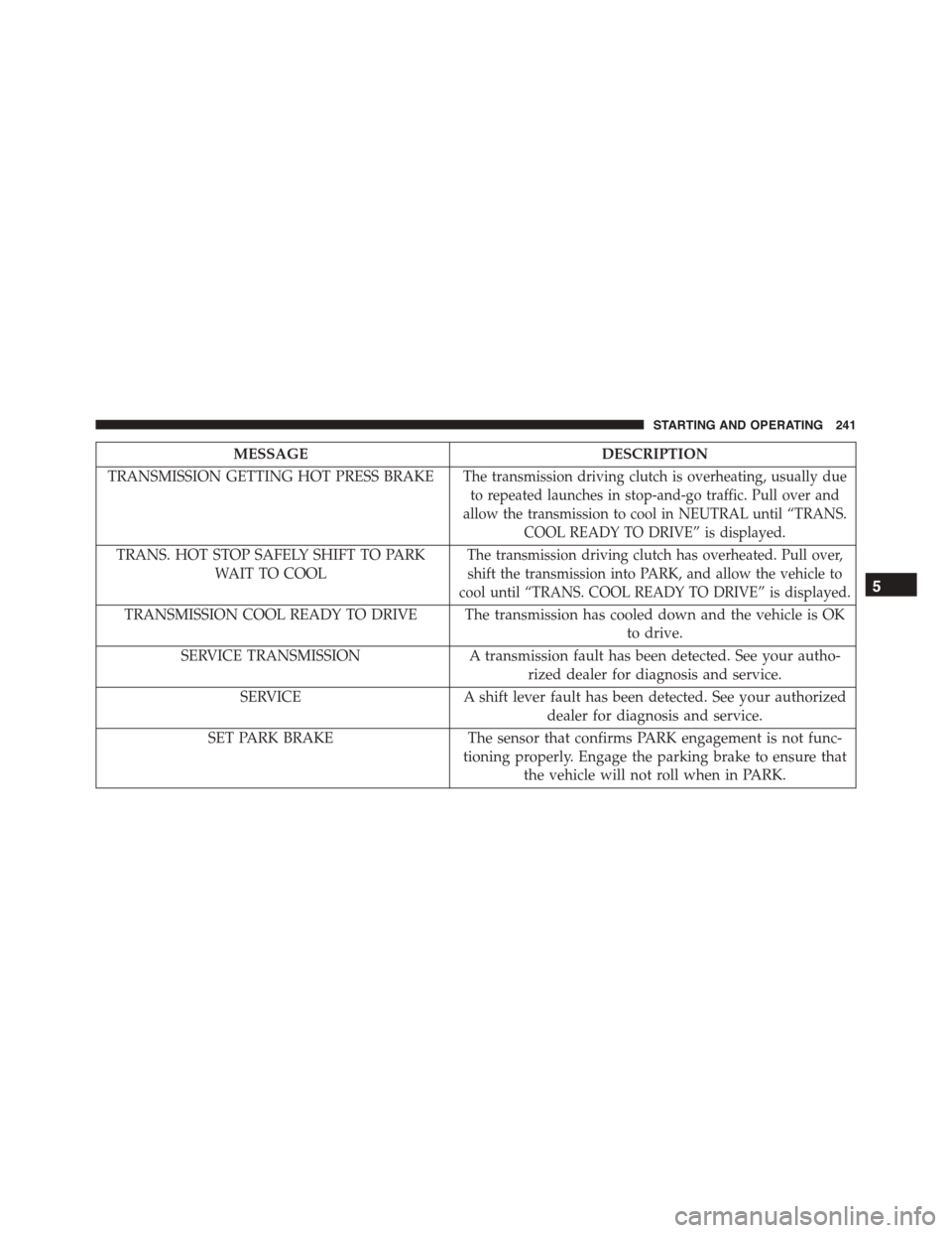
MESSAGEDESCRIPTION
TRANSMISSION GETTING HOT PRESS BRAKEThe transmission driving clutch is overheating, usually due
to repeated launches in stop-and-go traffic. Pull over and
allow the transmission to cool in NEUTRAL until “TRANS.
COOL READY TO DRIVE” is displayed.
TRANS. HOT STOP SAFELY SHIFT TO PARK
WAIT TO COOL
The transmission driving clutch has overheated. Pull over,
shift the transmission into PARK, and allow the vehicle to
cool until “TRANS. COOL READY TO DRIVE” is displayed.
TRANSMISSION COOL READY TO DRIVE The transmission has cooled down and the vehicle is OK
to drive.
SERVICE TRANSMISSIONA transmission fault has been detected. See your autho-
rized dealer for diagnosis and service.
SERVICEA shift lever fault has been detected. See your authorized
dealer for diagnosis and service.
SET PARK BRAKEThe sensor that confirms PARK engagement is not func-
tioning properly. Engage the parking brake to ensure that
the vehicle will not roll when in PARK.
5
STARTING AND OPERATING 241
Page 264 of 438
Electronic Stability Control (ESC)
This system enhances directional control and stability of
the vehicle under various driving conditions. ESC cor-
rects for oversteering or understeering of the vehicle by
applying the brake of the appropriate wheel to assist in
counteracting the oversteering or understeering condi-
tion. Engine power may also be reduced to help the
vehicle maintain the desired path. ESC uses sensors in
the vehicle to determine the vehicle path intended by the
driver and compares it to the actual path of the vehicle.
When the actual path does not match the intended path,
ESC applies the brake of the appropriate wheel to assist
in counteracting the oversteer or understeer condition.
•Oversteer - when the vehicle is turning more than
appropriate for the steering wheel position.
•Understeer - when the vehicle is turning less than
appropriate for the steering wheel position.
WARNING!
The Electronic Stability Control (ESC) cannot pre-
vent the natural laws of physics from acting on the
vehicle, nor can it increase the traction afforded by
prevailing road conditions. ESC cannot prevent all
accidents, including those resulting from excessive
speed in turns, driving on very slippery surfaces, or
hydroplaning. ESC also cannot prevent collisions
resulting from loss of vehicle control due to inappro-
priate driver input for the conditions. Only a safe,
attentive, and skillful driver can prevent accidents.
The capabilities of an ESC equipped vehicle must
never be exploited in a reckless or dangerous manner
which could jeopardize the user ’s safety or the safety
of others.
262 STARTING AND OPERATING
Page 297 of 438
CAUTION!
•The TPMS has been optimized for the original
equipment tires and wheels. TPMS pressures and
warnings have been established for the tire size
equipped on your vehicle. Undesirable system op-
eration or sensor damage may result when using
replacement equipment that is not of the same size,
type, and/or style. Aftermarket wheels can cause
sensor damage. Using aftermarket tire sealants may
cause the Tire Pressure Monitoring System (TPMS)
sensor to become inoperable. After using an after-
market tire sealant it is recommended that you take
your vehicle to your an authorized dealership to
have your sensor function checked.
(Continued)
CAUTION!(Continued)
•After inspecting or adjusting the tire pressure,
always reinstall the valve stem cap. This will
prevent moisture and dirt from entering the valve
stem, which could damage the Tire Pressure Moni-
toring Sensor.
NOTE:
•The TPMS is not intended to replace normal tire care
and maintenance, or to provide warning of a tire
failure or condition.
•The TPMS should not be used as a tire pressure gauge
while adjusting your tire pressure.
•Driving on a significantly under-inflated tire causes
the tire to overheat and can lead to tire failure.
5
STARTING AND OPERATING 295
Page 298 of 438

Under-inflation also reduces fuel efficiency and tire
tread life, and may affect the vehicle’s handling and
stopping ability.
•The TPMS is not a substitute for proper tire mainte-
nance, and it is the driver ’s responsibility to maintain
correct tire pressure using an accurate tire gauge, even
if under-inflation has not reached the level to trigger
illumination of the Tire Pressure Monitoring Telltale
Light.
•Seasonal temperature changes will affect tire pressure,
and the TPMS will monitor the actual tire pressure in
the tire.
Base System
This is the TPMS warning indicator located in the
instrument cluster.
The TPMS uses wireless technology with wheel rim
mounted electronic sensors to monitor tire pressure lev-
els. Sensors, mounted to each wheel as part of the valve
stem, transmit tire pressure readings to the Receiver
Module.
NOTE:It is particularly important for you to check the
tire pressure in all of the tires on your vehicle regularly
and to maintain the proper pressure.
The TPMS consists of the following components:
•Receiver Module.
•Four Tire Pressure Monitoring Sensors.
•Tire Pressure Monitoring Telltale Light.
Tire Pressure Monitoring Low Pressure Warnings
The Tire Pressure Monitoring Telltale Light will illumi-
nate in the instrument cluster, an audible chime will be
activated, and the “Check left or right front/rear tire”
296 STARTING AND OPERATING
Page 299 of 438
text message will display when one or more of the four
active road tire pressures are low. Should this occur, you
should stop as soon as possible, check the inflation
pressure of each tire on your vehicle, and inflate each tire
to the vehicle’s recommended cold placard pressure
value. The system will automatically update and the Tire
Pressure Monitoring Light will extinguish once the up-
dated tire pressures have been received. The vehicle may
need to be driven for up to 20 minutes above 15 mph
(24 km/h) to receive this information.
Check TPMS Warnings
The Tire Pressure Monitoring Telltale Light will flash on
and off for 75 seconds and remain on solid when a system
fault is detected, an audible chime will be activated and
the “Service Tire Pressure Monitoring System” text mes-
sage will display. If the ignition key is cycled, this
sequence will repeat providing the system fault still
exists. The Tire Pressure Monitoring Telltale Light will
turn off when the fault condition no longer exists. A
system fault can occur with any of the following sce-
narios:
1. Jamming due to electronic devices or driving next to
facilities emitting the same radio frequencies as the
TPM sensors.
2. Installing some form of aftermarket window tinting
that affects radio wave signals.
3. Snow or ice around the wheels or wheel housings.
4. Using tire chains on the vehicle.
5. Using wheels/tires not equipped with TPM sensors.
NOTE:Your vehicle may be equipped with a compact
spare wheel and tire assembly.
1. The compact spare tire does not have a tire pressure
monitoring sensor. Therefore, the TPMS will not moni-
tor the tire pressure in the compact spare tire.
5
STARTING AND OPERATING 297