door lock FIAT 500L 2015 2.G User Guide
[x] Cancel search | Manufacturer: FIAT, Model Year: 2015, Model line: 500L, Model: FIAT 500L 2015 2.GPages: 148, PDF Size: 3.77 MB
Page 3 of 148
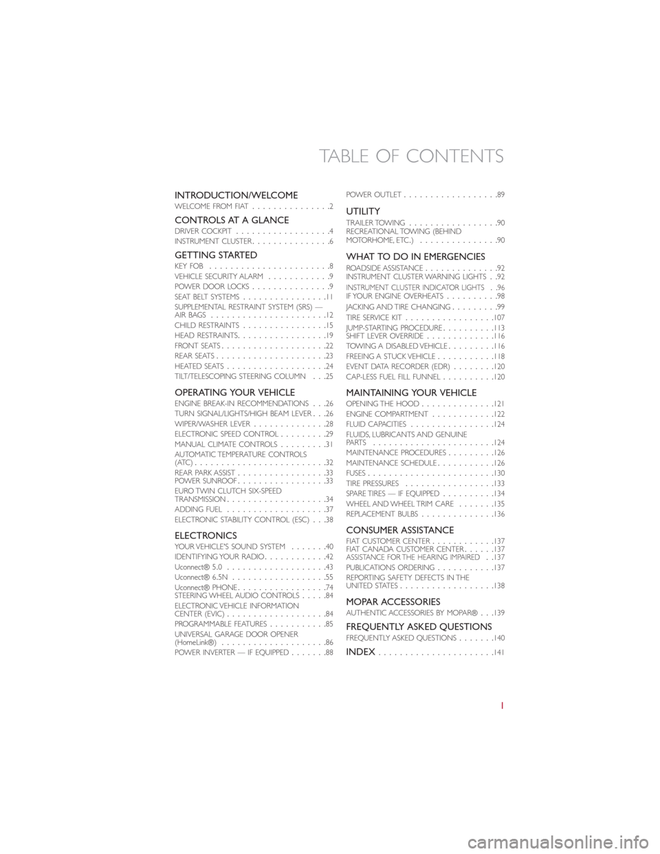
INTRODUCTION/WELCOMEWELCOME FROM FIAT...............2
CONTROLS AT A GLANCEDRIVER COCKPIT..................4INSTRUMENT CLUSTER...............6
GETTING STARTEDKEY FOB.......................8VEHICLE SECURITY ALARM............9POWER DOOR LOCKS...............9SEAT BELT SYSTEMS................11SUPPLEMENTAL RESTRAINT SYSTEM (SRS) —AIR BAGS......................12CHILD RESTRAINTS................15HEAD RESTRAINTS.................19FRONT SEATS....................22REAR SEATS.....................23HEATED SEATS...................24TILT/TELESCOPING STEERING COLUMN...25
OPERATING YOUR VEHICLEENGINE BREAK-IN RECOMMENDATIONS...26TURN SIGNAL/LIGHTS/HIGH BEAM LEVER...26WIPER/WASHER LEVER..............28ELECTRONIC SPEED CONTROL.........29MANUAL CLIMATE CONTROLS.........31AUTOMATIC TEMPERATURE CONTROLS(ATC).........................32REAR PARK ASSIST.................33POWER SUNROOF.................33EURO TWIN CLUTCH SIX-SPEEDTRANSMISSION...................34ADDING FUEL...................37ELECTRONIC STABILITY CONTROL (ESC)...38
ELECTRONICSYO U R V E H I C L E ' S S O U N D S YS T E M.......40IDENTIFYING YOUR RADIO............42Uconnect® 5.0...................43Uconnect® 6.5N..................55Uconnect® PHONE.................74STEERING WHEEL AUDIO CONTROLS.....84ELECTRONIC VEHICLE INFORMATIONCENTER (EVIC)...................84PROGRAMMABLE FEATURES...........85UNIVERSAL GARAGE DOOR OPENER(HomeLink®)....................86POWER INVERTER — IF EQUIPPED.......88
POWER OUTLET..................89
UTILITY
TRAILER TOWING.................90RECREATIONAL TOWING (BEHINDMOTORHOME, ETC.)...............90
WHAT TO DO IN EMERGENCIES
ROADSIDE ASSISTANCE..............92INSTRUMENT CLUSTER WARNING LIGHTS..92INSTRUMENT CLUSTER INDICATOR LIGHTS..96IF YOUR ENGINE OVERHEATS..........98JACKING AND TIRE CHANGING.........99TIRE SERVICE KIT.................107JUMP-STARTING PROCEDURE..........113SHIFT LEVER OVERRIDE.............116TOW I N G A D I S A B L E D V E H I C L E.........116FREEING A STUCK VEHICLE...........118EVENT DATA RECORDER (EDR)........120CAP-LESS FUEL FILL FUNNEL..........120
MAINTAINING YOUR VEHICLEOPENING THE HOOD..............121ENGINE COMPARTMENT............122FLUID CAPACITIES................124FLUIDS, LUBRICANTS AND GENUINEPA RT S.......................124MAINTENANCE PROCEDURES.........126MAINTENANCE SCHEDULE...........126FUSES........................130TIRE PRESSURES.................133SPARE TIRES — IF EQUIPPED..........134WHEEL AND WHEEL TRIM CARE.......135REPLACEMENT BULBS..............136
CONSUMER ASSISTANCEFIAT CUSTOMER CENTER............137FIAT CANADA CUSTOMER CENTER......137ASSISTANCE FOR THE HEARING IMPAIRED..137PUBLICATIONS ORDERING...........137REPORTING SAFETY DEFECTS IN THEUNITED STATES..................138
MOPAR ACCESSORIESAUTHENTIC ACCESSORIES BY MOPAR®...139
FREQUENTLY ASKED QUESTIONSFREQUENTLY ASKED QUESTIONS.......140
INDEX......................141
TABLE OF CONTENTS
1
Page 6 of 148
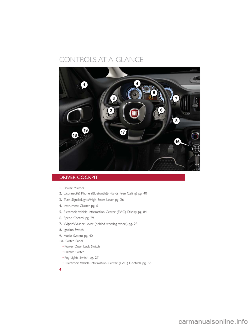
DRIVER COCKPIT
1.Power Mirrors
2.Uconnect® Phone (Bluetooth® Hands Free Calling) pg.40
3.Turn Signals/Lights/High Beam Lever pg.26
4.Instrument Cluster pg.6
5.Electronic Vehicle Information Center (EVIC) Display pg.84
6.Speed Control pg.29
7.Wiper/Washer Lever (behind steering wheel) pg.28
8.Ignition Switch
9.Audio System pg.40
10.Switch Panel
•Power Door Lock Switch
•Hazard Switch
•Fog Lights Switch pg.27
•Electronic Vehicle Information Center (EVIC) Controls pg.85
CONTROLS AT A GLANCE
4
Page 10 of 148
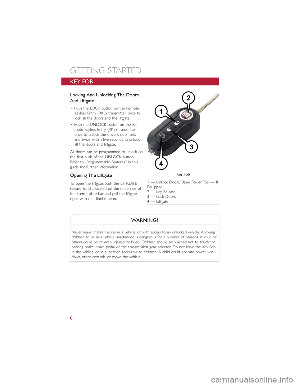
KEY FOB
Locking And Unlocking The Doors
And Liftgate
•Push the LOCK button on the Remote
Keyless Entry (RKE) transmitter once to
lock all the doors and the liftgate.
•Push the UNLOCK button on the Re-
mote Keyless Entry (RKE) transmitter
once to unlock the driver’s door only
and twice within five seconds to unlock
all the doors and liftgate.
All doors can be programmed to unlock on
the first push of the UNLOCK button.
Refer to “Programmable Features” in this
guide for further information.
Opening The Liftgate
To open the liftgate, push the LIFTGATE
release handle located on the underside of
the license plate bar and pull the liftgate
open with one fluid motion.
WARNING!
Never leave children alone in a vehicle, or with access to an unlocked vehicle.Allowing
children to be in a vehicle unattended is dangerous for a number of reasons.A child or
others could be severely injured or killed.Children should be warned not to touch the
parking brake, brake pedal, or the transmission gear selector.Do not leave the Key Fob
in the vehicle, or in a location accessible to children.A child could operate power win-
dows, other controls, or move the vehicle.
Key Fob
1 — Unlock Doors/Open Power Top — IfEquipped2 — Key Release3 — Lock Doors4 — Liftgate
GETTING STARTED
8
Page 11 of 148
VEHICLE SECURITY ALARM
The Vehicle Security Alarm monitors the vehicle doors for unauthorized entry and the
Keyless Enter-N-Go™ START/STOP button for unauthorized operation.While the Vehicle
Security Alarm is armed, interior switches for door locks and decklid release are disabled.
If something triggers the alarm, the Vehicle Security Alarm will provide the following au-
dible and visible signals: the horn will pulse, the park lamps and/or turn signals will flash,
and the Vehicle Security Light in the instrument cluster will flash.
To Arm The System:
Push the Key Fob LOCK button.
To Disarm The System:
Push the Key Fob UNLOCK button or cycle the ignition to the ON/RUN position.
The Vehicle Security Alarm is designed to protect your vehicle.However, you can create
conditions where the Vehicle Security Alarm will give you a false alarm.If one of the pre-
viously described arming sequences has occurred, the Vehicle Security Alarm will arm re-
gardless of whether you are in the vehicle or not.If you remain in the vehicle and open
a door, the alarm will sound.If this occurs, disarm the Vehicle Security Alarm.
If the Vehicle Security Alarm is armed and the battery becomes disconnected, the Vehicle
Security Alarm will remain armed when the battery is reconnected.The exterior lights
will flash, and the horn will sound.If this occurs, disarm the Vehicle Security Alarm.
POWER DOOR LOCKS
•Push the central LOCK/UNLOCK button located on the instrument panel, in the
switch bank below the radio.The button has an LED that indicates whether the doors
are locked or unlocked.
•LED ON:doors locked.Pushing the central LOCK/UNLOCK button once will unlock
all doors.The LED will switch off once the doors are unlocked.
•LED OFF:doors unlocked.Pushing the central LOCK/UNLOCK button once will lock
all doors.The LED will switch on once the doors are locked.
•Once the doors have been locked with the RKE transmitter, it will no longer be pos-
sible to unlock them by pushing central LOCK/UNLOCK button.
NOTE:
With central locking active (LED ON), opening one of the front doors, it is possible to
perform a central unlocking (LED OFF).With central locking active (LED ON), in order
to open one of the rear passenger doors, it is necessary pulling the internal door handle
twice.With one of the rear door open (LED OFF), the unlocking is performed only for
that door, not for all the vehicle.
•To unlock the front doors, pull the inside door handle to the first detent.If the rear
doors are locked, you must pull the door handle once to unlock the door and pull the
door handle a second time to open the door.
GETTING STARTED
9
Page 12 of 148
CAUTION!
An unlocked vehicle is an invitation to thieves.Always remove the key from the ignition
and lock all of the doors when leaving the vehicle unattended.
WARNING!
•Do not leave children or animals inside parked vehicles in hot weather.Interior
heat build-up may cause serious injury or death.
•For personal security and safety in the event of an collision, lock the vehicle doors
as you drive as well as when you park and leave the vehicle.
•Before exiting a vehicle, always turn the vehicle OFF, apply the parking brake, shift
the Euro Twin Clutch transmission into PARK or the manual transmission into RE-
VERSE, and remove the Key Fob from the ignition.When leaving the vehicle, al-
ways lock your vehicle.
•Never leave children alone in a vehicle, or with access to an unlocked vehicle.
•Allowing children to be in a vehicle unattended is dangerous for a number of rea-
sons.A child or others could be seriously or fatally injured.Children should be
warned not to touch the parking brake, brake pedal or the transmission gear se-
lector.
•Do not leave the Key Fob in or near the vehicle, or in a location accessible to
child.A child could operate power windows, other controls, or move the vehicle.
Doors Lock With One Or More Doors Open
•It is possible to lock the vehicle through the RKE, internal button or external key pawl,
or if one or more doors are open.At lock command request, LED is switched ON.At
closing of the last door, the vehicle maintains the central locking status if key is not
inserted in Ignition Device; otherwise the vehicle will be unlocked, and the LED will be
switched OFF.
NOTE:
If the key is not inserted in the ignition switch but is inside the vehicle, the system does
not recognize the presence of the key and after the closing of last door, the vehicle re-
mains locked.
GETTING STARTED
10
Page 17 of 148
WARNING!
•Side Air Bags need room to inflate.Do not lean against the door or window.Sit
upright in the center of the seat.
•Being too close to the Side Air Bags during deployment could cause you to be
severely injured or killed.
•Relying on the Side Air Bags alone could lead to more severe injuries in a collision.
The Side Air Bags work with your seat belt to restrain you properly.In some colli-
sions, Side Air Bags won’t deploy at all.Always wear your seat belt even though
you have Side Air Bags.
•This vehicle is equipped with left and right Supplemental Side Air Bag Inflatable Cur-
tains (SABICs).Do not stack luggage or other cargo up high enough to block the de-
ployment of the SABICs.The trim covering above the side windows where the SABIC
and its deployment path are located should remain free from any obstructions.
•This vehicle is equipped with SABICs.In order for the SABICs to work as in-
tended, do not install any accessory items in your vehicle which could alter the
roof.Do not add an aftermarket sunroof to your vehicle.Do not add roof racks
that require permanent attachments (bolts or screws) for installation on the ve-
hicle roof.Do not drill into the roof of the vehicle for any reason.
•Do not use accessory seat covers or place objects between you and the Side Air
Bags; the performance could be adversely affected and/or objects could be pushed
into you, causing serious injury.
CHILD RESTRAINTS
Children 12 years or younger should ride properly buckled up in a rear seat, if available.
According to crash statistics, children are safer when properly restrained in the rear seats
rather than in the front.
Every state in the United States and all Canadian provinces require that small children ride in
proper restraint systems.This is the law, and you can be prosecuted for ignoring it.
NOTE:
•For additional information, refer to www.Seatcheck.org or call 1-866-SEATCHECK.
•Canadian residents should refer to Transport Canada’s website for additional informa-
tion: http://www.tc.gc.ca/eng/motorvehiclesafety/safedrivers-childsafety-index-53.htm
LATCH — Lower Anchors And Tethers For CHildren
•Your vehicle is equipped with the child restraint anchorage system called LATCH, which
stands for Lower Anchors and Tethers for CHildren.
•The rear outboard seating positions have lower anchors and top tether anchors.The
rear center seating position has a top tether anchor only.
GETTING STARTED
15
Page 87 of 148
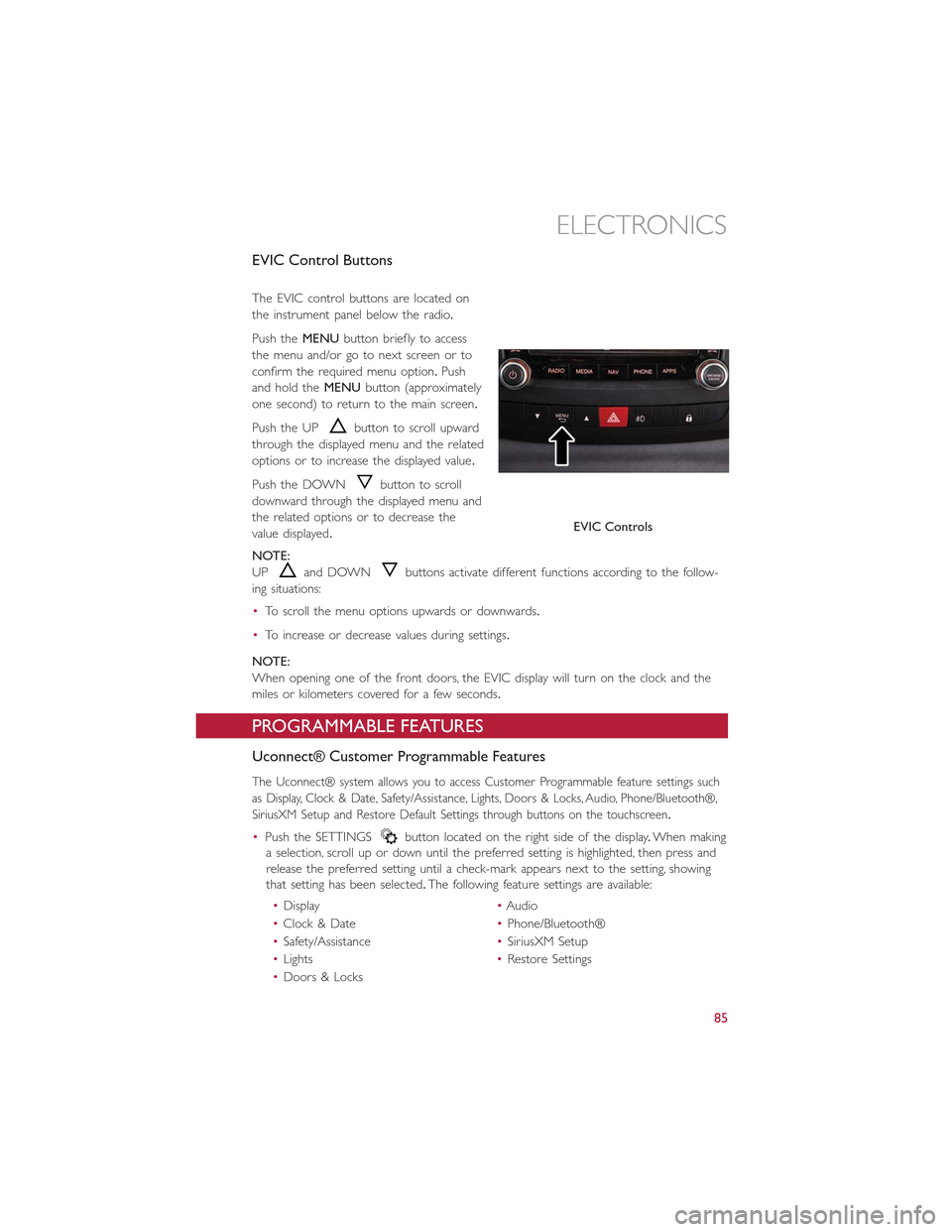
EVIC Control Buttons
The EVIC control buttons are located on
the instrument panel below the radio.
Push theMENUbutton briefly to access
the menu and/or go to next screen or to
confirm the required menu option.Push
and hold theMENUbutton (approximately
one second) to return to the main screen.
Push the UPbutton to scroll upward
through the displayed menu and the related
options or to increase the displayed value.
Push the DOWNbutton to scroll
downward through the displayed menu and
the related options or to decrease the
value displayed.
NOTE:
UPand DOWNbuttons activate different functions according to the follow-
ing situations:
•To scroll the menu options upwards or downwards.
•To increase or decrease values during settings.
NOTE:
When opening one of the front doors, the EVIC display will turn on the clock and the
miles or kilometers covered for a few seconds.
PROGRAMMABLE FEATURES
Uconnect® Customer Programmable Features
The Uconnect® system allows you to access Customer Programmable feature settings such
as Display, Clock & Date, Safety/Assistance, Lights, Doors & Locks, Audio, Phone/Bluetooth®,
SiriusXM Setup and Restore Default Settings through buttons on the touchscreen.
•Push the SETTINGSbutton located on the right side of the display.When making
a selection, scroll up or down until the preferred setting is highlighted, then press and
release the preferred setting until a check-mark appears next to the setting, showing
that setting has been selected.The following feature settings are available:
•Display•Audio
•Clock & Date•Phone/Bluetooth®
•Safety/Assistance•SiriusXM Setup
•Lights•Restore Settings
•Doors & Locks
EVIC Controls
ELECTRONICS
85
Page 90 of 148
Using HomeLink®
To operate, push and release the programmed HomeLink®button.Activation will
now occur for the programmed device (i.e., garage door opener, gate operator, security
system, entry door lock, home/office lighting, etc.,).The hand-held transmitter of the de-
vice may also be used at any time.
WARNING!
•Your motorized door or gate will open and close while you are programming the
universal transceiver.Do not program the transceiver if people or pets are in the
path of the door or gate.
•Do not run your vehicle in a closed garage or confined area while programming
the transceiver.Exhaust gas from your vehicle contains Carbon Monoxide (CO)
which is odorless and colorless.Carbon Monoxide is poisonous when inhaled and
can cause you and others to be severely injured or killed.
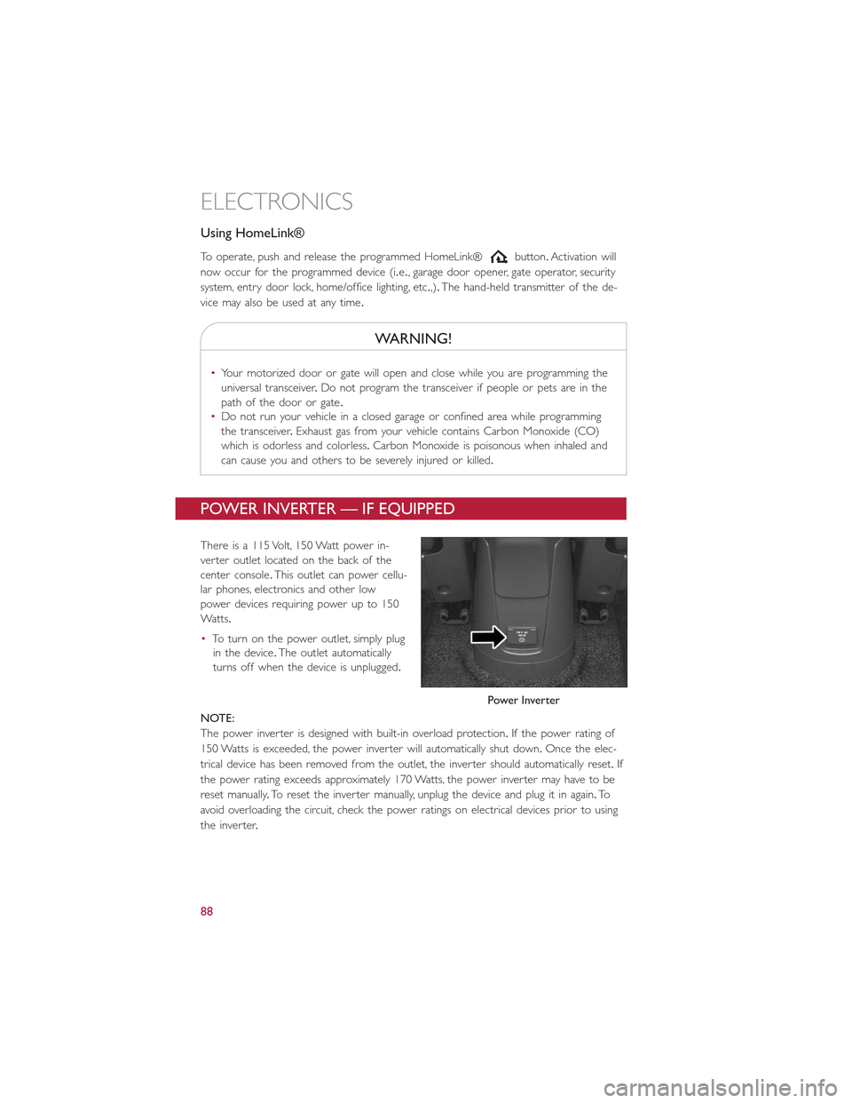
POWER INVERTER — IF EQUIPPED
There is a 115 Volt, 150 Watt power in-
verter outlet located on the back of the
center console.This outlet can power cellu-
lar phones, electronics and other low
power devices requiring power up to 150
Wa t t s.
•To turn on the power outlet, simply plug
in the device.The outlet automatically
turns off when the device is unplugged.
NOTE:
The power inverter is designed with built-in overload protection.If the power rating of
150 Watts is exceeded, the power inverter will automatically shut down.Once the elec-
trical device has been removed from the outlet, the inverter should automatically reset.If
the power rating exceeds approximately 170 Watts, the power inverter may have to be
reset manually.To reset the inverter manually, unplug the device and plug it in again.To
avoid overloading the circuit, check the power ratings on electrical devices prior to using
the inverter.
Power Inverter
ELECTRONICS
88
Page 123 of 148
OPENING THE HOOD
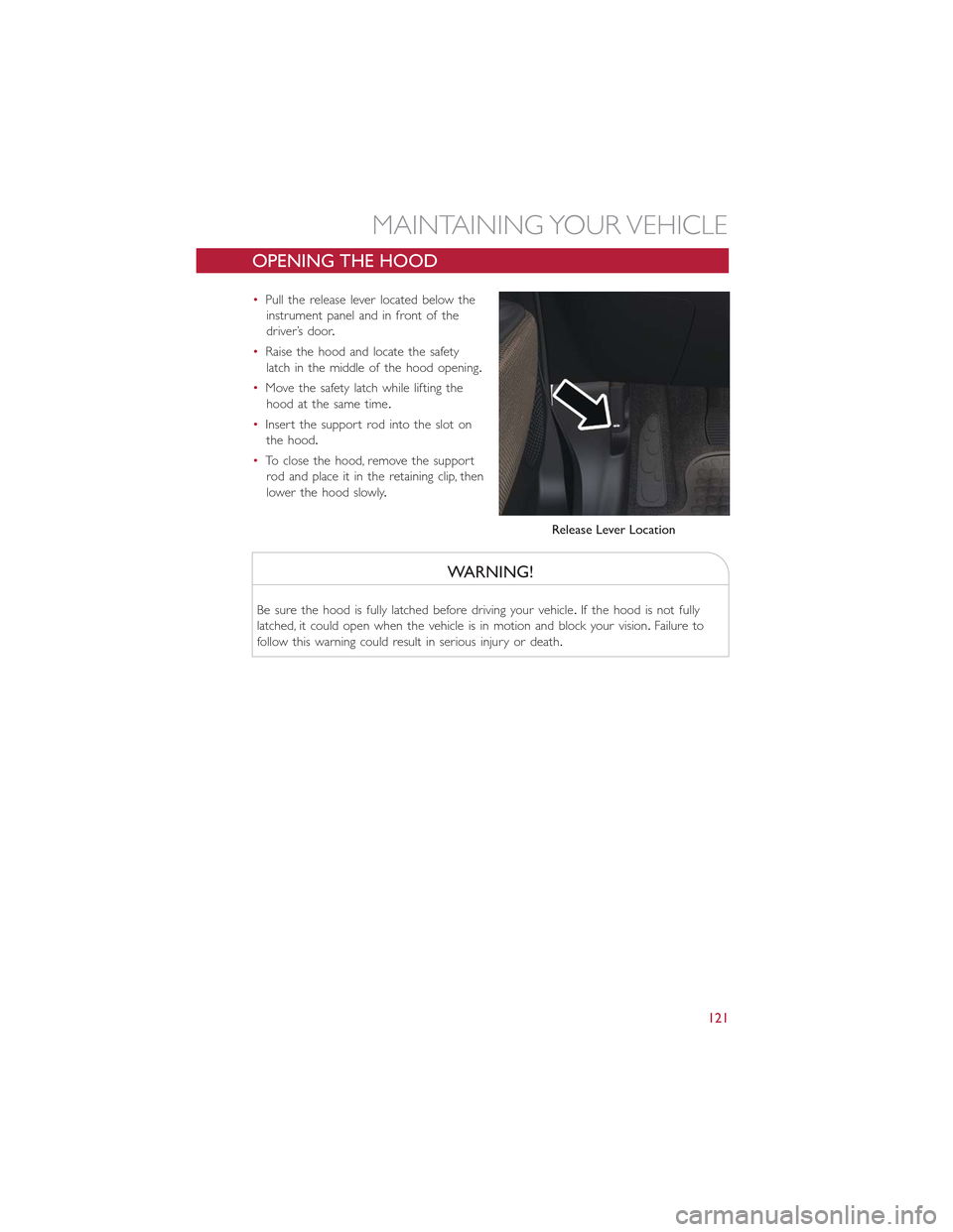
•Pull the release lever located below the
instrument panel and in front of the
driver’s door.
•Raise the hood and locate the safety
latch in the middle of the hood opening.
•Move the safety latch while lifting the
hood at the same time.
•Insert the support rod into the slot on
the hood.
•To close the hood, remove the support
rod and place it in the retaining clip, then
lower the hood slowly.
WARNING!
Be sure the hood is fully latched before driving your vehicle.If the hood is not fully
latched, it could open when the vehicle is in motion and block your vision.Failure to
follow this warning could result in serious injury or death.
Release Lever Location
MAINTAINING YOUR VEHICLE
121
Page 133 of 148
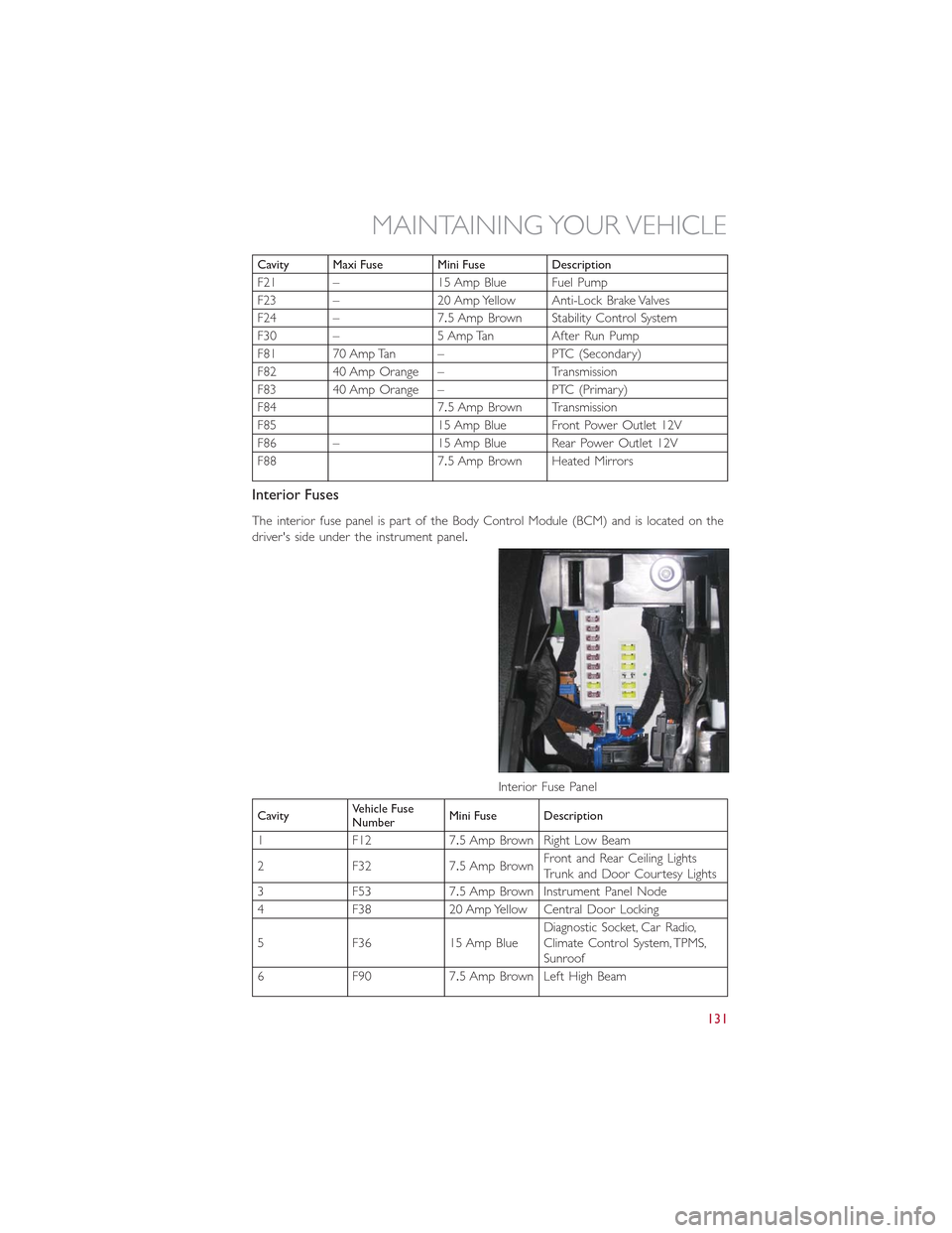
Cavity Maxi Fuse Mini Fuse Description
F21 – 15 Amp Blue Fuel Pump
F23 – 20 Amp Yellow Anti-Lock Brake Valves
F24 – 7.5 Amp Brown Stability Control System
F30 – 5 Amp Tan After Run Pump
F81 70 Amp Tan – PTC (Secondary)
F82 40 Amp Orange – Transmission
F83 40 Amp Orange – PTC (Primary)
F84 7.5 Amp Brown Transmission
F85 15 Amp Blue Front Power Outlet 12V
F86 – 15 Amp Blue Rear Power Outlet 12V
F88 7.5 Amp Brown Heated Mirrors
Interior Fuses
The interior fuse panel is part of the Body Control Module (BCM) and is located on the
driver's side under the instrument panel.
CavityVehicle FuseNumberMini Fuse Description
1 F12 7.5 Amp Brown Right Low Beam
2 F32 7.5 Amp BrownFront and Rear Ceiling LightsTr u n k a n d D o o r C o u r t e s y L i g h t s
3 F53 7.5 Amp Brown Instrument Panel Node
4 F38 20 Amp Yellow Central Door Locking
5 F36 15 Amp BlueDiagnostic Socket, Car Radio,Climate Control System, TPMS,Sunroof
6 F90 7.5 Amp Brown Left High Beam
Interior Fuse Panel
MAINTAINING YOUR VEHICLE
131