steering FIAT 500L 2015 2.G User Guide
[x] Cancel search | Manufacturer: FIAT, Model Year: 2015, Model line: 500L, Model: FIAT 500L 2015 2.GPages: 148, PDF Size: 3.77 MB
Page 3 of 148
INTRODUCTION/WELCOMEWELCOME FROM FIAT...............2
CONTROLS AT A GLANCEDRIVER COCKPIT..................4INSTRUMENT CLUSTER...............6
GETTING STARTEDKEY FOB.......................8VEHICLE SECURITY ALARM............9POWER DOOR LOCKS...............9SEAT BELT SYSTEMS................11SUPPLEMENTAL RESTRAINT SYSTEM (SRS) —AIR BAGS......................12CHILD RESTRAINTS................15HEAD RESTRAINTS.................19FRONT SEATS....................22REAR SEATS.....................23HEATED SEATS...................24TILT/TELESCOPING STEERING COLUMN...25
OPERATING YOUR VEHICLEENGINE BREAK-IN RECOMMENDATIONS...26TURN SIGNAL/LIGHTS/HIGH BEAM LEVER...26WIPER/WASHER LEVER..............28ELECTRONIC SPEED CONTROL.........29MANUAL CLIMATE CONTROLS.........31AUTOMATIC TEMPERATURE CONTROLS(ATC).........................32REAR PARK ASSIST.................33POWER SUNROOF.................33EURO TWIN CLUTCH SIX-SPEEDTRANSMISSION...................34ADDING FUEL...................37ELECTRONIC STABILITY CONTROL (ESC)...38
ELECTRONICSYO U R V E H I C L E ' S S O U N D S YS T E M.......40IDENTIFYING YOUR RADIO............42Uconnect® 5.0...................43Uconnect® 6.5N..................55Uconnect® PHONE.................74STEERING WHEEL AUDIO CONTROLS.....84ELECTRONIC VEHICLE INFORMATIONCENTER (EVIC)...................84PROGRAMMABLE FEATURES...........85UNIVERSAL GARAGE DOOR OPENER(HomeLink®)....................86POWER INVERTER — IF EQUIPPED.......88
POWER OUTLET..................89
UTILITY
TRAILER TOWING.................90RECREATIONAL TOWING (BEHINDMOTORHOME, ETC.)...............90
WHAT TO DO IN EMERGENCIES
ROADSIDE ASSISTANCE..............92INSTRUMENT CLUSTER WARNING LIGHTS..92INSTRUMENT CLUSTER INDICATOR LIGHTS..96IF YOUR ENGINE OVERHEATS..........98JACKING AND TIRE CHANGING.........99TIRE SERVICE KIT.................107JUMP-STARTING PROCEDURE..........113SHIFT LEVER OVERRIDE.............116TOW I N G A D I S A B L E D V E H I C L E.........116FREEING A STUCK VEHICLE...........118EVENT DATA RECORDER (EDR)........120CAP-LESS FUEL FILL FUNNEL..........120
MAINTAINING YOUR VEHICLEOPENING THE HOOD..............121ENGINE COMPARTMENT............122FLUID CAPACITIES................124FLUIDS, LUBRICANTS AND GENUINEPA RT S.......................124MAINTENANCE PROCEDURES.........126MAINTENANCE SCHEDULE...........126FUSES........................130TIRE PRESSURES.................133SPARE TIRES — IF EQUIPPED..........134WHEEL AND WHEEL TRIM CARE.......135REPLACEMENT BULBS..............136
CONSUMER ASSISTANCEFIAT CUSTOMER CENTER............137FIAT CANADA CUSTOMER CENTER......137ASSISTANCE FOR THE HEARING IMPAIRED..137PUBLICATIONS ORDERING...........137REPORTING SAFETY DEFECTS IN THEUNITED STATES..................138
MOPAR ACCESSORIESAUTHENTIC ACCESSORIES BY MOPAR®...139
FREQUENTLY ASKED QUESTIONSFREQUENTLY ASKED QUESTIONS.......140
INDEX......................141
TABLE OF CONTENTS
1
Page 6 of 148
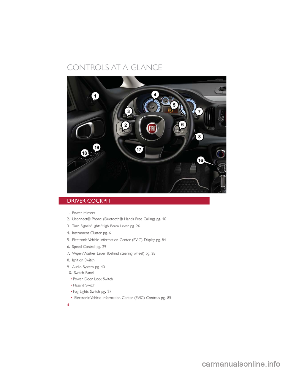
DRIVER COCKPIT
1.Power Mirrors
2.Uconnect® Phone (Bluetooth® Hands Free Calling) pg.40
3.Turn Signals/Lights/High Beam Lever pg.26
4.Instrument Cluster pg.6
5.Electronic Vehicle Information Center (EVIC) Display pg.84
6.Speed Control pg.29
7.Wiper/Washer Lever (behind steering wheel) pg.28
8.Ignition Switch
9.Audio System pg.40
10.Switch Panel
•Power Door Lock Switch
•Hazard Switch
•Fog Lights Switch pg.27
•Electronic Vehicle Information Center (EVIC) Controls pg.85
CONTROLS AT A GLANCE
4
Page 7 of 148
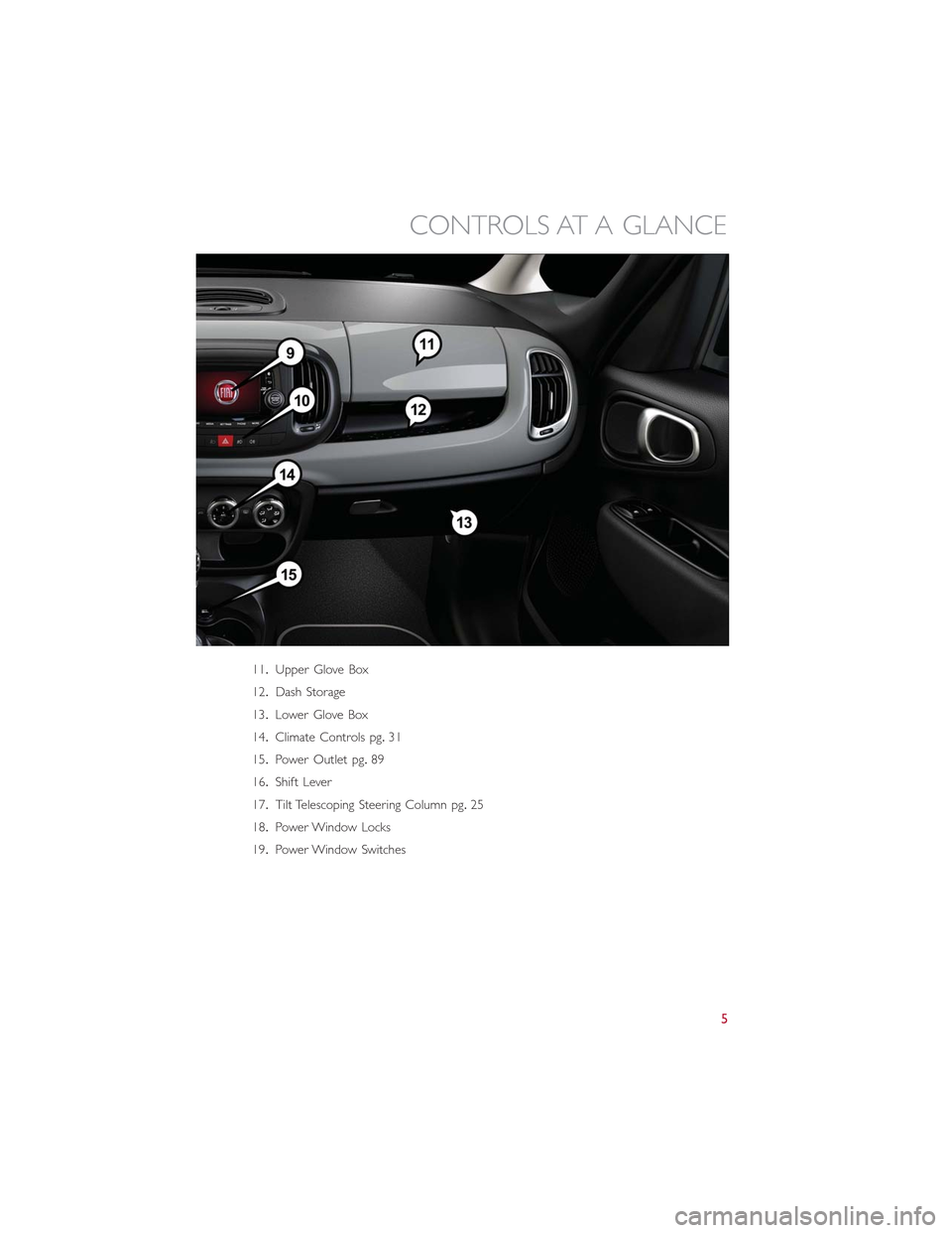
11.Upper Glove Box
12.Dash Storage
13.Lower Glove Box
14.Climate Controls pg.31
15.Power Outlet pg.89
16.Shift Lever
17.Tilt Telescoping Steering Column pg.25
18.Power Window Locks
19.Power Window Switches
CONTROLS AT A GLANCE
5
Page 14 of 148
SUPPLEMENTAL RESTRAINT SYSTEM (SRS) — AIR BAGS
Air Bag System Components
Your vehicle may be equipped with the following air bag system components:
•Occupant Restraint Controller (ORC)
•Air Bag Warning Light
•Steering Wheel and Column
•Instrument Panel
•Knee Impact Bolsters
•Advanced Front Air Bags
•Supplemental Side Air Bags
•Supplemental Knee Air Bags
•Front and Side Impact Sensors
•Seat Belt Pretentioners
•Seat Belt Buckle Switch
•Seat Track Position Sensors
Advanced Front Air Bags
•This vehicle has Advanced Front Air Bags for both the driver and front passenger as a
supplement to the seat belt restraint systems.The Advanced Front Air Bags will not
deploy in every type of collision.
•Advanced Front Air Bags are designed to provide additional protection by supplement-
ing the seat belts.Advanced Front Air Bags are not expected to reduce the risk of
injury in rear, side, or rollover collisions.
•The Advanced Front Air Bags will not deploy in all frontal collisions, including some that
may produce substantial vehicle damage — for example, some pole collisions, truck
underrides, and angle offset collisions.
•On the other hand, depending on the type and location of impact, Advanced Front Air
Bags may deploy in crashes with little vehicle front-end damage but that produce a
severe initial deceleration.
•Because air bag sensors measure vehicle deceleration over time, vehicle speed and
damage by themselves are not good indicators of whether or not an air bag should
have deployed.
•Seat belts are necessary for your protection in all collisions, and also are needed to
help keep you in position, away from an inflating air bag.
•The air bags must be ready to inflate for your protection in a collision.The Occupant
Restraint Controller (ORC) monitors the internal circuits and interconnecting wiring
associated with air bag system electrical components.
GETTING STARTED
12
Page 15 of 148
•The ORC turns on the Air Bag Warning Light in the instrument panel for approxi-
mately four to eight seconds for a self-check when the ignition switch is first turned to
the ON/RUN position.After the self-check, the Air Bag Warning Light will turn off.If
the ORC detects a malfunction in any part of the system, it turns on the Air Bag
Warning Light, either momentarily or continuously.A single chime will sound to alert
you if the light comes on again after initial startup.
•The ORC monitors the readiness of the electronic parts of the air bag system when-
ever the ignition switch is in the START or ON/RUN position.If the ignition switch is
in the OFF position or in the ACC position, the air bag system is not on and the air
bags will not inflate.
•If the Air Bag Warning Light in the instrument panel is not on during the four to eight
seconds when the ignition switch is first turned to the ON/RUN position, stays on, or
turns on while driving, have the vehicle serviced by an authorized service center imme-
diately.
NOTE:
If the speedometer, tachometer, or any engine related gauges are not working, the Occu-
pant Restraint Controller (ORC) may also be disabled.In this condition the air bags may
not be ready to inflate for your protection.Have an authorized dealer service the air bag
system immediately.
•After any collision, the vehicle should be taken to an authorized dealer immediately.
•Do not drive your vehicle after the air bags have deployed.If you are involved in an-
other collision, the air bags will not be in place to protect you.
•If it is necessary to modify the air bag system for persons with disabilities, contact your
authorized dealer.
•Refer to “Supplemental Restraint System (SRS)” in “Things To Know Before Starting
Your Vehicle” in the Owner's Manual on the DVD for further information.
Supplemental Knee Air Bags
This vehicle is equipped with a Supplemental Driver Knee Air Bag mounted in the instru-
ment panel below the steering column.The Supplemental Driver Knee Air Bag provides
enhanced protection during a frontal impact by working together with the seat belts, pre-
tensioners, and Advanced Front Air Bags.
GETTING STARTED
13
Page 16 of 148
WARNING!
•Relying on the air bags alone could lead to more severe injuries in a collision.The
air bags work with your seat belt to restrain you properly.In some collisions, the
air bags won't deploy at all.Always wear your seat belts even though you have air
bags.
•Being too close to the steering wheel or instrument panel during Advanced Front
Air Bag deployment could cause serious injury, including death.Air bags need
room to inflate.Sit back, comfortably extending your arms to reach the steering
wheel or instrument panel.
•No objects should be placed over or near the air bag on the instrument panel or
steering wheel because any such objects could cause harm if the vehicle is in a
collision severe enough to cause the air bag to inflate.
Supplemental Side Air Bags
•This vehicle is equipped with Supplemental Seat-Mounted Side Air Bags (SABs) located
in the outboard side of the front seats.The SABs are marked with a SRS AIRBAG or
AIRBAG label sewn into the outboard side of the seats.
•This vehicle is equipped with Supplemental Side Air Bag Inflatable Curtains (SABICs)
located above the side windows.The trim covering the SABICs is labeled SRS AIRBAG
or AIRBAG.The SABICs may help reduce the risk of partial or complete ejection of
vehicle occupants through side windows in cer tain side impact events.
•The SABICs and SABs (“Side Air Bags”) are designed to activate in certain side impacts
and certain rollover events (if equipped with rollover sensing).The Occupant Restraint
Controller (“ORC”) determines whether the deployment of the Side Air Bags in a
particular side impact or rollover event (if equipped with rollover sensing) is appropri-
ate, based on the severity and type of collision.Ve h i c l e d a m a g e b y i t s e l f i s n o t a g o o d
indicator of whether or not Side Air Bags should have deployed.
GETTING STARTED
14
Page 27 of 148
TILT/TELESCOPING STEERING COLUMN
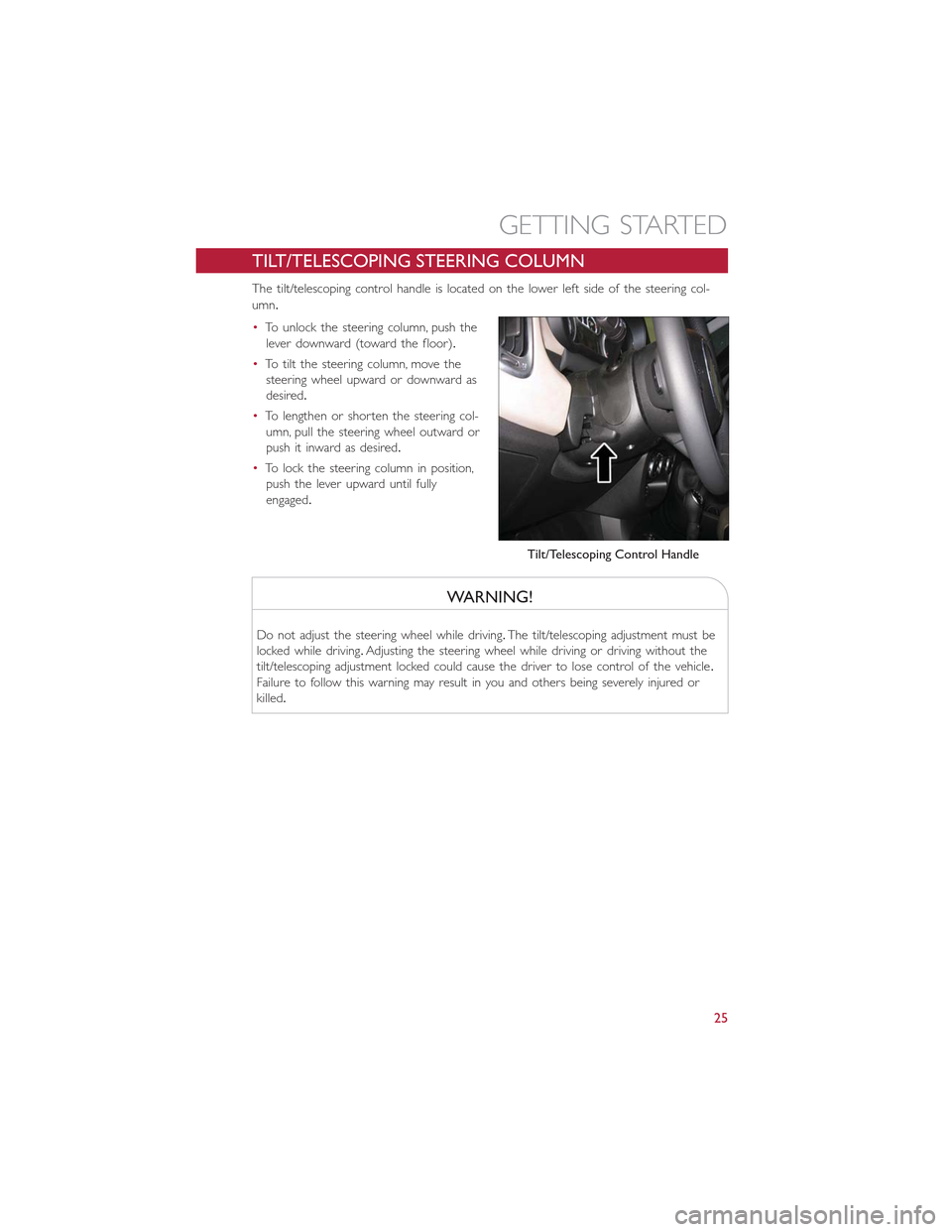
The tilt/telescoping control handle is located on the lower left side of the steering col-
umn.
•To unlock the steering column, push the
lever downward (toward the floor).
•To tilt the steering column, move the
steering wheel upward or downward as
desired.
•To lengthen or shorten the steering col-
umn, pull the steering wheel outward or
push it inward as desired.
•To lock the steering column in position,
push the lever upward until fully
engaged.
WARNING!
Do not adjust the steering wheel while driving.The tilt/telescoping adjustment must be
locked while driving.Adjusting the steering wheel while driving or driving without the
tilt/telescoping adjustment locked could cause the driver to lose control of the vehicle.
Failure to follow this warning may result in you and others being severely injured or
killed.
Tilt/Telescoping Control Handle
GETTING STARTED
25
Page 29 of 148
High Beams
•Pull the lever rearward to activate the high beams.
•A high beam symbol will illuminate in the cluster to indicate the high beams are on.
NOTE:
For safe driving, turn off the high beams when oncoming traffic is present to prevent
headlight glare and as a courtesy to other motorists.
Flash To Pass
•Pull the lever toward you to activate the high beams.The high beams will remain on
until the lever is released.
Headlight Delay (Follow Me Home)
•Within two minutes of the ignition switch being turned to the OFF/LOCK position or
the ignition key being removed from the ignition, pull the turn signal lever toward the
steering wheel.
•Each movement of the lever toward the steering wheel will increase the illumination
period by 30 seconds, up to a maximum of 210 seconds.
•To deactivate, pull the multifunction lever toward the steering wheel and hold it for
more than two seconds.
NOTE:
Activation of Follow Me Home is only enabled once per key cycle and the steps outlined
above must be repeated each time you want to activate it.
Fog Lights
•Push the fog light button, located on the center stack of the instrument panel just be-
low the radio, once to turn on the fog lights.
•Push the button a second time to turn the fog lights off.
OPERATING YOUR VEHICLE
27
Page 31 of 148
ELECTRONIC SPEED CONTROL
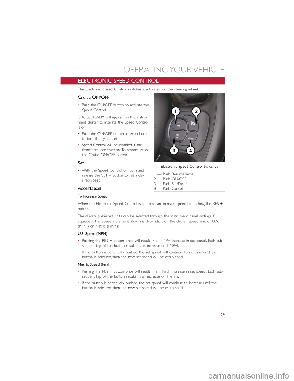
The Electronic Speed Control switches are located on the steering wheel.
Cruise ON/OFF
•Push the ON/OFF button to activate the
Speed Control.
CRUISE READY will appear on the instru-
ment cluster to indicate the Speed Control
is on.
•Push the ON/OFF button a second time
to turn the system off.
•Speed Control will be disabled if the
front tires lose traction.To restore, push
the Cruise ON/OFF button.
Set
•With the Speed Control on, push and
release the SET – button to set a de-
sired speed.
Accel/Decel
To Increase Speed
When the Electronic Speed Control is set, you can increase speed by pushing the RES+
button.
The drivers preferred units can be selected through the instrument panel settings if
equipped.The speed increment shown is dependant on the chosen speed unit of U.S.
(MPH) or Metric (km/h):
U.S. Speed (MPH)
•Pushing the RES+button once will result in a 1 MPH increase in set speed.Each sub-
sequent tap of the button results in an increase of 1 MPH.
•If the button is continually pushed, the set speed will continue to increase until the
button is released, then the new set speed will be established.
Metric Speed (km/h)
•Pushing the RES+button once will result in a 1 km/h increase in set speed.Each sub-
sequent tap of the button results in an increase of 1 km/h.
•If the button is continually pushed, the set speed will continue to increase until the
button is released, then the new set speed will be established.
Electronic Speed Control Switches
1 — Push Resume/Accel2 — Push ON/OFF3 — Push Set/Decel4 — Push Cancel
OPERATING YOUR VEHICLE
29
Page 42 of 148
YOUR VEHICLE'S SOUND SYSTEM
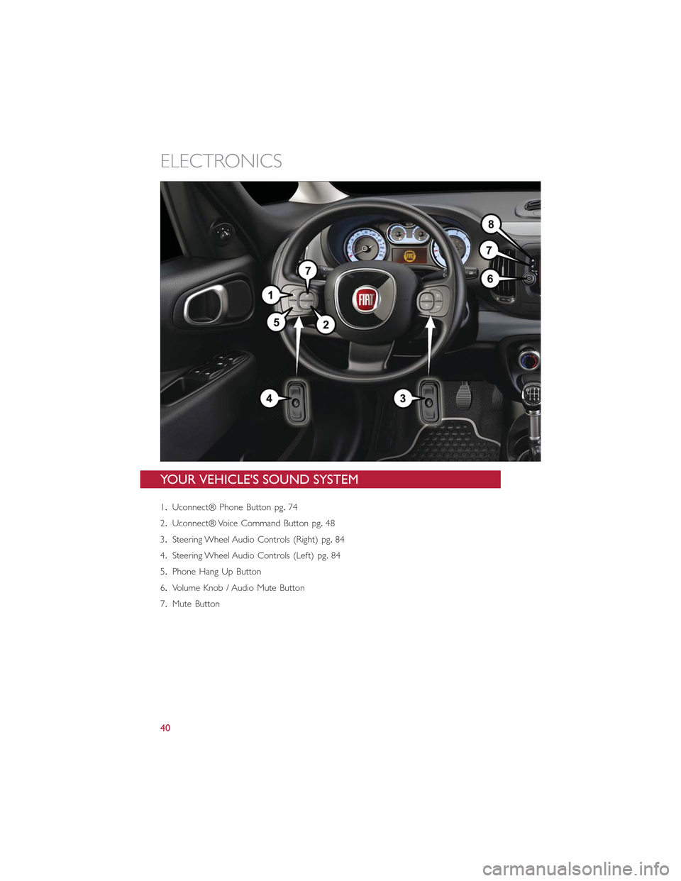
1.Uconnect® Phone Button pg.74
2.Uconnect® Voice Command Button pg.48
3.Steering Wheel Audio Controls (Right) pg.84
4.Steering Wheel Audio Controls (Left) pg.84
5.Phone Hang Up Button
6.Volume Knob / Audio Mute Button
7.Mute Button
ELECTRONICS
40