trailer FIAT 500L 2018 Owner handbook (in English)
[x] Cancel search | Manufacturer: FIAT, Model Year: 2018, Model line: 500L, Model: FIAT 500L 2018Pages: 268, PDF Size: 4.87 MB
Page 80 of 268
The "Reset" procedure must be carried
out:
each time tyre pressure is modified;
when even only one tyre is changed;
when tyres are rotated/inverted;
when the space-saver wheel is
fitted.
Before carrying out the “Reset”
procedure, inflate the tyres to the rated
pressure values specified in the inflation
pressure table (see "Wheels" paragraph
in the "Technical specifications"
chapter).
If the “Reset” procedure is not carried
out, in all above cases, the
warning
light may give false indications on
one or more tyres.
To carry out the “Reset” procedure,
with the car stopped and the ignition
device at MAR, use the Setup Menu on
the display as follows:
go to "Vehicle info" and then to
"Reset tyres";
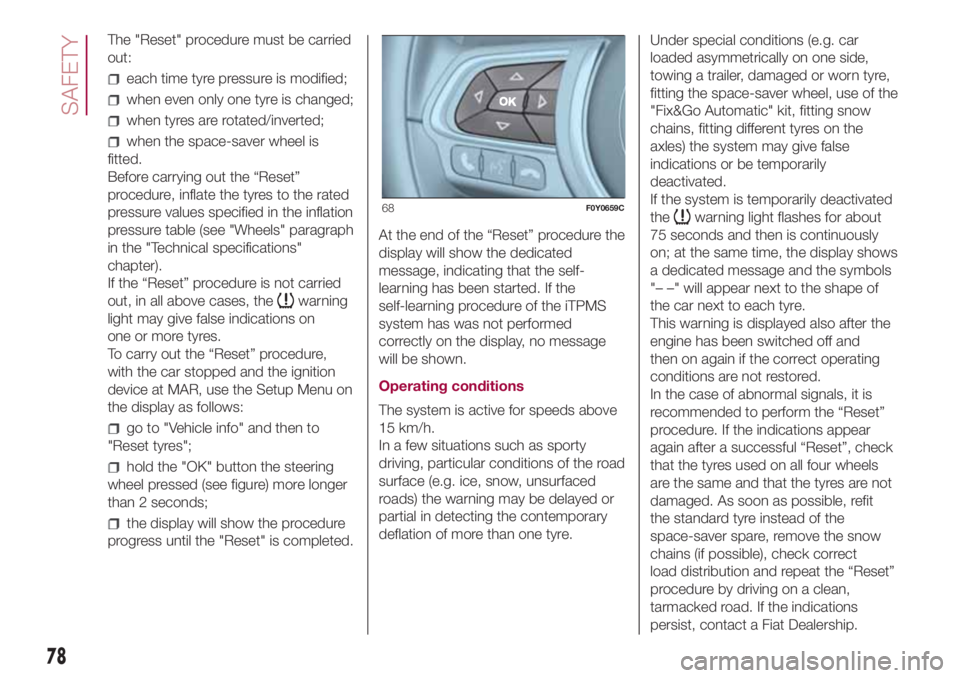
hold the "OK" button the steering
wheel pressed (see figure) more longer
than 2 seconds;
the display will show the procedure
progress until the "Reset" is completed.At the end of the “Reset” procedure the
display will show the dedicated
message, indicating that the self-
learning has been started. If the
self-learning procedure of the iTPMS
system has was not performed
correctly on the display, no message
will be shown.
Operating conditions
The system is active for speeds above
15 km/h.
In a few situations such as sporty
driving, particular conditions of the road
surface (e.g. ice, snow, unsurfaced
roads) the warning may be delayed or
partial in detecting the contemporary
deflation of more than one tyre.Under special conditions (e.g. car
loaded asymmetrically on one side,
towing a trailer, damaged or worn tyre,
fitting the space-saver wheel, use of the
"Fix&Go Automatic" kit, fitting snow
chains, fitting different tyres on the
axles) the system may give false
indications or be temporarily
deactivated.
If the system is temporarily deactivated
the
warning light flashes for about
75 seconds and then is continuously
on; at the same time, the display shows
a dedicated message and the symbols
"– –" will appear next to the shape of
the car next to each tyre.
This warning is displayed also after the
engine has been switched off and
then on again if the correct operating
conditions are not restored.
In the case of abnormal signals, it is
recommended to perform the “Reset”
procedure. If the indications appear
again after a successful “Reset”, check
that the tyres used on all four wheels
are the same and that the tyres are not
damaged. As soon as possible, refit
the standard tyre instead of the
space-saver spare, remove the snow
chains (if possible), check correct
load distribution and repeat the “Reset”
procedure by driving on a clean,
tarmacked road. If the indications
persist, contact a Fiat Dealership.68F0Y0659C
78
SAFETY
Page 81 of 268
WARNING
64)The system is an aid for the driver, who
must always pay full attention while
driving. The responsibility always rests with
the driver, who must take into account
the traffic conditions in order to drive
in complete safety. The driver must always
maintain a safe distance from the vehicle
in front.
65)If the driver depresses the brake pedal
fully or carries out a fast steering during
system operation, the automatic braking
function may stop (e.g. to allow a possible
manoeuvre to avoid the obstacle).
66)The laser beam is not visible at the
naked eye. Do not look directly, or with
optical instruments (e.g. lenses), at the
laser beam from a distance lower than 10
cm: this may cause damage to the sight.
The laser beam is also present when
the key is at MAR but its operation is off,
not available or manually deactivated
with the display Setup Menu.
67)The system intervenes on vehicles
travelling in the same lane. Small sized
vehicles (e.g. bicycles or motorbikes)
or people, animals and things (e.g.
pushchairs) and more in general all those
obstacles with a low reflection of the light
emitted by the laser (e.g. vehicles soiled
with mud) are not taken into consideration.68)If the car must be placed on a roller
bench (at a speed within 5 and 30 km/h)
for maintenance interventions or if it is
washed in an automatic roller washing
tunnel with an obstacle in the front part
(e.g. another car, a wall or another
obstacle), the system may detect its
presence and activate. In this case the
system must be deactivated through the
display Setup Menu.
WARNING
35)The laser sensor may have limited or
absent operation due to weather
conditions such as: heavy rain, hail, thick
fog, heavy snow, formation of ice layers on
the windscreen.
36)Sensor operation may also be
compromised by the presence of dust,
condensation, dirt or ice on the
windscreen, by traffic conditions (e.g.
vehicles that are driving not aligned with
your car, vehicle driving in a transverse or
opposite way on the same lane, bend with
a small radius of curvature), by road
surface conditions and by driving
conditions (e.g. off-road driving). Make sure
the windscreen is always clean. Use
specific detergents and clean cloths to
avoid scratching the windscreen. The
sensor operation may also be limited or
absent in some driving, traffic and road
surface conditions.
37)Projecting loads on the roof of the car
may interfere with the correct operation
of the sensor. Before starting make sure
the load is correctly positioned, in order not
to cover the sensor operating range.38)If the windscreen must be replaced
due to scratches, chipping or breakage,
contact exclusively a Fiat Dealership.
Do not replace the windscreen on your
own, risk of malfunction! It is advisable to
replace the windscreen if it is damaged
in the laser sensor area.
39)Do not tamper nor operate on the laser
sensor. Do not close the openings in the
aesthetic cover located under the interior
rear view mirror. In the event of a sensor
failure, contact a Fiat Dealership.
40)If you are driving on roads close to
trees with protruding branches it is
advisable to deactivate the system to
prevent the branches at the height of the
bonnet or the windscreen from interfering
with the system.
41)Do not cover the operating range of the
sensor with stickers or other objects. Also
pay attention to other objects on the
bonnet (e.g. a layer of snow) and make
sure they do not interfere with the light
emitted by the laser.
42)If a trailer or a vehicle is towed the
system must be deactivated with the
display Setup Menu.
43)If the system signals a loss of pressure
on a specific tyre, it is recommended to
check the pressure on all four tyres.
44)The iTPMS does not relieve the driver
from the obligation to check the tyre
pressure every month; it is not even to be
considered a replacement system for
maintenance or a safety system.
79
Page 104 of 268
STARTING AND DRIVING
Let’s get to the core of the vehicle:
seeing how you can exploit all of its
potential to the full.
We’ll look at how to drive it safely in any
situation, so that it can be a welcome
companion, with our comfort and
our wallets in mind.STARTING THE ENGINE .................103
WHEN PARKED ..............................104
HANDBRAKE ..................................105
USING THE MANUAL GEARBOX ....105
USING THE DUALOGIC
GEARBOX.......................................106
START&STOP SYSTEM ..................108
CRUISE CONTROL (CONSTANT
SPEED REGULATOR) .....................109
SPEED LIMITER ..............................111
MODE SELECTOR ..........................112
PARKING SENSORS.......................115
REAR BACKUP CAMERA
(PARKVIEW® REAR BACKUP
CAMERA) ........................................116
TOWING TRAILERS ........................117
REFUELLING THE VEHICLE ...........118
102
STARTING AND DRIVING
Page 117 of 268
PARKING SENSORS
114)58)
SENSORS
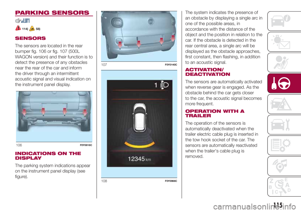
The sensors are located in the rear
bumper fig. 106 or fig. 107 (500L
WAGON version) and their function is to
detect the presence of any obstacles
near the rear of the car and inform
the driver through an intermittent
acoustic signal and visual indication on
the instrument panel display.
INDICATIONS ON THE
DISPLAY
The parking system indications appear
on the instrument panel display (see
figure).The system indicates the presence of
an obstacle by displaying a single arc in
one of the possible areas, in
accordance with the distance of the
object and the position in relation to the
car. If the obstacle is detected in the
rear central area, a single arc will be
displayed as the obstacle approaches,
first constant, then flashing, in addition
to an acoustic signal.
ACTIVATION/
DEACTIVATION
The sensors are automatically activated
when reverse gear is engaged. As the
obstacle behind the car gets closer
to the car, the acoustic signal becomes
more frequent.
OPERATION WITH A
TRAILER
The operation of the sensors is
automatically deactivated when the
trailer electric cable plug is inserted in
the tow hook socket of the car. The
sensors are automatically reactivated
when the trailer's cable plug is
removed.
106F0Y0616C
107F0Y0140C
108F0Y0966C
115
Page 119 of 268
SYMBOLS AND
MESSAGES ON THE
DISPLAY
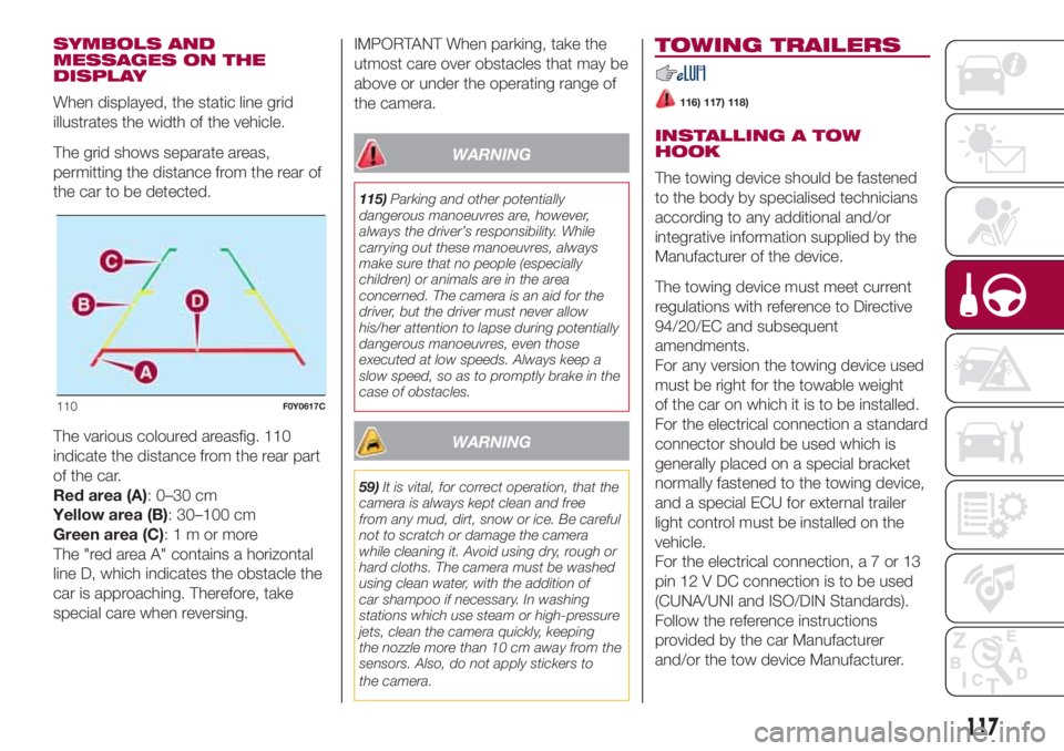
When displayed, the static line grid
illustrates the width of the vehicle.
The grid shows separate areas,
permitting the distance from the rear of
the car to be detected.
The various coloured areasfig. 110
indicate the distance from the rear part
of the car.
Red area (A): 0–30 cm
Yellow area (B): 30–100 cm
Green area (C):1mormore
The "red area A" contains a horizontal
line D, which indicates the obstacle the
car is approaching. Therefore, take
special care when reversing.IMPORTANT When parking, take the
utmost care over obstacles that may be
above or under the operating range of
the camera.
WARNING
115)Parking and other potentially
dangerous manoeuvres are, however,
always the driver’s responsibility. While
carrying out these manoeuvres, always
make sure that no people (especially
children) or animals are in the area
concerned. The camera is an aid for the
driver, but the driver must never allow
his/her attention to lapse during potentially
dangerous manoeuvres, even those
executed at low speeds. Always keep a
slow speed, so as to promptly brake in the
case of obstacles.
WARNING
59)It is vital, for correct operation, that the
camera is always kept clean and free
from any mud, dirt, snow or ice. Be careful
not to scratch or damage the camera
while cleaning it. Avoid using dry, rough or
hard cloths. The camera must be washed
using clean water, with the addition of
car shampoo if necessary. In washing
stations which use steam or high-pressure
jets, clean the camera quickly, keeping
the nozzle more than 10 cm away from the
sensors. Also, do not apply stickers to
the camera.
TOWING TRAILERS
116) 117) 118)
INSTALLING A TOW
HOOK
The towing device should be fastened
to the body by specialised technicians
according to any additional and/or
integrative information supplied by the
Manufacturer of the device.
The towing device must meet current
regulations with reference to Directive
94/20/EC and subsequent
amendments.
For any version the towing device used
must be right for the towable weight
of the car on which it is to be installed.
For the electrical connection a standard
connector should be used which is
generally placed on a special bracket
normally fastened to the towing device,
and a special ECU for external trailer
light control must be installed on the
vehicle.
For the electrical connection,a7or13
pin 12 V DC connection is to be used
(CUNA/UNI and ISO/DIN Standards).
Follow the reference instructions
provided by the car Manufacturer
and/or the tow device Manufacturer.
110F0Y0617C
117
Page 120 of 268
IMPORTANT NOTES
For towing caravans or trailers the car
must be fitted with an approved tow
hook and an adequate electrical
system. Installation must be carried out
by specialised technicians.
Install any specific and/or additional
door mirrors as specified by the
Highway Code.
Remember that, when towing a trailer,
steep hills are harder to climb, braking
distances increase and overtaking
takes longer depending on the overall
weight of the trailer.
Engage a low gear when driving
downhill, rather than constantly using
the brake.
The weight the trailer exerts on the car
tow hook reduces the car's loading
capacity by the same amount. To make
sure that the maximum towable weight
is not exceeded (given in the vehicle
registration document) account should
be taken of the fully laden trailer,
including accessories and luggage.
Do not exceed the speed limits specific
to each country you are driving in, in
the case of vehicles towing trailers.
In any case, the top speed must not
exceed 100 km/h.Any electric brake (or electric winch,
etc.) should be supplied directly by the
battery through a cable with a section
of at least 2.5 mm
2.
In addition to the electrical branches,
the car electrical system can only
be connected to the supply cable for an
electric brake and to the cable for an
internal light for the trailer, not
exceeding 15 W. For connections, use
the preset control unit with a battery
cable with section not less than 2.5
mm
2.
IMPORTANT The use of auxiliary loads
other than external lights (electric brake,
winch, etc.) must take place with
engine running.
IMPORTANT To install a tow hook
contact a Fiat Dealership.
WARNING
116)The ABS with which the car is
equipped will not control the braking
system of the trailer. Particular caution is
required on slippery roads.
117)Never modify the braking system of
the vehicle to control the trailer brake. The
trailer braking system must be fully
independent of the vehicle’s hydraulic
system.
118)After fitting, screw holes must be
sealed to prevent a exhaust gas inlet.
REFUELLING THE
VEHICLE
119) 120) 121)60)
Before refuelling, make sure that the
fuel type is correct. During refuelling
procedure, switch off the engine,
engage handbrake, rotate the ignition
key to STOP and do not smoke.
PETROL ENGINES
Only use unleaded petrol with a number
of octanes (R.O.N.) not lower than 95
(EN228 specification).
DIESEL ENGINES
Only use Diesel for motor vehicles
(EN590 specification).
When using or parking the car for a
long time in the mountains or cold
areas, it is advisable to refuel using
locally available Diesel. In this case, it is
also advisable to keep the tank over
50% full.
REFUELLING
PROCEDURE
Diesel and petrol versions
Proceed as follows:
open the flap A fig. 111 pulling
outwards, insert the nozzle in the filler
and refuel;
118
STARTING AND DRIVING
Page 151 of 268
DEMANDING USE OF THE
CAR
If the vehicle is used in one of the
following conditions:
law enforcement (or security
service), taxi service;
towing a trailer or caravan;
dusty roads;
short, repeated journeys (less than
7-8 km) at sub-zero outside
temperatures;
engine often idling or driving long
distances at low speeds or long periods
of inactivity;
the following checks must be carried
out more often than indicated in the
Service Schedule:
check front disc brake pad condition
and wear;
check cleanliness of bonnet and
luggage compartment locks,
cleanliness and lubrication of linkage;
visually inspect conditions of:
engine, gearbox, transmission, pipes
and hoses (exhaust/fuel system/brakes)
and rubber elements (gaiters/sleeves/
bushes, etc.);
check battery charge and battery
fluid level (electrolyte);
visually inspect conditions of the
accessory drive belts;
check and, if necessary, change
engine oil and replace oil filter;
check and, if necessary, replace
pollen filter;
check and, if necessary, replace air
cleaner.
149
Page 177 of 268
IDENTIFICATION
DATA
VEHICLE IDENTIFICATION
NUMBER (VIN) PLATE
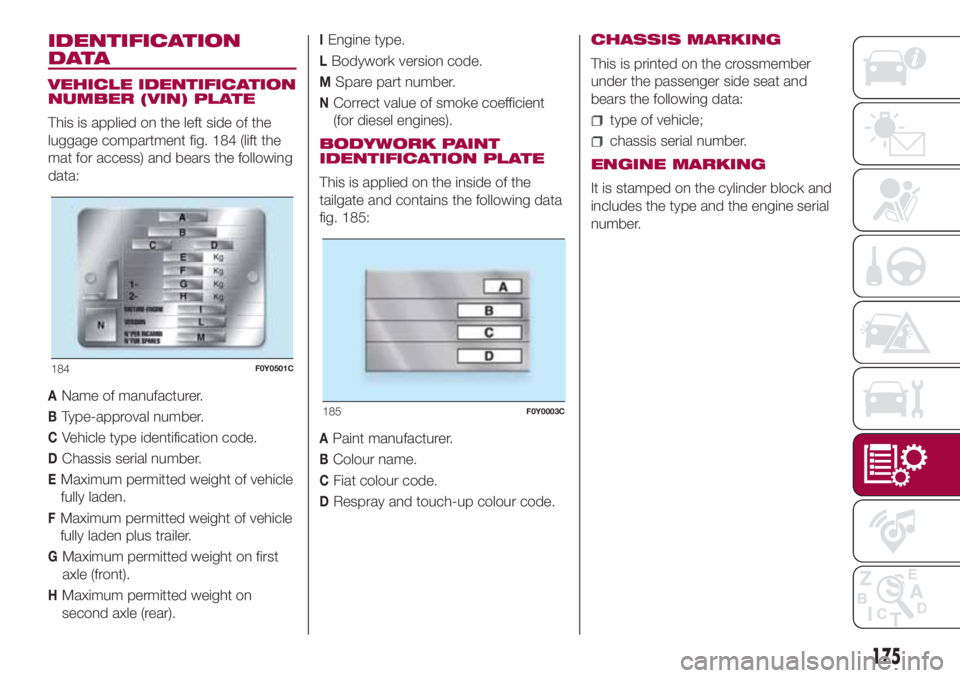
This is applied on the left side of the
luggage compartment fig. 184 (lift the
mat for access) and bears the following
data:
AName of manufacturer.
BType-approval number.
CVehicle type identification code.
DChassis serial number.
EMaximum permitted weight of vehicle
fully laden.
FMaximum permitted weight of vehicle
fully laden plus trailer.
GMaximum permitted weight on first
axle (front).
HMaximum permitted weight on
second axle (rear).
IEngine type.
LBodywork version code.
MSpare part number.
NCorrect value of smoke coefficient
(for diesel engines).
BODYWORK PAINT
IDENTIFICATION PLATE
This is applied on the inside of the
tailgate and contains the following data
fig. 185:
APaint manufacturer.
BColour name.
CFiat colour code.
DRespray and touch-up colour code.CHASSIS MARKING
This is printed on the crossmember
under the passenger side seat and
bears the following data:
type of vehicle;
chassis serial number.
ENGINE MARKING
It is stamped on the cylinder block and
includes the type and the engine serial
number.
184F0Y0501C
185F0Y0003C
175
Page 196 of 268
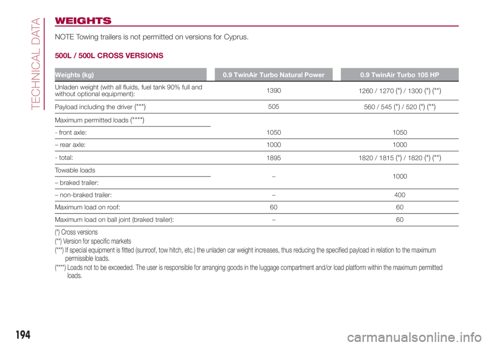
WEIGHTS
NOTE Towing trailers is not permitted on versions for Cyprus.
500L / 500L CROSS VERSIONS
Weights (kg) 0.9 TwinAir Turbo Natural Power 0.9 TwinAir Turbo 105 HP
Unladen weight (with all fluids, fuel tank 90% full and
without optional equipment):1390
1260 / 1270(*)/ 1300(*) (**)
Payload including the driver(***)505
560 / 545(*)/ 520(*) (**)
Maximum permitted loads(****)
1050 1050 - front axle:
– rear axle: 1000 1000
- total:
1895 1820 / 1815
(*)/ 1820(*) (**)
Towable loads
– 1000
– braked trailer:
– non-braked trailer: – 400
Maximum load on roof: 60 60
Maximum load on ball joint (braked trailer): – 60
(*) Cross versions
(**) Version for specific markets
(***) If special equipment is fitted (sunroof, tow hitch, etc.) the unladen car weight increases, thus reducing the specified payload in relation to the maximum
permissible loads.
(****) Loads not to be exceeded. The user is responsible for arranging goods in the luggage compartment and/or load platform within the maximum permitted
loads.
194
TECHNICAL DATA
Page 197 of 268
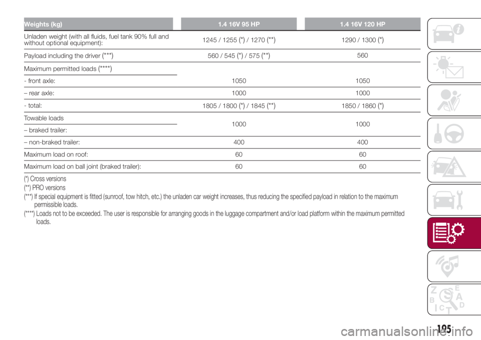
Weights (kg) 1.4 16V 95 HP 1.4 16V 120 HP
Unladen weight (with all fluids, fuel tank 90% full and
without optional equipment):1245 / 1255(*)/ 1270(**)1290 / 1300(*)
Payload including the driver(***)560 / 545(*)/ 575(**)560
Maximum permitted loads
(****)
1050 1050 - front axle:
– rear axle: 1000 1000
- total:
1805 / 1800
(*)/ 1845(**)1850 / 1860(*)
Towable loads
1000 1000
– braked trailer:
– non-braked trailer: 400 400
Maximum load on roof: 60 60
Maximum load on ball joint (braked trailer): 60 60
(*) Cross versions
(**) PRO versions
(***) If special equipment is fitted (sunroof, tow hitch, etc.) the unladen car weight increases, thus reducing the specified payload in relation to the maximum
permissible loads.
(****) Loads not to be exceeded. The user is responsible for arranging goods in the luggage compartment and/or load platform within the maximum permitted
loads.
195