lock FIAT 500L 2019 Owner handbook (in English)
[x] Cancel search | Manufacturer: FIAT, Model Year: 2019, Model line: 500L, Model: FIAT 500L 2019Pages: 248, PDF Size: 5.74 MB
Page 80 of 248
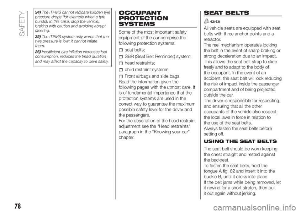
34)The iTPMS cannot indicate sudden tyre
pressure drops (for example when a tyre
bursts). In this case, stop the vehicle,
braking with caution and avoiding abrupt
steering.
35)The iTPMS system only warns that the
tyre pressure is low: it cannot inflate
them.
36)Insufficient tyre inflation increases fuel
consumption, reduces the tread duration
and may affect the capacity to drive safely.OCCUPANT
PROTECTION
SYSTEMS
Some of the most important safety
equipment of the car comprise the
following protection systems:
seat belts;
SBR (Seat Belt Reminder) system;
head restraints;
child restraint systems;
Front airbags and side bags.
Read the information given the
following pages with the utmost care. It
is of fundamental importance that the
protection systems are used in the
correct way to guarantee the maximum
possible safety level for the driver and
the passengers.
For the description of the head restraint
adjustment see the "Head restraints"
paragraph in the "Knowing your car"
chapter.
SEAT BELTS
62) 63)
All vehicle seats are equipped with seat
belts with three anchor points and a
retractor.
The reel mechanism operates locking
the belt in the event of sharp braking or
strong deceleration due to an impact.
This allows the seat belt strap to slide
freely and to adapt to the body of
the occupant. In the event of an
accident, the seat belt will lock reducing
the risk of impact inside the passenger
compartment and of being projected
outside the car.
The driver is responsible for respecting,
and ensuring that all the other
occupants of the vehicle also respect,
the local laws in force in relation to
the use of the seat belts.
Always fasten the seat belts before
setting off.
USING THE SEAT BELTS
The seat belt should be worn keeping
the chest straight and rested against
the backrest.
To fasten the seat belts, hold the
tongue A fig. 62 and insert it into the
buckle B, until it clicks into place.
If the belt jams while being removed, let
it rewind for a short stretch, then pull
it out again without jerking.
78
SAFETY
Page 81 of 248

To unfasten the seat belts, press button
C and guide the seat belt with your
hand while it is rewinding, to prevent it
from twisting.
The retractor may lock when the car is
parked on a steep slope: this is
perfectly normal. Furthermore, the reel
mechanism locks the belt if it is pulled
sharply or in the event of sudden
braking, collisions and high-speed
bends.
The rear seat is fitted with inertia seat
belts with three anchoring points and a
retractor. Wear the rear seat belts as
shown in fig. 63.
IMPORTANT When returning the rear
seat from the tilted position to the
normal operating position, take care to
refit the seat belt correctly, in order to
guarantee prompt availability every
time.500L WAGON versions (7-seater)
The third row rear seats have inertia reel
seat belts with three anchoring points
with retractor. Wear the rear seat belts
as shown in fig. 64.
IMPORTANT When putting the rear
seat back in its normal position, after
folding, make sure that the seat belt is
positioned correctly, so that it is not
pinched (and therefore damaged).PRO versions
The car is provided with rear seat
type-approved for two occupants only
(see fig. 65), with three-point seat
belts with retractor.
WARNING
62)Never press button C fig. 62when
travelling.
63)Remember that in the event of a violent
impact the rear seat passengers not
wearing seat belts are exposed to a very
serious risk and also represent a serious
danger for the front seat occupants.
62F0Y0085C63F1B0382C
64F0Y0666C
65F0Y0665C
79
Page 106 of 248
WARNING
38)The flashing of the warning lightfor
60 seconds after starting or during
prolonged cranking of the engine indicates
a fault with the glow plug heating system.
You can use the vehicle as usual if the
engine starts but you should contact a Fiat
Dealership as soon as possible.
39)It is advisable not to demand maximum
performance from your car (e.g. excessive
acceleration, long distances at maximum
rpm, excessively intense braking, etc.)
when it is first used.
40)When the engine is switched off never
leave the key turned to MAR-ON to prevent
useless current absorption from draining
the battery.
41)Never, under any circumstances, jump
start the engine by pushing, towing or
coasting downhill. This could cause fuel to
flow into the catalytic converter and
damage it beyond repair.
42)A quick burst on the accelerator before
stopping the engine serves no practical
purpose; it wastes fuel and is especially
damaging to turbocharged engines.
WHEN PARKED
Always remove the ignition key when
leaving the car.
When parking and leaving the car,
proceed as follows:
engage a gear (1stgear if facing
uphill or reverse if facing downhill) and
leave the wheels turned;
stop the engine and engage the
handbrake.
Block the wheels with a wedge or a
stone if the car is parked on a steep
slope.
On versions with Dualogic gearbox, 1
st
gear or reverse must be engaged
with the foot on the brake pedal and, if
on a slope, the handbrake must be
operated in order to park safely.
IMPORTANT NEVER leave the car with
the gearbox in neutral (on versions
equipped with Dualogic transmission,
this is indicated by the letter N on
the display).
HANDBRAKE
98) 99)
The handbrake lever is located between
the two front seats.
Handbrake engagement
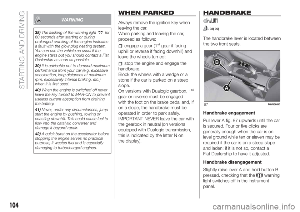
Pull lever A fig. 87 upwards until the car
is secured. Four or five clicks are
generally enough when the car is on
level ground while ten or eleven may be
required if the car is on a steep slope
and laden: if it is not so, contact a
Fiat Dealership to have it adjusted.
Handbrake disengagement
Slightly raise lever A and hold button B
pressed, checking that the
warning
light switches off in the instrument
panel.
87F0Y0601C
104
STARTING AND DRIVING
Page 114 of 248
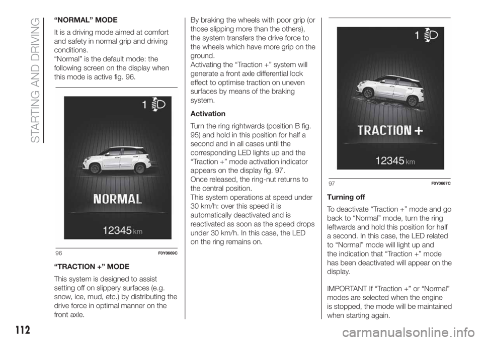
“NORMAL” MODE
It is a driving mode aimed at comfort
and safety in normal grip and driving
conditions.
“Normal” is the default mode: the
following screen on the display when
this mode is active fig. 96.
“TRACTION +” MODE
This system is designed to assist
setting off on slippery surfaces (e.g.
snow, ice, mud, etc.) by distributing the
drive force in optimal manner on the
front axle.By braking the wheels with poor grip (or
those slipping more than the others),
the system transfers the drive force to
the wheels which have more grip on the
ground.
Activating the “Traction +” system will
generate a front axle differential lock
effect to optimise traction on uneven
surfaces by means of the braking
system.
Activation
Turn the ring rightwards (position B fig.
95) and hold in this position for half a
second and in all cases until the
corresponding LED lights up and the
“Traction +” mode activation indicator
appears on the display fig. 97.
Once released, the ring-nut returns to
the central position.
This system operations at speed under
30 km/h: over this speed it is
automatically deactivated and is
reactivated as soon as the speed drops
under 30 km/h. In this case, the LED
on the ring remains on.Turning off
To deactivate “Traction +” mode and go
back to “Normal” mode, turn the ring
leftwards and hold this position for half
a second. In this case, the LED related
to “Normal” mode will light up and
the indication that “Traction +” mode
has been deactivated will appear on the
display.
IMPORTANT If “Traction +” or “Normal”
modes are selected when the engine
is stopped, the mode will be maintained
when starting again.
96F0Y0669C
97F0Y0667C
112
STARTING AND DRIVING
Page 121 of 248
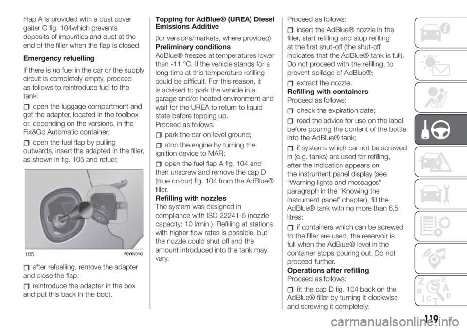
Flap A is provided with a dust cover
gaiter C fig. 104which prevents
deposits of impurities and dust at the
end of the filler when the flap is closed.
Emergency refuelling
If there is no fuel in the car or the supply
circuit is completely empty, proceed
as follows to reintroduce fuel to the
tank:
open the luggage compartment and
get the adapter, located in the toolbox
or, depending on the versions, in the
Fix&Go Automatic container;
open the fuel flap by pulling
outwards, insert the adapted in the filler,
as shown in fig. 105 and refuel;
after refuelling, remove the adapter
and close the flap;
reintroduce the adapter in the box
and put this back in the boot.Topping for AdBlue® (UREA) Diesel
Emissions Additive
(for versions/markets, where provided)
Preliminary conditions
AdBlue® freezes at temperatures lower
than -11 °C. If the vehicle stands for a
long time at this temperature refilling
could be difficult. For this reason, it
is advised to park the vehicle in a
garage and/or heated environment and
wait for the UREA to return to liquid
state before topping up.
Proceed as follows:
park the car on level ground;
stop the engine by turning the
ignition device to MAR;
open the fuel flap A fig. 104 and
then unscrew and remove the cap D
(blue colour) fig. 104 from the AdBlue®
filler.
Refilling with nozzles
The system was designed in
compliance with ISO 22241-5 (nozzle
capacity: 10 l/min.). Refilling at stations
with higher flow rates is possible, but
the nozzle could shut off and the
amount introduced into the tank may
vary.Proceed as follows:
insert the AdBlue® nozzle in the
filler, start refilling and stop refilling
at the first shut-off (the shut-off
indicates that the AdBlue® tank is full).
Do not proceed with the refilling, to
prevent spillage of AdBlue®;
extract the nozzle.
Refilling with containers
Proceed as follows:
check the expiration date;
read the advice for use on the label
before pouring the content of the bottle
into the AdBlue® tank;
if systems which cannot be screwed
in (e.g. tanks) are used for refilling,
after the indication appears on
the instrument panel display (see
“Warning lights and messages"
paragraph in the “Knowing the
instrument panel” chapter), fill the
AdBlue® tank with no more than 6.5
litres;
if containers which can be screwed
to the filler are used, the reservoir is
full when the AdBlue® level in the
container stops pouring out. Do not
proceed further.
Operations after refilling
Proceed as follows:
fit the cap D fig. 104 back on the
AdBlue® filler by turning it clockwise
and screwing it completely;
105F0Y0231C
119
Page 125 of 248
HAZARD WARNING
LIGHTS
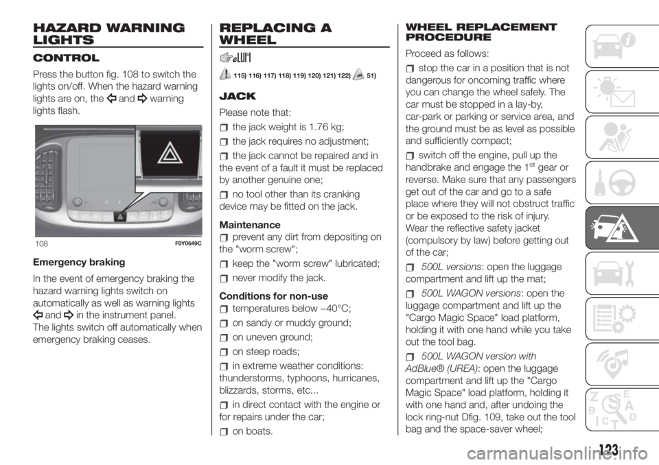
CONTROL
Press the button fig. 108 to switch the
lights on/off. When the hazard warning
lights are on, the
andwarning
lights flash.
Emergency braking
In the event of emergency braking the
hazard warning lights switch on
automatically as well as warning lights
andin the instrument panel.
The lights switch off automatically when
emergency braking ceases.
REPLACING A
WHEEL
115) 116) 117) 118) 119) 120) 121) 122)51)
JACK
Please note that:
the jack weight is 1.76 kg;
the jack requires no adjustment;
the jack cannot be repaired and in
the event of a fault it must be replaced
by another genuine one;
no tool other than its cranking
device may be fitted on the jack.
Maintenance
prevent any dirt from depositing on
the "worm screw";
keep the "worm screw" lubricated;
never modify the jack.
Conditions for non-use
temperatures below −40°C;
on sandy or muddy ground;
on uneven ground;
on steep roads;
in extreme weather conditions:
thunderstorms, typhoons, hurricanes,
blizzards, storms, etc...
in direct contact with the engine or
for repairs under the car;
on boats.WHEEL REPLACEMENT
PROCEDURE
Proceed as follows:
stop the car in a position that is not
dangerous for oncoming traffic where
you can change the wheel safely. The
car must be stopped in a lay-by,
car-park or parking or service area, and
the ground must be as level as possible
and sufficiently compact;
switch off the engine, pull up the
handbrake and engage the 1stgear or
reverse. Make sure that any passengers
get out of the car and go to a safe
place where they will not obstruct traffic
or be exposed to the risk of injury.
Wear the reflective safety jacket
(compulsory by law) before getting out
of the car;
500L versions: open the luggage
compartment and lift up the mat;
500L WAGON versions: open the
luggage compartment and lift up the
"Cargo Magic Space" load platform,
holding it with one hand while you take
out the tool bag.
500L WAGON version with
AdBlue® (UREA): open the luggage
compartment and lift up the "Cargo
Magic Space" load platform, holding it
with one hand and, after undoing the
lock ring-nut Dfig. 109, take out the tool
bag and the space-saver wheel;
108F0Y0649C
123
Page 126 of 248

500L versions: using the wrench A
fig. 109 located in the tool box, loosen
the locking device, take the tool box
B and place it close to the wheel to be
replaced. Then take the space-saver
wheel C;
500L WAGON versions: lift up the
tab A fig. 110 of the luggage
compartment mat, take the wrench B
from the tool bag and fit it onto the
device C. Turn the wrench B
anticlockwise to unscrew the
space-saver wheel fixing bolt so that it
can be lowered, and use the wrench
to drag the wheel out of the car;
500L WAGON versions: turn the
device D fig. 111 and release the
space-saver wheel from its fixing
support E;
take the spanner A fig. 112 and
loosen the fixing stud bolts by about
one turn. For versions with alloy rims,
shake the car to facilitate detachment
of the rim from the wheel hub;
take the chock from the tool bag
and open it out (see fig. 113);
position the chock behind the wheel
diagonally opposite the one to be
replaced to prevent the car from
moving when it is raised, then fit the
jack underneath the car, next to the
wheel to be replaced;
insert the wrench A fig. 114 to
extend the jack until the top of the jack
B fits correctly into the sidemember
C (next to the mark
on the
sidemember itself);
109F0Y0096C
110F0Y0355C
111F0Y0357C
112F0Y0093C
113F0Y0211C
124
IN AN EMERGENCY
Page 127 of 248
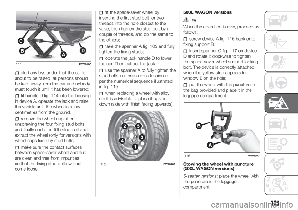
alert any bystander that the car is
about to be raised; all persons should
be kept away from the car and nobody
must touch it until it has been lowered;
fit handle D fig. 114 into the housing
in device A, operate the jack and raise
the vehicle until the wheel is a few
centimetres from the ground;
remove the wheel cap after
unscrewing the four fixing stud bolts
and finally undo the fifth stud bolt and
extract the wheel (only for versions with
wheel caps fixed by stud bolts);
make sure the contact surfaces
between space-saver wheel and hub
are clean and free from impurities
so that the fixing stud bolts will not
come loose;
fit the space-saver wheel by
inserting the first stud bolt for two
threads into the hole closest to the
valve, then tighten the stud bolt by a
couple of threads, and do the same to
the others;
take the spanner A fig. 109 and fully
tighten the fixing studs;
operate the jack handle D to lower
the car. Then extract the jack;
use the spanner A to fully tighten the
stud bolts in a criss-cross fashion as
per the numerical sequence illustrated
in fig. 115;
when replacing a wheel with alloy
rim it is advisable to place it upside
down (side with finish facing upwards).500L WAGON versions
123)
When the operation is over, proceed as
follows:
screw device A fig. 116 back onto
fixing support B;
insert spanner C fig. 117 on device
D and rotate it clockwise to tighten
the space-saver wheel support locking
bolt. The device is correctly attached
when the yellow strip appears in
window E on the hole;
put the wheel with the puncture in
the bag provided and place it in the
luggage compartment.
Stowing the wheel with puncture
(500L WAGON versions)
5-seater versions: place the wheel with
the puncture in the luggage
compartment.
114F0Y0014C
115F0Y0013C
116F0Y0360C
125
Page 129 of 248

116)The space-saver wheel (for
versions/markets where provided) is
specific to your car, do not use it on other
models, or use the space-saver wheel
of other models on your car. The
space-saver wheel must only be used in
the event of an emergency. Never use it for
more than strictly necessary and never
exceed 80 km/h. "Warning! For temporary
use only! 80km/h max! Replace with
standard wheel as soon as possible. Never
remove or cover the sticker on the
space-saver wheel. Never apply a wheel
cap on a space-saver wheel. The vehicle's
driving characteristics will be modified
with the space-saver wheel fitted. Avoid
violent acceleration and braking, abrupt
steering and fast cornering.
117)Alert other drivers that the car is
stationary in compliance with local
regulations: hazard warning lights, warning
triangle, etc. Any passengers on board
should leave the car, especially if it is
heavily laden. Passengers should stay
away from on-coming traffic while the
wheel is being changed. If you are on a
slope or uneven surface, place the wedge
provided under the wheel (see the
instructions on the next pages).118)The vehicle's driving characteristics
will be modified with the space-saver wheel
fitted. Avoid violent acceleration and
braking, abrupt steering and fast cornering.
The overall duration of the space-saver
wheel is of about 3000 km, after which the
relevant tyre must be replaced with another
one of the same type. Never install a
standard tyre on a rim that is designed for
use with a space-saver wheel. Have the
wheel repaired and refitted as soon as
possible. Using two or more space-saver
wheels at the same time is forbidden.
Do not grease the threads of the stud bolts
before fitting them: they might slip out.
119)The jack is a tool developed and
designed only for changing a wheel, if a
tyre gets punctured or damaged, on the
vehicle with which it is supplied or on other
vehicles of the same model. Any other
use, e.g. to jack up other vehicle models or
different things, is strictly prohibited. Never
use it to carry out maintenance or repairs
under the vehicle or to change summer/
winter wheels and vice versa: we advise
you to contact a Fiat Dealership. Never go
under the raised vehicle: use it only in
the positions indicated. Do not use the jack
for loads higher than the one shown on
its label. Never start the engine with vehicle
raised. If the vehicle is raised more than
necessary, everything can become more
unstable, with the risk of the vehicle
dropping violently. Thus, lift the car only as
needed in order to access the space-saver
spare wheel.120)The space-saver wheel cannot be
fitted with snow chains. If a front (drive) tyre
is punctured and chains are needed, use
a standard wheel from the rear axle and
install the space-saver wheel on the rear
axle. In this way, with two normal drive
wheels at the front axle, it is possible to use
snow chains.
121)When turning the jack handle make
sure that it can turn freely without scraping
your hand against the ground. The moving
components of the jack ("worm screw"
and joints) can also cause injuries: do not
touch them. If you come into contact
with lubricating grease, clean yourself
thoroughly.
122)Incorrectly fitting the wheel cap may
cause it to fall off when the car is in motion.
Never tamper with the inflation valve.
Never introduce tools of any kind between
rim and tyre. Check tyre and space-saver
wheel pressures regularly, complying
with the values given in the "Technical
specifications" chapter.
123)At the end of the operation of
raising/locking the space-saver wheel
device, the spanner must be extracted,
taking care NOT to turn it in the wrong
direction to facilitate the extraction of the
spanner itself, so as to prevent the
attachment device from being released and
the lack of safe restraint.
WARNING
51)Contact a Fiat Dealership as soon as
possible to have the correct tightening
of the wheel stud bolts checked.
127
Page 135 of 248

FRONT UPPER LIGHT
CLUSTER
This contains the bulbs for the direction
indicators and dipped headlights.
The bulbs are arranged as follows fig.
125:
A: direction indicators
B: dipped beam headlights
DIRECTION INDICATORS
To replace the bulb, proceed as follows:
remove cover A fig. 125;
turn bulb holder B fig. 126
anticlockwise, extract bulb C and
replace it;
refit the new bulb on the bulb holder,
making sure it is correctly locked;
refit the bulb holder in its housing
and turn it clockwise, until the locking
click is heard;
then refit the cover A fig. 125.DIPPED BEAM
HEADLIGHTS
To replace the bulb, proceed as follows:
remove cover B fig. 125;
remove the connector and bulb
holder C fig. 127 unit, releasing it
outwards;
remove bulb D from connector E
and replace it;
refit the new bulb on the connector,
making sure it is correctly locked;
refit the connector and bulb holder C
unit in its housing;
then refit the cover B fig. 125.
FRONT LOWER LIGHT
CLUSTER
This contains the bulbs for the main
beams and side lights/daytime running
lights (DRL).
The bulbs are arranged as follows fig.
128:
C: main beam headlights
D: side lights/daytime running lights
(DRL)
MAIN BEAM HEADLIGHTS
To replace the bulb, proceed as
follows:
steer the wheel completely inwards;
undo the screws A fig. 129 and
remove the flap B;
remove cover C fig. 128;
125F0Y0021C
126F0Y0022C
127F0Y0023C
128F0Y0499C
133