fuse FIAT 500L LIVING 2014 2.G Owners Manual
[x] Cancel search | Manufacturer: FIAT, Model Year: 2014, Model line: 500L LIVING, Model: FIAT 500L LIVING 2014 2.GPages: 420, PDF Size: 9.77 MB
Page 7 of 420
GETTING TO KNOW YOUR CAR
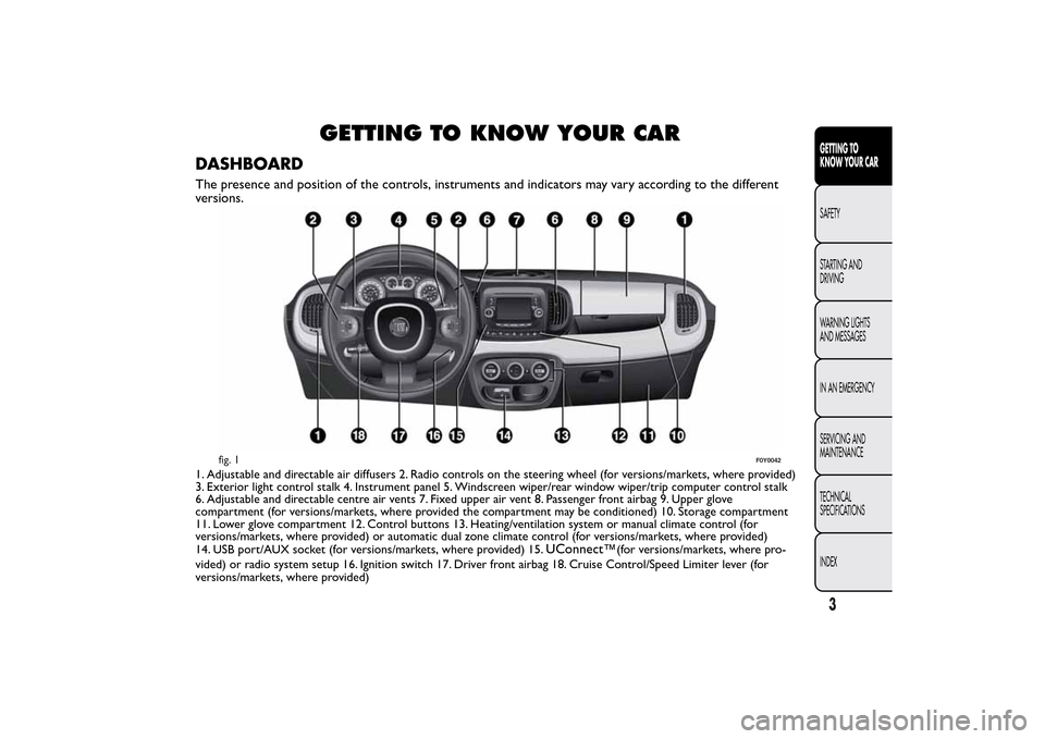
DASHBOARDThe presence and position of the controls, instruments and indicators may vary according to the different
versions.1. Adjustable and directable air diffusers 2. Radio controls on the steering wheel (for versions/markets, where provided)
3. Exterior light control stalk 4. Instrument panel 5. Windscreen wiper/rear window wiper/trip computer control stalk
6. Adjustable and directable centre air vents 7. Fixed upper air vent 8. Passenger front airbag 9. Upper glove
compartment (for versions/markets, where provided the compartment may be conditioned) 10. Storage compartment
11. Lower glove compartment 12. Control buttons 13. Heating/ventilation system or manual climate control (for
versions/markets, where provided) or automatic dual zone climate control (for versions/markets, where provided)
14. USB port/AUX socket (for versions/markets, where provided) 15.
UConnect
vided) or radio system setup 16. Ignition switch 17. Driver front airbag 18. Cruise Control/Speed Limiter lever (for
versions/markets, where provided)
fig. 1
F0Y0042
3GETTING TO
KNOW YOUR CARSAFETY
STARTING AND
DRIVING
WARNING LIGHTS
AND MESSAGES
IN AN EMERGENCY
SERVICING AND
MAINTENANCE
TECHNICAL
SPECIFICATIONS
INDEX
™ (for versions/markets, where pro-
Page 45 of 420
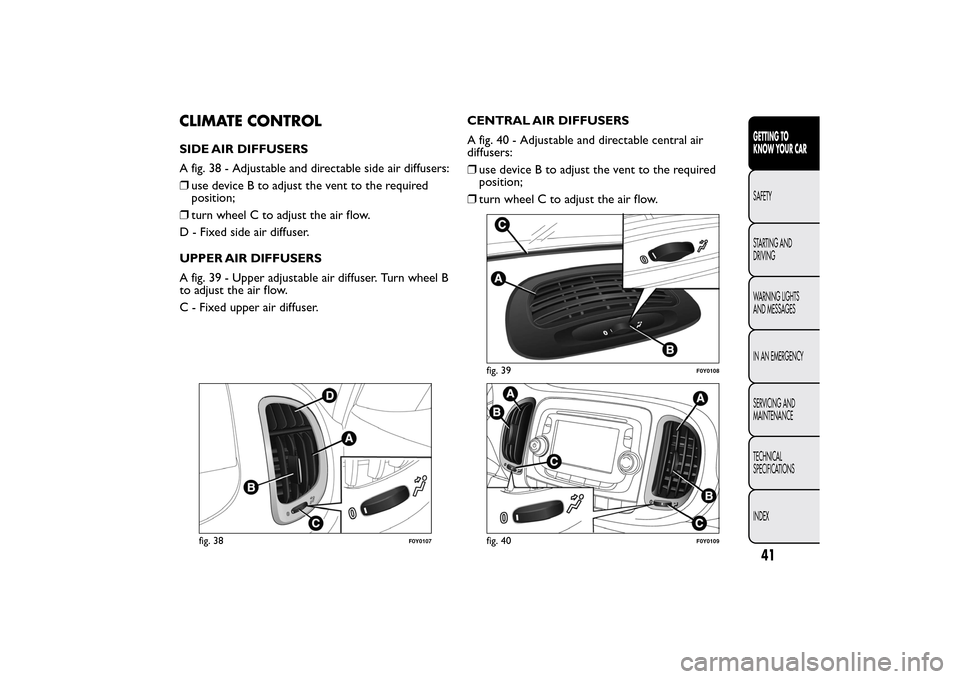
CLIMATE CONTROLSIDE AIR DIFFUSERS
A fig. 38 - Adjustable and directable side air diffusers:
❒use device B to adjust the vent to the required
position;
❒turn wheel C to adjust the air flow.
D - Fixed side air diffuser.
UPPER AIR DIFFUSERS
A fig. 39 - Upper adjustable air diffuser. Turn wheel B
to adjust the air flow.
C - Fixed upper air diffuser.CENTRAL AIR DIFFUSERS
A fig. 40 - Adjustable and directable central air
diffusers:
❒use device B to adjust the vent to the required
position;
❒turn wheel C to adjust the air flow.
fig. 38
F0Y0107
fig. 39
F0Y0108
fig. 40
F0Y0109
41GETTING TO
KNOW YOUR CARSAFETY
STARTING AND
DRIVING
WARNING LIGHTS
AND MESSAGES
IN AN EMERGENCY
SERVICING AND
MAINTENANCE
TECHNICAL
SPECIFICATIONS
INDEX
Page 46 of 420
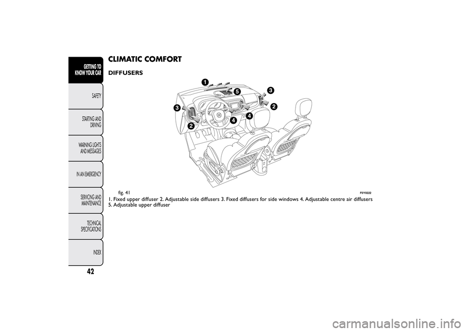
CLIMATIC COMFORTDIFFUSERS1. Fixed upper diffuser 2. Adjustable side diffusers 3. Fixed diffusers for side windows 4. Adjustable centre air diffusers
5. Adjustable upper diffuser
fig. 41
F0Y0222
42GETTING TO
KNOW YOUR CAR
SAFETY
STARTING AND
DRIVING
WARNING LIGHTS
AND MESSAGES
IN AN EMERGENCY
SERVICING AND
MAINTENANCE
TECHNICAL
SPECIFICATIONS
INDEX
Page 50 of 420
INTERNAL AIR RECIRCULATION
Press button B (
) so that the LED on the
button switches on. It is advisable to switch internal
air recirculation on while standing in traffic or in
tunnels to prevent the introduction of polluted air.
Do not use the function for a long time, particularly
if there are many passengers on board, to prevent
the windows from misting up.
IMPORTANT Internal air recirculation makes it
possible to reach the required heating or cooling
conditions more quickly depending on the mode
selected. Do not use the internal air recirculation
function on rainy/cold days as it would considerably
increase the possibility of the windows misting.AIR DISTRIBUTION SELECTION
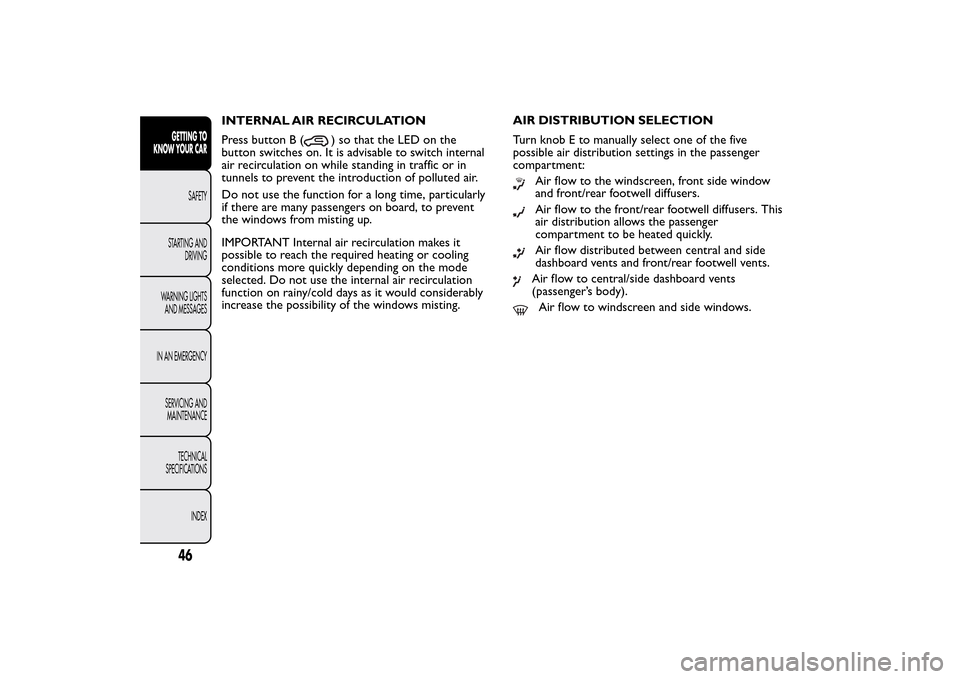
Turn knob E to manually select one of the five
possible air distribution settings in the passenger
compartment:
Air flow to the windscreen, front side window
and front/rear footwell diffusers.Air flow to the front/rear footwell diffusers. This
air distribution allows the passenger
compartment to be heated quickly.Air flow distributed between central and side
dashboard vents and front/rear footwell vents.Air flow to central/side dashboard vents
(passenger’s body).Air flow to windscreen and side windows.
46GETTING TO
KNOW YOUR CAR
SAFETY
STARTING AND
DRIVING
WARNING LIGHTS
AND MESSAGES
IN AN EMERGENCY
SERVICING AND
MAINTENANCE
TECHNICAL
SPECIFICATIONS
INDEX
Page 54 of 420
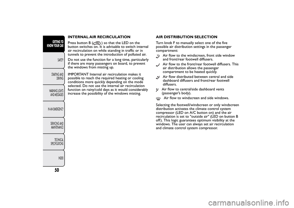
INTERNAL AIR RECIRCULATION
Press button B (
) so that the LED on the
button switches on. It is advisable to switch internal
air recirculation on while standing in traffic or in
tunnels to prevent the introduction of polluted air.
Do not use the function for a long time, particularly
if there are many passengers on board, to prevent
the windows from misting up.
IMPORTANT Internal air recirculation makes it
possible to reach the required heating or cooling
conditions more quickly depending on the mode
selected. Do not use the internal air recirculation
function on rainy/cold days as it would considerably
increase the possibility of the windows misting.AIR DISTRIBUTION SELECTION
Turn knob F to manually select one of the five
possible air distribution settings in the passenger
compartment:
Air flow to the windscreen, front side window
and front/rear footwell diffusers.Air flow to the front/rear footwell diffusers. This
air distribution allows the passenger
compartment to be heated quickly.Air flow distributed between central and side
dashboard diffusers and front/rear footwell
diffusers.Air flow to central/side dashboard vents
(passenger’s body).Air flow to windscreen and side windows.
Selecting the footwell/windscreen or only windscreen
distribution activates the climate control system
compressor (LED on A/C button on) and the air
recirculation is set to "outside air" (LED on button B
off ). This logic guarantees optimum visibility at the
windows. The user can always set air recirculation
and climate control system compressor.
50GETTING TO
KNOW YOUR CAR
SAFETY
STARTING AND
DRIVING
WARNING LIGHTS
AND MESSAGES
IN AN EMERGENCY
SERVICING AND
MAINTENANCE
TECHNICAL
SPECIFICATIONS
INDEX
Page 59 of 420
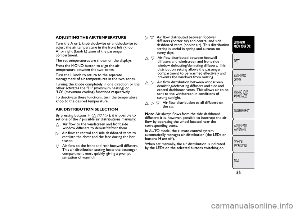
ADJUSTING THE AIR TEMPERATURE
Turn the A or L knob clockwise or anticlockwise to
adjust the air temperature in the front left (knob
A) or right (knob L) zone of the passenger
compartment.
The set temperatures are shown on the displays.
Press the MONO button to align the air
temperature between the two zones.
Turn the L knob to return to the separate
management of air temperatures in the two zones.
Turning the knobs completely in one direction or the
other activates the "HI" (maximum heating) or
"LO" (maximum cooling) functions respectively.
To deactivate these functions, turn the temperature
knob to the desired temperature.
AIR DISTRIBUTION SELECTION
By pressing buttons H (
/
/
), it is possible to
set one of the 7 possible air distributions manually:
Air flow to the windscreen and front side
window diffusers to demist/defrost them.Air flow at central and side dashboard vents to
ventilate the chest and the face during the hot
season.Air flow to the front and rear footwell diffusers.
This air distribution setting heats the passenger
compartment most quickly, giving a prompt
sensation of warmth.
Air flow distributed between footwell
diffusers (hotter air) and central and side
dashboard vents (cooler air). This distribution
setting is useful in spring and autumn on
sunny days.Air flow distributed between footwell
diffusers and windscreen and front side
window defrosting/demisting diffusers. This
distribution setting allows the passenger
compartment to be warmed effectively and
prevents the windows from misting.Air flow distribution between windscreen
demisting/defrosting diffusers and side and
central dashboard vents. This allows air to be
sent to the windscreen in conditions of
strong sunlight.
Air flow distribution to all diffusers on
the car.
NoteAir always flows from the side dashboard
diffusers: it is, however, possible to interrupt the air
flow by operating the wheel located near the
corresponding vents.
In AUTO mode, the climate control system
automatically manages air distribution (the LEDs on
buttons H are off ).
When set manually, the air distribution is indicated
by the LEDs on the selected buttons switching on.
55GETTING TO
KNOW YOUR CARSAFETY
STARTING AND
DRIVING
WARNING LIGHTS
AND MESSAGES
IN AN EMERGENCY
SERVICING AND
MAINTENANCE
TECHNICAL
SPECIFICATIONS
INDEX
Page 62 of 420
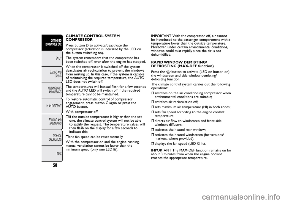
CLIMATE CONTROL SYSTEM
COMPRESSOR
Press button D to activate/deactivate the
compressor (activation is indicated by the LED on
the button switching on).
The system remembers that the compressor has
been switched off, even after the engine has stopped.
When the compressor is switched off the system
deactivates air recirculation to prevent the windows
from misting up. In this case, if the system is capable
of maintaining the required temperature, the AUTO
LED does not switch off.
The temperatures will instead flash for a few seconds
and the AUTO LED will switch off if the required
temperature cannot be maintained.
To restore automatic control of compressor
engagement, press button C again or press the
AUTO button.
With compressor off:
❒if the outside temperature is higher than the set
one, the climate control system will not be able
to satisfy the request. The temperature values will
then flash on the display for a few seconds to
indicate this;
❒the fan speed can be reset manually.
With the compressor on and the engine running,
manual ventilation cannot be lower than the
minimum speed (only one LED lit).IMPORTANT With the compressor off, air cannot
be introduced to the passenger compartment with a
temperature lower than the outside temperature.
Moreover, under certain environmental conditions,
windows could mist rapidly since the air is not
dehumidified.
RAPID WINDOW DEMISTING/
DEFROSTING (MAX-DEF function)
Press the
button to activate (LED on button on)
the windscreen and side window demisting/
defrosting function.
The climate control system carries out the following
operations:
❒switches on the air conditioning compressor when
environmental conditions are suitable;
❒switches air recirculation off;
❒sets maximum air temperature (HI) in both zones;
❒sets fan speed according to the engine coolant
temperature;
❒directs air flow to windscreen and front side
windows diffusers;
❒activates the heated rear window;
❒activates the heated windscreen (for versions/
markets, where provided);
❒displays the fan speed (LED G lit).
IMPORTANT The MAX-DEF function remains on for
about 3 minutes from when the engine coolant
reaches the appropriate temperature.
58GETTING TO
KNOW YOUR CAR
SAFETY
STARTING AND
DRIVING
WARNING LIGHTS
AND MESSAGES
IN AN EMERGENCY
SERVICING AND
MAINTENANCE
TECHNICAL
SPECIFICATIONS
INDEX
Page 94 of 420
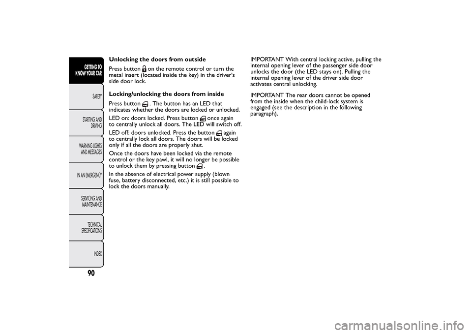
Unlocking the doors from outside
Press button
on the remote control or turn the
metal insert (located inside the key) in the driver's
side door lock.
Locking/unlocking the doors from inside
Press button. The button has an LED that
indicates whether the doors are locked or unlocked.
LED on: doors locked. Press button
once again
to centrally unlock all doors. The LED will switch off.
LED off: doors unlocked. Press the button
again
to centrally lock all doors. The doors will be locked
only if all the doors are properly shut.
Once the doors have been locked via the remote
control or the key pawl, it will no longer be possible
to unlock them by pressing button
.
In the absence of electrical power supply (blown
fuse, battery disconnected, etc.) it is still possible to
lock the doors manually.IMPORTANT With central locking active, pulling the
internal opening lever of the passenger side door
unlocks the door (the LED stays on). Pulling the
internal opening lever of the driver side door
activates central unlocking.
IMPORTANT The rear doors cannot be opened
from the inside when the child-lock system is
engaged (see the description in the following
paragraph).
90GETTING TO
KNOW YOUR CAR
SAFETY
STARTING AND
DRIVING
WARNING LIGHTS
AND MESSAGES
IN AN EMERGENCY
SERVICING AND
MAINTENANCE
TECHNICAL
SPECIFICATIONS
INDEX
Page 96 of 420
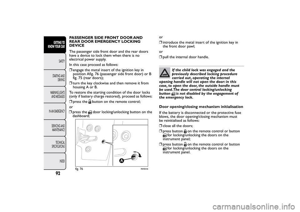
PASSENGER SIDE FRONT DOOR AND
REAR DOOR EMERGENCY LOCKING
DEVICE
The passenger side front door and the rear doors
have a device to lock them when there is no
electrical power supply.
In this case proceed as follows:
❒engage the metal insert of the ignition key in
position Afig. 76 (passenger side front door) or B
fig. 75 (rear doors);
❒turn the key clockwise and then remove it from
housing A or B.
To restore the starting condition of the door locks
(only if battery charge restored), proceed as follows:
❒press the
button on the remote control;
or
❒press thedoor locking/unlocking button on the
dashboard;or
❒introduce the metal insert of the ignition key in
the front door pawl;
or
❒pull the internal door handle.
If the child lock was engaged and the
previously described locking procedure
carried out , operating the internal
opening handle will not open the door: in this
case, to open the door, the outside handle must
be used.The door central locking/unlocking
button
is not disabled by the engagement of
the emergency lock.
Door opening/closing mechanism initialisation
If the battery is disconnected or the protective fuse
blows, the door opening/closing mechanism must
be reinitialised as follows:
❒close all the doors;
❒press button
on the remote control or button
for locking/unlocking the doors on the
instrument panel;
❒press button
on the remote control or button
for locking/unlocking the doors on the
instrument panel.
fig. 76
F0Y0110
92GETTING TO
KNOW YOUR CAR
SAFETY
STARTING AND
DRIVING
WARNING LIGHTS
AND MESSAGES
IN AN EMERGENCY
SERVICING AND
MAINTENANCE
TECHNICAL
SPECIFICATIONS
INDEX
Page 102 of 420
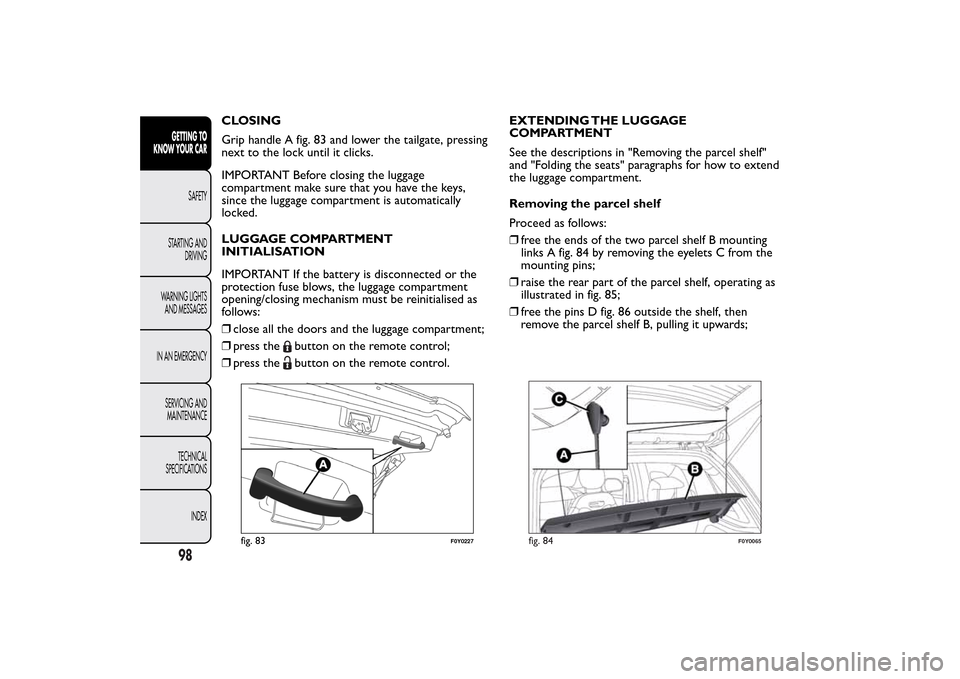
CLOSING
Grip handle A fig. 83 and lower the tailgate, pressing
next to the lock until it clicks.
IMPORTANT Before closing the luggage
compartment make sure that you have the keys,
since the luggage compartment is automatically
locked.
LUGGAGE COMPARTMENT
INITIALISATION
IMPORTANT If the battery is disconnected or the
protection fuse blows, the luggage compartment
opening/closing mechanism must be reinitialised as
follows:
❒close all the doors and the luggage compartment;
❒press the
button on the remote control;
❒press thebutton on the remote control.EXTENDING THE LUGGAGE
COMPARTMENT
See the descriptions in "Removing the parcel shelf"
and "Folding the seats" paragraphs for how to extend
the luggage compartment.
Removing the parcel shelf
Proceed as follows:
❒free the ends of the two parcel shelf B mounting
links A fig. 84 by removing the eyelets C from the
mounting pins;
❒raise the rear part of the parcel shelf, operating as
illustrated in fig. 85;
❒free the pins D fig. 86 outside the shelf, then
remove the parcel shelf B, pulling it upwards;
fig. 83
F0Y0227
fig. 84
F0Y0065
98GETTING TO
KNOW YOUR CAR
SAFETY
STARTING AND
DRIVING
WARNING LIGHTS
AND MESSAGES
IN AN EMERGENCY
SERVICING AND
MAINTENANCE
TECHNICAL
SPECIFICATIONS
INDEX