brake FIAT 500L LIVING 2015 2.G Owner's Manual
[x] Cancel search | Manufacturer: FIAT, Model Year: 2015, Model line: 500L LIVING, Model: FIAT 500L LIVING 2015 2.GPages: 224, PDF Size: 5.92 MB
Page 104 of 224
OPERATION WITH A
TRAILERSensor operation is deactivated
automatically when the trailer's electric
cable plug is fitted into the car's tow
hook socket.
The sensors are automatically
reactivated when the trailer's cable plug
is removed.IMPORTANT
INFORMATIONWhen parking, take the utmost care
over obstacles that may be above
or below the sensors.
Under certain circumstances, objects
close to the vehicle are not detected by
the system and could therefore cause
damage to the car or be damaged
themselves.
Some conditions may influence the
performance of the parking sensors:
❒the presence of ice, snow, mud
or think paint on the sensor surface
may cause reduced sensitivity of the
sensor itself and therefore reduce
the system performance.
❒mechanical interference (e.g. washing
the car, rain, strong wind, hail) may
cause the sensor to detect a
non-existent obstacle ("echo
interference");❒the presence of ultrasonic systems
(e.g. pneumatic brake systems of
trucks or pneumatic drills) near the car
could alter the signals sent by the
sensor;
❒the variation in sensor position,
caused by variation in ride (due
to suspension component wear),
changing tyres, overloaded car, or
tuning that lowers the car, for example,
may affect parking sensor system
performance.
WARNING
110)Parking and other dangerous
manoeuvres are, however, always the
driver’s responsibility. While carrying out
these manoeuvres, always make sure that
no people (especially children) or animals
are in the area concerned. The parking
sensors are an aid for the driver, but the
driver must never allow their attention
to lapse during potentially dangerous
manoeuvres, even those executed at low
speeds.
WARNING
59)The sensors must be free from mud,
dirt, snow or ice in order for the system to
operate correctly. Be careful not to scratch
or damage the sensors while cleaning
them. Avoid using dry, rough or hard
cloths. The sensors should be washed
using clean water with the addition of car
shampoo if necessary. When using special
washing equipment such as high pressure
jets or steam cleaning, clean the sensors
very quickly keeping the jet more than
10 cm away. Also, do not apply stickers to
the sensors.
102
STARTING AND DRIVING
9-1-2015 12:9 Pagina 102
Page 105 of 224
REAR VIEW CAMERA
111)
60)
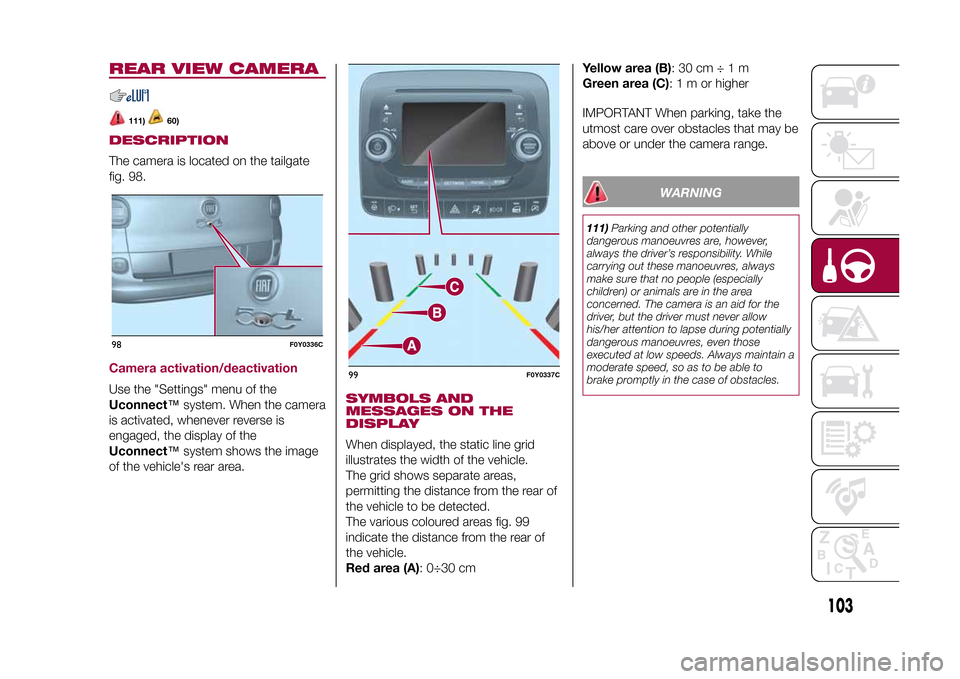
DESCRIPTIONThe camera is located on the tailgate
fig. 98.Camera activation/deactivationUse the "Settings" menu of the
Uconnect™system. When the camera
is activated, whenever reverse is
engaged, the display of the
Uconnect™system shows the image
of the vehicle's rear area.
SYMBOLS AND
MESSAGES ON THE
DISPLAYWhen displayed, the static line grid
illustrates the width of the vehicle.
The grid shows separate areas,
permitting the distance from the rear of
the vehicle to be detected.
The various coloured areas fig. 99
indicate the distance from the rear of
the vehicle.
Red area (A): 0÷30 cmYellow area (B):30cm÷1m
Green area (C):1morhigher
IMPORTANT When parking, take the
utmost care over obstacles that may be
above or under the camera range.
WARNING
111)Parking and other potentially
dangerous manoeuvres are, however,
always the driver’s responsibility. While
carrying out these manoeuvres, always
make sure that no people (especially
children) or animals are in the area
concerned. The camera is an aid for the
driver, but the driver must never allow
his/her attention to lapse during potentially
dangerous manoeuvres, even those
executed at low speeds. Always maintain a
moderate speed, so as to be able to
brake promptly in the case of obstacles.
98
F0Y0336C
99
F0Y0337C
103
9-1-2015 12:9 Pagina 103
Page 106 of 224
WARNING
60)It is extremely important, for correct
operation, that the camera is always kept
clean and free from mud, dirt, snow or ice.
Be careful not to scratch or damage the
camera while cleaning it. Avoid using
dry, rough or hard cloths. The camera
must be washed using clean water, with
the addition of car shampoo if necessary.
In washing stations which use steam or
high-pressure jets, clean the camera
quickly, keeping the nozzle more than 10
cm away. Do not apply stickers to the
camera.
TOWING TRAILERS
112) 113) 114)
INSTALLING A TOW
HOOKThe towing device should be fastened
to the body by specialised personnel
according to any additional and/or
integrative information supplied by the
Manufacturer of the device.
The towing device must meet current
regulations with reference to Directive
94/20/EC and subsequent
amendments.
For any version the towing device used
must be right for the towable weight
of the vehicle on which it is to be
installed.
For the electrical connection a standard
connector should be used which is
generally placed on a special bracket
normally fastened to the towing device,
and a special ECU for external trailer
light control must be installed on the
vehicle.
Seven or thirteen pin 12 V DC
connections should be used (CUNA/
UNI and ISO/DIN Standards). Follow
any instructions provided by the vehicle
manufacturer and/or the towing device
manufacturer.
IMPORTANTFor towing caravans or trailers the car
must be fitted with a type-approved
tow hook and an adequate electrical
system. Installation must be carried out
by a specialist.
Install any specific and/or additional
rear view mirrors as specified by the
Highway Code.
Remember that when towing a trailer,
steep hills are harder to climb, braking
distances increase and overtaking
takes longer depending on the overall
weight of the trail.
Engage a low gear when driving
downhill, rather than constantly using
the brake.
The weight of the trailer on the car's
tow hook will reduce the load capacity
of the car by the same amount. To
make sure that the maximum towable
weight is not exceeded (given in the car
registration document) account should
be taken of the fully laden trailer,
including accessories and luggage.
Respect the speed limits specific to
each country for vehicles towing
trailers. In any case, the top speed
must not exceed 100 km/h.
Any electric brake or other device
(winch etc.) should be powered directly
by the battery through a cable with a
cross-section of no less than 2.5 mm
2.
104
STARTING AND DRIVING
9-1-2015 12:9 Pagina 104
Page 107 of 224
In addition to the electrical branches,
the car's electrical system can be
connected only to the supply cable for
an electric brake and to the cable for an
internal trailer light, though not more
than 15 W. To connect, use the preset
control unit with a battery cable with
cross-section no less than 2.5 mm
2.
IMPORTANT The use of auxiliary loads
other than external lights (electric brake,
winch, etc.) must occur with engine
running.
IMPORTANT To install a tow hook
contact a Fiat Dealership.
WARNING
112)The ABS with which the vehicle is
equipped will not control the braking
system of the trailer. Take particular care
when travelling on slippery roads.
113)Never modify the braking system of
the vehicle to control the trailer brake. The
trailer braking system must be fully
independent of the vehicle’s hydraulic
system.
114)After fitting, fixing screw holes must
be sealed to prevent an exhaust gas inlet.
REFUELLING THE
VEHICLE
115) 116) 117)
61)
During refuelling, switch the engine off,
engage the handbrake, turn the ignition
key to STOP and do not smoke.PETROL ENGINESUse unleaded petrol only, with octane
number (RON) no lower than 95.DIESEL ENGINESOnly use Diesel for motor vehicles (EN
590 specification).
When using or parking the car for a
long time in the mountains or cold
areas, it is advisable to refuel using
locally available diesel. In this case, it is
also advisable to keep the tank over
50% full.REFUELLING
PROCEDURE
Diesel and petrol versionsProceed as follows:
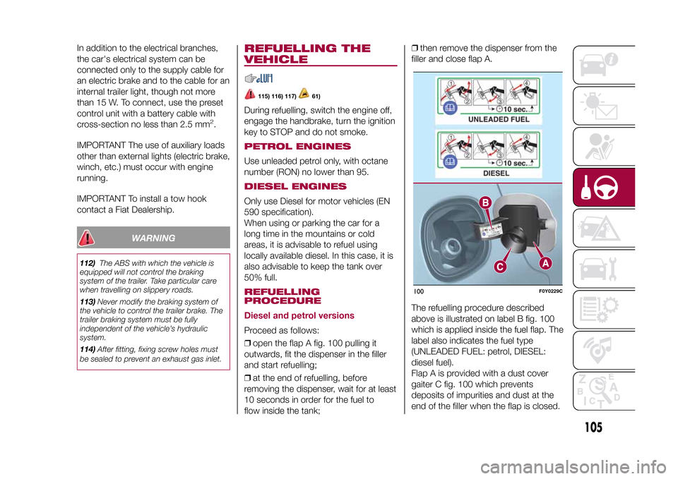
❒open the flap A fig. 100 pulling it
outwards, fit the dispenser in the filler
and start refuelling;
❒at the end of refuelling, before
removing the dispenser, wait for at least
10 seconds in order for the fuel to
flow inside the tank;❒then remove the dispenser from the
filler and close flap A.
The refuelling procedure described
above is illustrated on label B fig. 100
which is applied inside the fuel flap. The
label also indicates the fuel type
(UNLEADED FUEL: petrol, DIESEL:
diesel fuel).
Flap A is provided with a dust cover
gaiter C fig. 100 which prevents
deposits of impurities and dust at the
end of the filler when the flap is closed.
100
F0Y0229C
105
9-1-2015 12:9 Pagina 105
Page 111 of 224
HAZARD WARNING
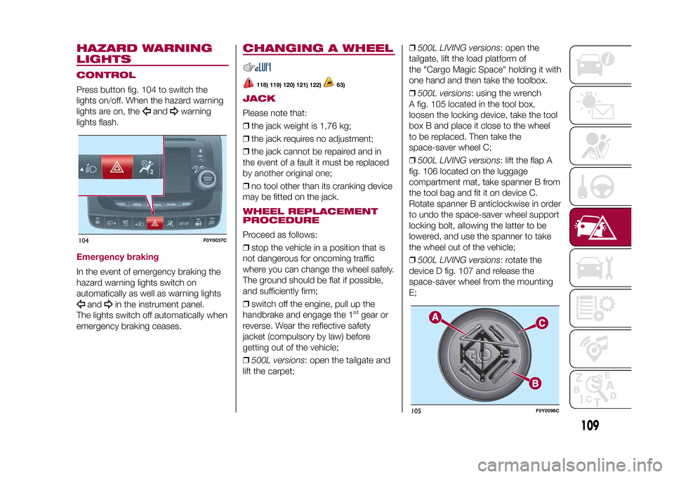
LIGHTSCONTROLPress button fig. 104 to switch the
lights on/off. When the hazard warning
lights are on, the
and
warning
lights flash.
Emergency brakingIn the event of emergency braking the
hazard warning lights switch on
automatically as well as warning lights
and
in the instrument panel.
The lights switch off automatically when
emergency braking ceases.
CHANGING A WHEEL
118) 119) 120) 121) 122)
63)
JACKPlease note that:
❒the jack weight is 1,76 kg;
❒the jack requires no adjustment;
❒the jack cannot be repaired and in
the event of a fault it must be replaced
by another original one;
❒no tool other than its cranking device
may be fitted on the jack.WHEEL REPLACEMENT
PROCEDUREProceed as follows:
❒stop the vehicle in a position that is
not dangerous for oncoming traffic
where you can change the wheel safely.
The ground should be flat if possible,
and sufficiently firm;
❒switch off the engine, pull up the
handbrake and engage the 1
stgear or
reverse. Wear the reflective safety
jacket (compulsory by law) before
getting out of the vehicle;
❒500L versions: open the tailgate and
lift the carpet;❒500L LIVING versions: open the
tailgate, lift the load platform of
the "Cargo Magic Space" holding it with
one hand and then take the toolbox.
❒500L versions: using the wrench
A fig. 105 located in the tool box,
loosen the locking device, take the tool
box B and place it close to the wheel
to be replaced. Then take the
space-saver wheel C;
❒500L LIVING versions: lift the flap A
fig. 106 located on the luggage
compartment mat, take spanner B from
the tool bag and fit it on device C.
Rotate spanner B anticlockwise in order
to undo the space-saver wheel support
locking bolt, allowing the latter to be
lowered, and use the spanner to take
the wheel out of the vehicle;
❒500L LIVING versions: rotate the
device D fig. 107 and release the
space-saver wheel from the mounting
E;
104
F0Y0037C
105
F0Y0096C
109
9-1-2015 12:9 Pagina 109
Page 116 of 224
❒instruction booklet to be used for
prompt and correct use of the kit and
then to be handed to the personnel
charged with handling the treated tyre;
❒a pair of protective gloves located
in the side compartment of the
compressor;
❒adapters for inflating different
elements.
IMPORTANT The sealing fluid is
effective with external temperatures of
between –20°C and +50°C. The sealing
fluid has an expiry date.INFLATION PROCEDUREProceed as follows:
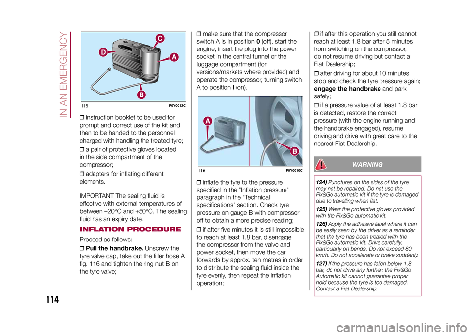
❒Pull the handbrake.Unscrew the
tyre valve cap, take out the filler hose A
fig. 116 and tighten the ring nut B on
the tyre valve;❒make sure that the compressor
switch A is in position0(off), start the
engine, insert the plug into the power
socket in the central tunnel or the
luggage compartment (for
versions/markets where provided) and
operate the compressor, turning switch
A to positionI(on).
❒inflate the tyre to the pressure
specified in the "Inflation pressure"
paragraph in the "Technical
specifications" section. Check tyre
pressure on gauge B with compressor
off to obtain a more precise reading;
❒if after five minutes it is still impossible
to reach at least 1.8 bar, disengage
the compressor from the valve and
power socket, then move the car
forwards by approx. ten metres in order
to distribute the sealing fluid inside the
tyre evenly, then repeat the inflation
operation;❒if after this operation you still cannot
reach at least 1.8 bar after 5 minutes
from switching on the compressor,
do not resume driving but contact a
Fiat Dealership;
❒after driving for about 10 minutes
stop and check the tyre pressure again;
engage the handbrakeand park
safely;
❒if a pressure value of at least 1.8 bar
is detected, restore the correct
pressure (with the engine running and
the handbrake engaged), resume
driving and drive with great care to the
nearest Fiat Dealership.
WARNING
124)Punctures on the sides of the tyre
may not be repaired. Do not use the
Fix&Go automatic kit if the tyre is damaged
due to travelling when flat.
125)Wear the protective gloves provided
with the Fix&Go automatic kit.
126)Apply the adhesive label where it can
be easily seen by the driver as a reminder
that the tyre has been treated with the
Fix&Go automatic kit. Drive carefully,
particularly on bends. Do not exceed 80
km/h. Do not accelerate or brake suddenly.
127)If the pressure has fallen below 1.8
bar, do not drive any further: the Fix&Go
Automatic kit cannot guarantee proper
hold because the tyre is too damaged.
Contact a Fiat Dealership.
115
F0Y0012C
116
F0Y0010C
114
IN AN EMERGENCY
9-1-2015 12:9 Pagina 114
Page 119 of 224
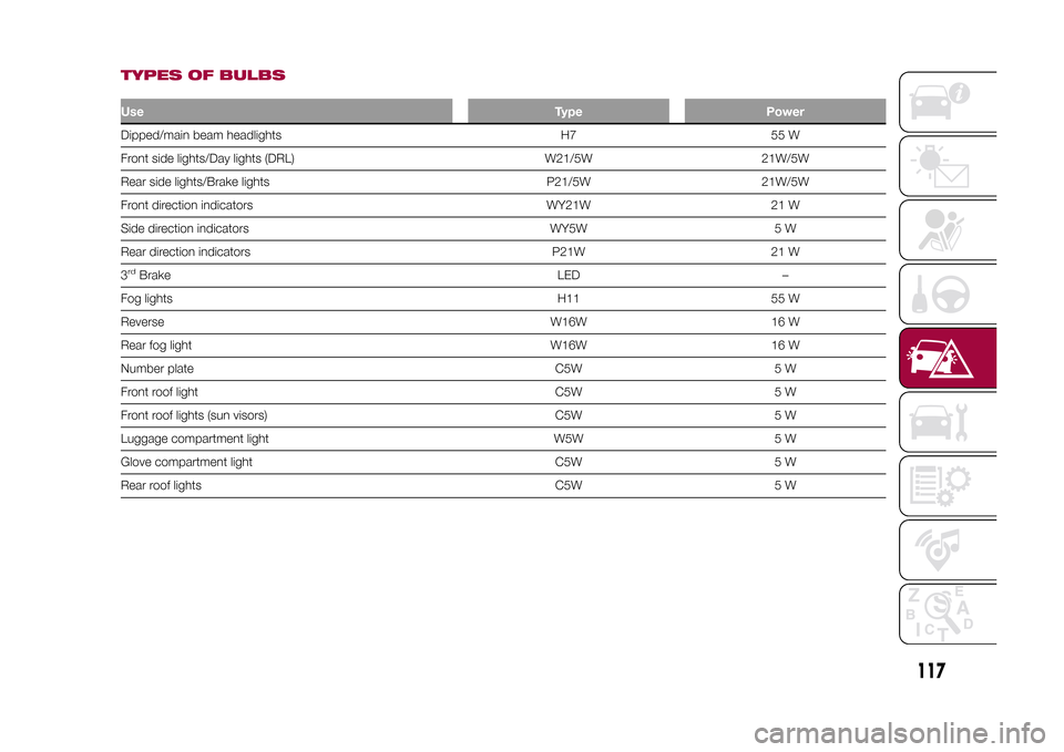
TYPES OF BULBSUseType PowerDipped/main beam headlights H7 55 W
Front side lights/Day lights (DRL) W21/5W 21W/5W
Rear side lights/Brake lights P21/5W 21W/5W
Front direction indicators WY21W 21 W
Side direction indicators WY5W 5 W
Rear direction indicators P21W 21 W
3rdBrake LED –
Fog lights H11 55 W
Reverse W16W 16 W
Rear fog light W16W 16 W
Number plate C5W 5 W
Front roof light C5W 5 W
Front roof lights (sun visors) C5W 5 W
Luggage compartment light W5W 5 W
Glove compartment light C5W 5 W
Rear roof lights C5W 5 W
117
9-1-2015 12:9 Pagina 117
Page 122 of 224
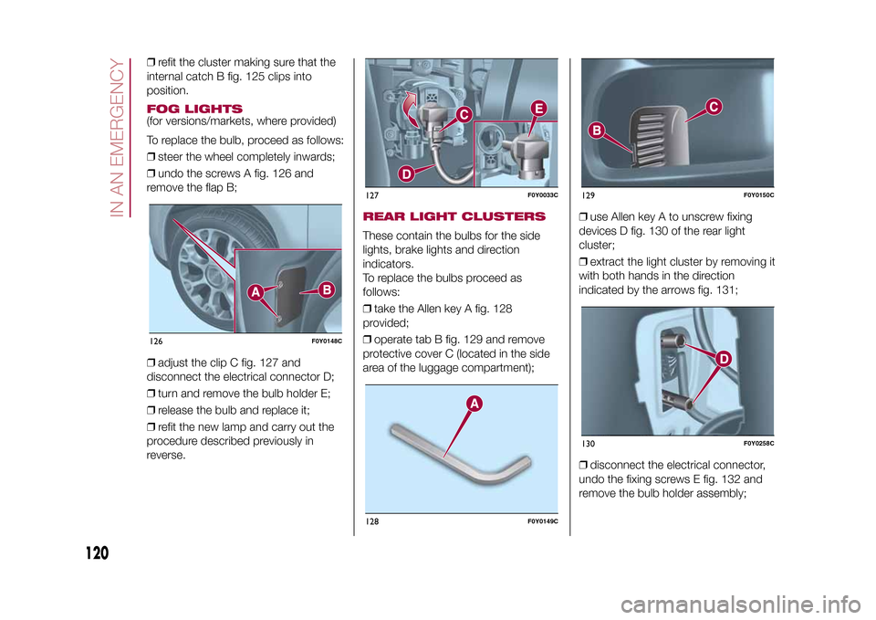
❒refit the cluster making sure that the
internal catch B fig. 125 clips into
position.FOG LIGHTS(for versions/markets, where provided)
To replace the bulb, proceed as follows:
❒steer the wheel completely inwards;
❒undo the screws A fig. 126 and
remove the flap B;
❒adjust the clip C fig. 127 and
disconnect the electrical connector D;
❒turn and remove the bulb holder E;
❒release the bulb and replace it;
❒refit the new lamp and carry out the
procedure described previously in
reverse.
REAR LIGHT CLUSTERSThese contain the bulbs for the side
lights, brake lights and direction
indicators.
To replace the bulbs proceed as
follows:
❒take the Allen key A fig. 128
provided;
❒operate tab B fig. 129 and remove
protective cover C (located in the side
area of the luggage compartment);❒use Allen key A to unscrew fixing
devices D fig. 130 of the rear light
cluster;
❒extract the light cluster by removing it
with both hands in the direction
indicated by the arrows fig. 131;
❒disconnect the electrical connector,
undo the fixing screws E fig. 132 and
remove the bulb holder assembly;
126
F0Y0148C
127
F0Y0033C
128
F0Y0149C
129
F0Y0150C
130
F0Y0258C
120
IN AN EMERGENCY
9-1-2015 12:9 Pagina 120
Page 123 of 224
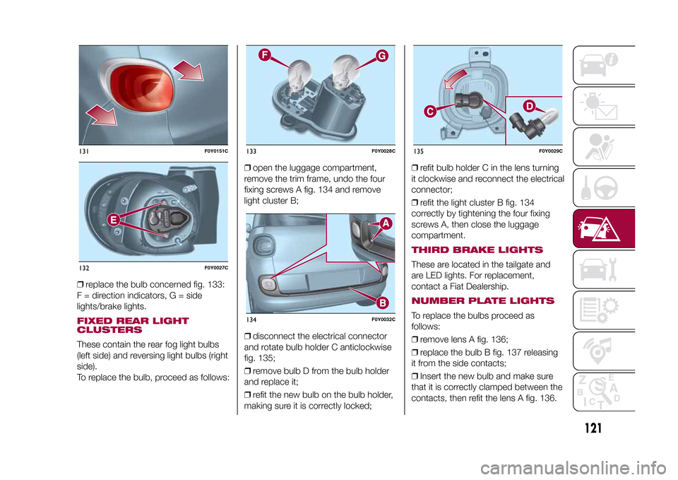
❒replace the bulb concerned fig. 133:
F = direction indicators, G = side
lights/brake lights.FIXED REAR LIGHT
CLUSTERSThese contain the rear fog light bulbs
(left side) and reversing light bulbs (right
side).
To replace the bulb, proceed as follows:❒open the luggage compartment,
remove the trim frame, undo the four
fixing screws A fig. 134 and remove
light cluster B;
❒disconnect the electrical connector
and rotate bulb holder C anticlockwise
fig. 135;
❒remove bulb D from the bulb holder
and replace it;
❒refit the new bulb on the bulb holder,
making sure it is correctly locked;❒refit bulb holder C in the lens turning
it clockwise and reconnect the electrical
connector;
❒refit the light cluster B fig. 134
correctly by tightening the four fixing
screws A, then close the luggage
compartment.
THIRD BRAKE LIGHTSThese are located in the tailgate and
are LED lights. For replacement,
contact a Fiat Dealership.NUMBER PLATE LIGHTSTo replace the bulbs proceed as
follows:
❒remove lens A fig. 136;
❒replace the bulb B fig. 137 releasing
it from the side contacts;
❒Insert the new bulb and make sure
that it is correctly clamped between the
contacts, then refit the lens A fig. 136.
131
F0Y0151C
132
F0Y0027C
133
F0Y0028C
134
F0Y0032C
135
F0Y0029C
121
9-1-2015 12:9 Pagina 121
Page 130 of 224
JUMP STARTINGIf the battery is flat, a jump starting can
be performed using the battery and
the cables of another vehicle, or using a
booster battery.IMPORTANTWhen a booster battery is used, comply
with the utilisation and precaution
instructions specified by the producer.
Do not use the booster battery or
any other source of external supply with
a voltage above 12 V: the battery, the
starter, the alternator and the electrical
system of the vehicle could be
damaged.
Do not attempt jump starting if the
battery is frozen. The battery could
break and explode!PREPARATION TO JUMP
STARTING
140) 141) 142)
68)
IMPORTANT The positive terminal (+) of
the battery is shielded by a protective
cover. Lift the cover to access the
positive terminal.
Proceed as follows:
❒engage the handbrake, move the
Dualogic gear lever to P (Park) or,
for versions with manual gearbox, to
neutral and bring the ignition key to
STOP;❒switch off all the other electrical
devices in the vehicle;
❒if another vehicle is ready for jump
starting, park the vehicle within the
reach of the cables to be used for
starting, operate the handbrake and
make sure that the ignition is
deactivated.
IMPORTANT Avoid contact between
the two vehicles since this could cause
a connection to earth and may result
in serious injury to any people nearby.
PROCEDURE FOR JUMP
STARTINGIMPORTANT If the procedure below is
carried out incorrectly, it can cause
severe injury to people or damage the
recharging system of one or both
vehicles. Carefully follow the
instructions given below.Cable connectionProceed as follows to carry out a jump
starting:
❒connect one end of the cable used
for positive (+) to the positive terminal
(+) of the vehicle with flat battery;
❒connect the other end of the cable
used for positive (+) to the positive
terminal (+) of the auxiliary battery;❒connect one end of the cable used
for negative (–) to the negative terminal
(–) of the auxiliary battery;
❒connect the other end of the cable
used for negative (–) to an engine earth
(the visible metal part of the vehicle
engine with flat battery) away from the
battery and the fuel injection system;
❒start the vehicle engine with the
auxiliary battery, let it run for a
few minutes at idling. Start the engine
of the vehicle with flat battery.
Cable disconnectionOnce the engine has been started,
remove the cables proceeding as
follows:
❒disconnect the end of the cable used
for negative (–) from the engine earth
of the vehicle with flat battery;
❒disconnect the other end of the cable
used for negative (–) from the negative
terminal (–) of the auxiliary battery;
❒disconnect the end of the cable used
for positive (+) from the positive terminal
(+) of the auxiliary battery;
❒disconnect one end of the cable
used for positive (+) from the positive
terminal (+) of the vehicle with flat
battery.
128
IN AN EMERGENCY
9-1-2015 12:9 Pagina 128