warning light FIAT 500L LIVING 2015 2.G Service Manual
[x] Cancel search | Manufacturer: FIAT, Model Year: 2015, Model line: 500L LIVING, Model: FIAT 500L LIVING 2015 2.GPages: 224, PDF Size: 5.92 MB
Page 98 of 224
WARNING
104)Depress the clutch pedal fully to
change gear correctly. Therefore, the floor
area underneath the pedal unit must not
be obstructed in any way. Ensure that the
floor mat is always laid flat and does not
interfere with use of the pedals.
WARNING
56)Do not drive with your hand resting on
the gear lever as the force exerted, even
if slight, could lead over time to premature
wear of the gearbox internal components.
USING THE
DUALOGIC
GEARBOX(for versions/markets, where provided)
105)
57)
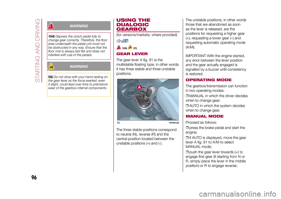
GEAR LEVERThe gear lever A fig. 91 is the
multistable floating type, in other words
it has three stable and three unstable
positions.
The three stable positions correspond
to neutral (N), reverse (R) and the
central position located between the
unstable positions (+) and (-).The unstable positions, in other words
those that are abandoned as soon
as the lever is released, are the
positions for requesting a higher gear
(+), requesting a lower gear (–) and
requesting automatic operating mode
(A/M).
IMPORTANT With the engine started,
any error between the lever position
and the gear actually engaged is
signalled by a buzzer until consistency
is restored.
OPERATING MODEThe gearbox/transmission can function
in two operating modes:
❒MANUAL in which the driver decides
when to change gear;
❒AUTO in which the system decides
when to change gear.MANUAL MODEProceed as follows:
❒press the brake pedal and start the
engine;
❒if AUTO is displayed, move the gear
lever A fig. 91 to A/M to select
MANUAL mode;
❒push the gear lever towards (+) to
engage first gear (if starting from N or
R, simply place the lever in the middle
position) or R to engage reverse;
91
F0Y0313C
96
STARTING AND DRIVING
9-1-2015 12:9 Pagina 96
Page 103 of 224
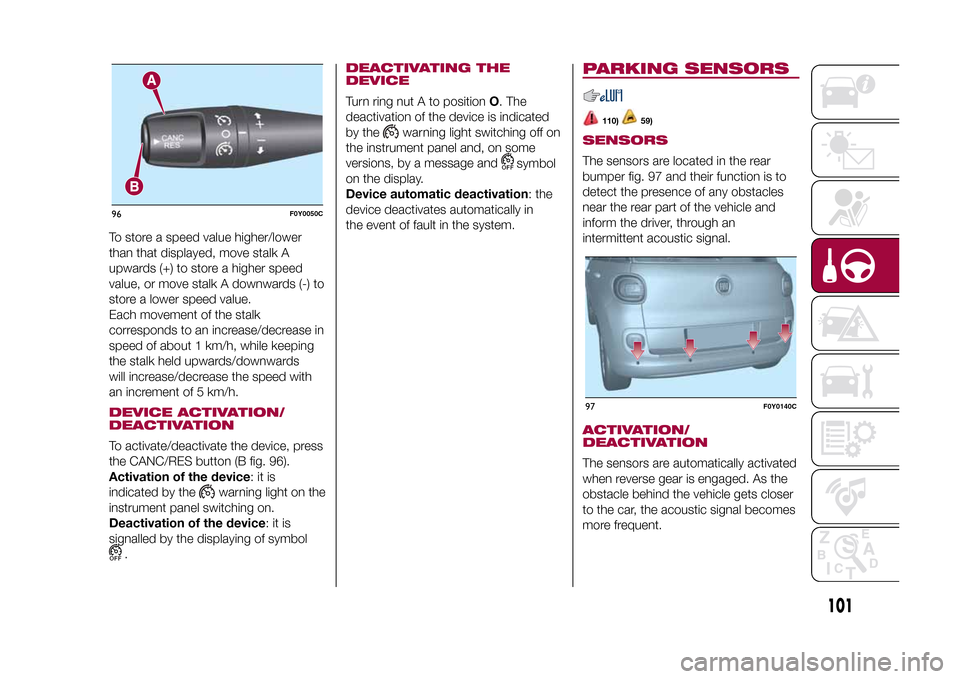
To store a speed value higher/lower
than that displayed, move stalk A
upwards (+) to store a higher speed
value, or move stalk A downwards (-) to
store a lower speed value.
Each movement of the stalk
corresponds to an increase/decrease in
speed of about 1 km/h, while keeping
the stalk held upwards/downwards
will increase/decrease the speed with
an increment of 5 km/h.DEVICE ACTIVATION/
DEACTIVATIONTo activate/deactivate the device, press
the CANC/RES button (B fig. 96).
Activation of the device:itis
indicated by the
warning light on the
instrument panel switching on.
Deactivation of the device:itis
signalled by the displaying of symbol
.
DEACTIVATING THE
DEVICETurn ring nut A to positionO. The
deactivation of the device is indicated
by the
warning light switching off on
the instrument panel and, on some
versions, by a message and
symbol
on the display.
Device automatic deactivation: the
device deactivates automatically in
the event of fault in the system.
PARKING SENSORS
110)
59)
SENSORSThe sensors are located in the rear
bumper fig. 97 and their function is to
detect the presence of any obstacles
near the rear part of the vehicle and
inform the driver, through an
intermittent acoustic signal.ACTIVATION/
DEACTIVATIONThe sensors are automatically activated
when reverse gear is engaged. As the
obstacle behind the vehicle gets closer
to the car, the acoustic signal becomes
more frequent.
96
F0Y0050C
97
F0Y0140C
101
9-1-2015 12:9 Pagina 101
Page 106 of 224
WARNING
60)It is extremely important, for correct
operation, that the camera is always kept
clean and free from mud, dirt, snow or ice.
Be careful not to scratch or damage the
camera while cleaning it. Avoid using
dry, rough or hard cloths. The camera
must be washed using clean water, with
the addition of car shampoo if necessary.
In washing stations which use steam or
high-pressure jets, clean the camera
quickly, keeping the nozzle more than 10
cm away. Do not apply stickers to the
camera.
TOWING TRAILERS
112) 113) 114)
INSTALLING A TOW
HOOKThe towing device should be fastened
to the body by specialised personnel
according to any additional and/or
integrative information supplied by the
Manufacturer of the device.
The towing device must meet current
regulations with reference to Directive
94/20/EC and subsequent
amendments.
For any version the towing device used
must be right for the towable weight
of the vehicle on which it is to be
installed.
For the electrical connection a standard
connector should be used which is
generally placed on a special bracket
normally fastened to the towing device,
and a special ECU for external trailer
light control must be installed on the
vehicle.
Seven or thirteen pin 12 V DC
connections should be used (CUNA/
UNI and ISO/DIN Standards). Follow
any instructions provided by the vehicle
manufacturer and/or the towing device
manufacturer.
IMPORTANTFor towing caravans or trailers the car
must be fitted with a type-approved
tow hook and an adequate electrical
system. Installation must be carried out
by a specialist.
Install any specific and/or additional
rear view mirrors as specified by the
Highway Code.
Remember that when towing a trailer,
steep hills are harder to climb, braking
distances increase and overtaking
takes longer depending on the overall
weight of the trail.
Engage a low gear when driving
downhill, rather than constantly using
the brake.
The weight of the trailer on the car's
tow hook will reduce the load capacity
of the car by the same amount. To
make sure that the maximum towable
weight is not exceeded (given in the car
registration document) account should
be taken of the fully laden trailer,
including accessories and luggage.
Respect the speed limits specific to
each country for vehicles towing
trailers. In any case, the top speed
must not exceed 100 km/h.
Any electric brake or other device
(winch etc.) should be powered directly
by the battery through a cable with a
cross-section of no less than 2.5 mm
2.
104
STARTING AND DRIVING
9-1-2015 12:9 Pagina 104
Page 107 of 224
In addition to the electrical branches,
the car's electrical system can be
connected only to the supply cable for
an electric brake and to the cable for an
internal trailer light, though not more
than 15 W. To connect, use the preset
control unit with a battery cable with
cross-section no less than 2.5 mm
2.
IMPORTANT The use of auxiliary loads
other than external lights (electric brake,
winch, etc.) must occur with engine
running.
IMPORTANT To install a tow hook
contact a Fiat Dealership.
WARNING
112)The ABS with which the vehicle is
equipped will not control the braking
system of the trailer. Take particular care
when travelling on slippery roads.
113)Never modify the braking system of
the vehicle to control the trailer brake. The
trailer braking system must be fully
independent of the vehicle’s hydraulic
system.
114)After fitting, fixing screw holes must
be sealed to prevent an exhaust gas inlet.
REFUELLING THE
VEHICLE
115) 116) 117)
61)
During refuelling, switch the engine off,
engage the handbrake, turn the ignition
key to STOP and do not smoke.PETROL ENGINESUse unleaded petrol only, with octane
number (RON) no lower than 95.DIESEL ENGINESOnly use Diesel for motor vehicles (EN
590 specification).
When using or parking the car for a
long time in the mountains or cold
areas, it is advisable to refuel using
locally available diesel. In this case, it is
also advisable to keep the tank over
50% full.REFUELLING
PROCEDURE
Diesel and petrol versionsProceed as follows:
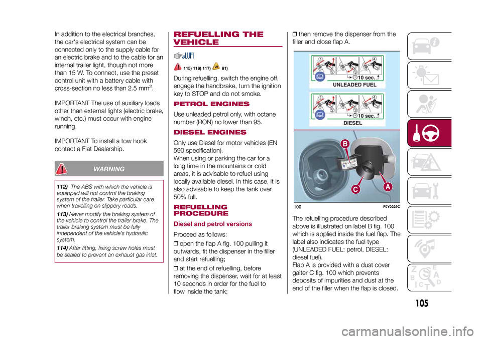
❒open the flap A fig. 100 pulling it
outwards, fit the dispenser in the filler
and start refuelling;
❒at the end of refuelling, before
removing the dispenser, wait for at least
10 seconds in order for the fuel to
flow inside the tank;❒then remove the dispenser from the
filler and close flap A.
The refuelling procedure described
above is illustrated on label B fig. 100
which is applied inside the fuel flap. The
label also indicates the fuel type
(UNLEADED FUEL: petrol, DIESEL:
diesel fuel).
Flap A is provided with a dust cover
gaiter C fig. 100 which prevents
deposits of impurities and dust at the
end of the filler when the flap is closed.
100
F0Y0229C
105
9-1-2015 12:9 Pagina 105
Page 110 of 224

IN AN EMERGENCY
A punctured tyre or a burnt-out bulb?
At times, a problem may interfere
with our journey.
The pages on emergencies can help
you to deal with critical situations
independently and with calm.
In an emergency we recommend that
you call the freephone number found in
the Warranty Booklet.
It is also possible to call the national or
international universal freephone
number to search for the nearest
Dealership.HAZARD WARNING LIGHTS...........109
CHANGING A WHEEL ....................109
"FIX&GO AUTOMATIC" KIT .............113
REPLACING A BULB ......................115
REPLACING FUSES........................122
JUMP STARTING ............................128
FUEL CUT-OFF SYSTEM ................129
TOWING THE VEHICLE ..................130
108
IN AN EMERGENCY
9-1-2015 12:9 Pagina 108
Page 111 of 224
HAZARD WARNING
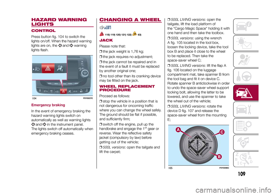
LIGHTSCONTROLPress button fig. 104 to switch the
lights on/off. When the hazard warning
lights are on, the
and
warning
lights flash.
Emergency brakingIn the event of emergency braking the
hazard warning lights switch on
automatically as well as warning lights
and
in the instrument panel.
The lights switch off automatically when
emergency braking ceases.
CHANGING A WHEEL
118) 119) 120) 121) 122)
63)
JACKPlease note that:
❒the jack weight is 1,76 kg;
❒the jack requires no adjustment;
❒the jack cannot be repaired and in
the event of a fault it must be replaced
by another original one;
❒no tool other than its cranking device
may be fitted on the jack.WHEEL REPLACEMENT
PROCEDUREProceed as follows:
❒stop the vehicle in a position that is
not dangerous for oncoming traffic
where you can change the wheel safely.
The ground should be flat if possible,
and sufficiently firm;
❒switch off the engine, pull up the
handbrake and engage the 1
stgear or
reverse. Wear the reflective safety
jacket (compulsory by law) before
getting out of the vehicle;
❒500L versions: open the tailgate and
lift the carpet;❒500L LIVING versions: open the
tailgate, lift the load platform of
the "Cargo Magic Space" holding it with
one hand and then take the toolbox.
❒500L versions: using the wrench
A fig. 105 located in the tool box,
loosen the locking device, take the tool
box B and place it close to the wheel
to be replaced. Then take the
space-saver wheel C;
❒500L LIVING versions: lift the flap A
fig. 106 located on the luggage
compartment mat, take spanner B from
the tool bag and fit it on device C.
Rotate spanner B anticlockwise in order
to undo the space-saver wheel support
locking bolt, allowing the latter to be
lowered, and use the spanner to take
the wheel out of the vehicle;
❒500L LIVING versions: rotate the
device D fig. 107 and release the
space-saver wheel from the mounting
E;
104
F0Y0037C
105
F0Y0096C
109
9-1-2015 12:9 Pagina 109
Page 114 of 224
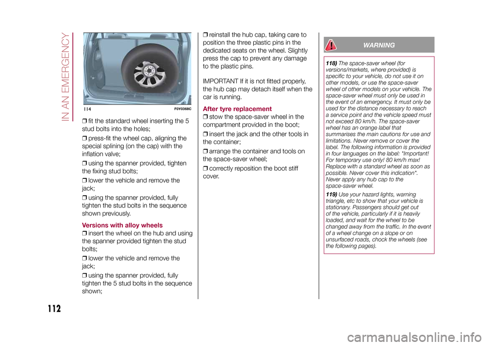
❒fit the standard wheel inserting the 5
stud bolts into the holes;
❒press-fit the wheel cap, aligning the
special splining (on the cap) with the
inflation valve;
❒using the spanner provided, tighten
the fixing stud bolts;
❒lower the vehicle and remove the
jack;
❒using the spanner provided, fully
tighten the stud bolts in the sequence
shown previously.Versions with alloy wheels❒insert the wheel on the hub and using
the spanner provided tighten the stud
bolts;
❒lower the vehicle and remove the
jack;
❒using the spanner provided, fully
tighten the 5 stud bolts in the sequence
shown;❒reinstall the hub cap, taking care to
position the three plastic pins in the
dedicated seats on the wheel. Slightly
press the cap to prevent any damage
to the plastic pins.
IMPORTANT If it is not fitted properly,
the hub cap may detach itself when the
car is running.
After tyre replacement❒stow the space-saver wheel in the
compartment provided in the boot;
❒insert the jack and the other tools in
the container;
❒arrange the container and tools on
the space-saver wheel;
❒correctly reposition the boot stiff
cover.
WARNING
118)The space-saver wheel (for
versions/markets, where provided) is
specific to your vehicle, do not use it on
other models, or use the space-saver
wheel of other models on your vehicle. The
space-saver wheel must only be used in
the event of an emergency. It must only be
used for the distance necessary to reach
a service point and the vehicle speed must
not exceed 80 km/h. The space-saver
wheel has an orange label that
summarises the main cautions for use and
limitations. Never remove or cover the
label. The following information is provided
in four languages on the label: "Important!
For temporary use only! 80 km/h max!
Replace with a standard wheel as soon as
possible. Never cover this indication".
Never apply any hub cap to the
space-saver wheel.
119)Use your hazard lights, warning
triangle, etc to show that your vehicle is
stationary. Passengers should get out
of the vehicle, particularly if it is heavily
loaded, and wait for the wheel to be
changed away from the traffic. In the event
of a wheel change on a slope or on
unsurfaced roads, chock the wheels (see
the following pages).
114
F0Y0368C
112
IN AN EMERGENCY
9-1-2015 12:9 Pagina 112
Page 117 of 224
128)You must always indicate that the tyre
was repaired using the Fix&Go Automatic
kit. Give the leaflet to the technicians who
will be handling the tyre that was treated
using the Fix&Go Automatic kit.
129)Repair is not possible if the wheel rim
is damaged (tread is deformed, causing
air to escape). Do not remove foreign
bodies (screws or nails) from the tyre.
130)Do not operate the compressor for
longer than 20 minutes consecutively. Risk
of overheating. The Fix&Go Automatic kit
is not suitable for definitive repairs, so
the repaired tyres may only be used
temporarily.
131)The bottle contains ethylene glycol
and latex: it may cause an allergic reaction.
It is harmful if swallowed. It is irritant for
the eyes. It may cause sensitisation if
inhaled or on contact. Avoid contact with
eyes, skin and clothes. In the case of
contact, wash immediately with plenty of
water. In the event that it is swallowed, do
not induce vomiting. Rinse out your mouth,
drink large quantities of water and seek
immediate medical attention. Keep out of
the reach of children. The product must
not be used by asthmatics. Do not inhale
the vapours during insertion and suction.
Call a doctor immediately if allergic
reactions are noted. Store the bottle in its
proper compartment, away from sources
of heat. The sealant has an expiry date.
Replace the bottle containing out-of-date
sealant.
WARNING
64)In the event of a puncture caused by
foreign bodies, the kit may be used to
repair tyres showing damage on the tread
or shoulder up to max. 4 mm diameter.
WARNING
3)Dispose of the bottle and the sealant
properly. Dispose of the components
in compliance with national and local
regulations.
REPLACING A BULB
132) 133)
65) 66)
GENERAL
INSTRUCTIONS❒Before changing a bulb check the
contacts for oxidation;
❒burnt bulbs must be replaced by
others of the same type and power;
❒after replacing a headlight bulb,
always check the correct alignment of
the light beam;
❒when a light is not working, check
that the corresponding fuse is intact
before changing a bulb. For the location
of fuses, refer to the paragraph “If a
fuse blows” in this section;
115
9-1-2015 12:9 Pagina 115
Page 124 of 224
WARNING
132)Changes or repairs to the electrical
system carried out incorrectly and without
due consideration for the technical
specifications of the system may lead to
malfunctioning and generate a fire hazard.
133)Halogen bulbs contain pressurised
gas. If they break, glass fragments could fly
everywhere.
WARNING
65)Halogen bulbs must be handled by
holding the metallic part only. Touching the
transparent part of the bulb with your
fingers may reduce the intensity of the
emitted light and even reduce the lifespan
of the bulb. In the event of accidental
contact, wipe the bulb with a cloth
moistened with alcohol and leave it to dry.
66)Where possible, it is advisable to
have bulbs changed at a Fiat Dealership.
Proper operation and direction of the
external lights are essential for driving in
safety and comply with law.
REPLACING FUSES
134) 135) 136) 137) 138) 139)
67)
FUSE LOCATIONFuses are grouped together in three
fuse boxes located in the engine
compartment, under the dashboard
and inside the luggage compartment.ENGINE COMPARTMENT
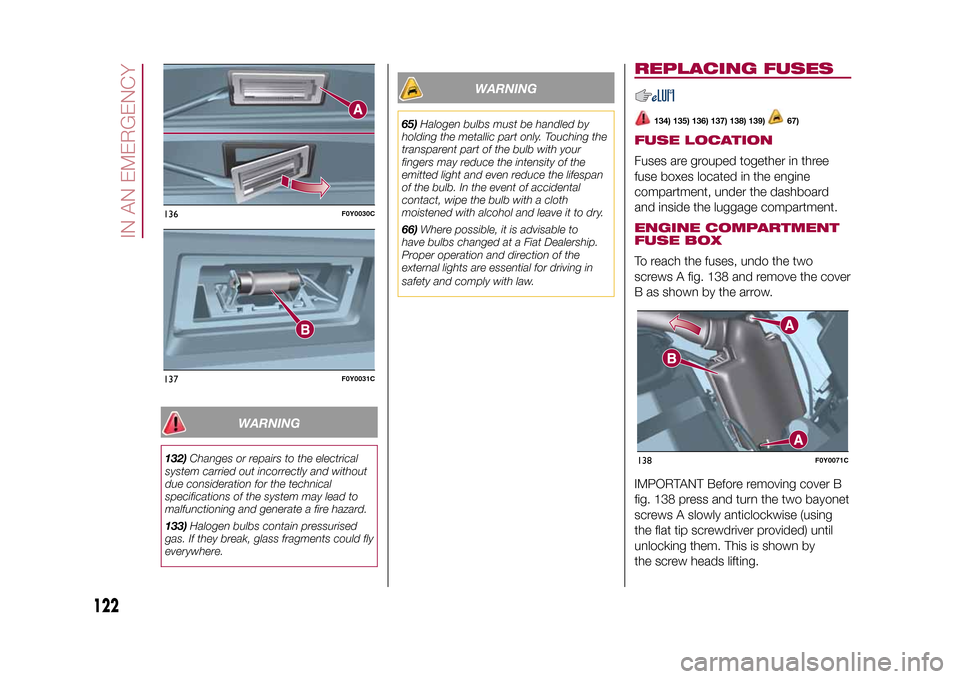
FUSE BOXTo reach the fuses, undo the two
screws A fig. 138 and remove the cover
B as shown by the arrow.
IMPORTANT Before removing cover B
fig. 138 press and turn the two bayonet
screws A slowly anticlockwise (using
the flat tip screwdriver provided) until
unlocking them. This is shown by
the screw heads lifting.
136
F0Y0030C
137
F0Y0031C
138
F0Y0071C
122
IN AN EMERGENCY
9-1-2015 12:9 Pagina 122
Page 131 of 224
If it is often necessary to perform a
jump starting, have the vehicle battery
and the recharging system checked
by a Fiat Dealership.
IMPORTANT Any accessories (e.g.
mobile phones, etc.) connected to the
vehicle power sockets draw current
even if they are not used. These
devices, if left connected too much time
with engine off, may cause the battery
to drain with following reduction of
its life and/or failure to start the engine.
WARNING
140)Do not get too close to the radiator
cooling fan: the electric fan may start;
danger of injury. Scarves, ties and other
loose clothing may be pulled by moving
parts.
141)Remove any metal objects (e.g. rings,
watches, bracelets), that might cause an
accidental electrical contact and cause
serious injury.
142)Batteries contain acid which may burn
skin and eyes. Batteries produce
hydrogen, which is easily flammable and
explosive. Thus keep away flames or
devices which may cause sparks.
WARNING
68)Do not connect the cable to the
negative terminal (–) of the flat battery. The
following spark could lead to battery
explosion and cause serious harm. Only
use the specific earth point; do not use any
other exposed metallic part.
FUEL CUT-OFF
SYSTEM
143)
This intervenes in the event of an
impact causing:
❒the interruption of the fuel supply with
the engine consequently cutting out
❒the automatic unlocking of the doors
❒the automatic switching on of the
interior lights
❒the switching on of the hazard
warning lights.
On some versions, the intervention of
the system is indicated by a message
shown on the display.
IMPORTANT Carefully check the car for
fuel leaks, for instance in the engine
compartment, under the car or near the
tank area. After a collision, turn the
ignition key to STOP to prevent the
battery from running down.
To restore the correct operation of the
car, proceed as follows:
❒turn the ignition key to the MAR
position;
❒activate the right direction indicator
and then stop it;
❒activate the left direction indicator
and then stop it;
❒activate the right direction indicator
and then stop it;
129
9-1-2015 12:9 Pagina 129