FIAT 500L LIVING 2017 2.G Owners Manual
Manufacturer: FIAT, Model Year: 2017, Model line: 500L LIVING, Model: FIAT 500L LIVING 2017 2.GPages: 240, PDF Size: 5.26 MB
Page 121 of 240
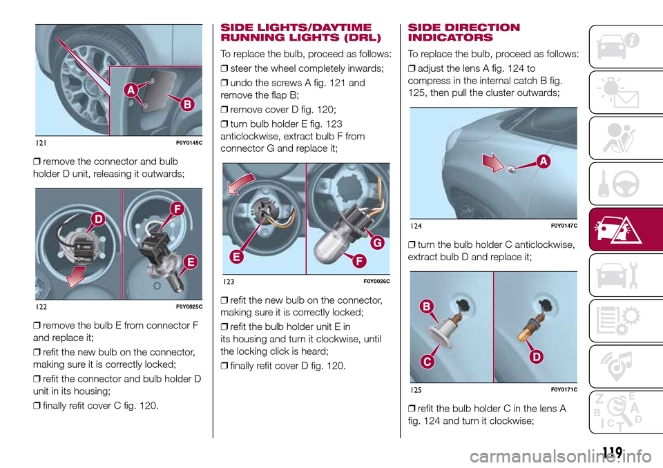
❒remove the connector and bulb
holder D unit, releasing it outwards;
❒remove the bulb E from connector F
and replace it;
❒refit the new bulb on the connector,
making sure it is correctly locked;
❒refit the connector and bulb holder D
unit in its housing;
❒finally refit cover C fig. 120.
SIDE LIGHTS/DAYTIME
RUNNING LIGHTS (DRL)
To replace the bulb, proceed as follows:
❒steer the wheel completely inwards;
❒undo the screws A fig. 121 and
remove the flap B;
❒remove cover D fig. 120;
❒turn bulb holder E fig. 123
anticlockwise, extract bulb F from
connector G and replace it;
❒refit the new bulb on the connector,
making sure it is correctly locked;
❒refit the bulb holder unit E in
its housing and turn it clockwise, until
the locking click is heard;
❒finally refit cover D fig. 120.
SIDE DIRECTION
INDICATORS
To replace the bulb, proceed as follows:
❒adjust the lens A fig. 124 to
compress in the internal catch B fig.
125, then pull the cluster outwards;
❒turn the bulb holder C anticlockwise,
extract bulb D and replace it;
❒refit the bulb holder C in the lens A
fig. 124 and turn it clockwise;
121F0Y0145C
122F0Y0025C
123F0Y0026C
124F0Y0147C
125F0Y0171C
119
Page 122 of 240
❒refit the cluster making sure that the
internal catch B fig. 125 clips into
position.
FOG LIGHTS(for versions/markets, where provided)
To replace the bulb, proceed as follows:
❒steer the wheel completely inwards;
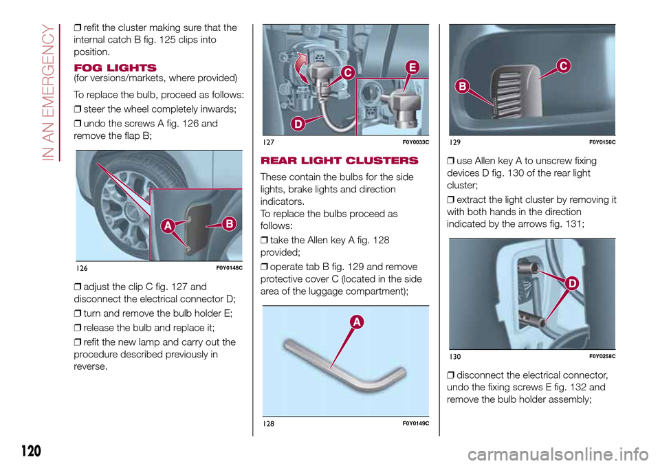
❒undo the screws A fig. 126 and
remove the flap B;
❒adjust the clip C fig. 127 and
disconnect the electrical connector D;
❒turn and remove the bulb holder E;
❒release the bulb and replace it;
❒refit the new lamp and carry out the
procedure described previously in
reverse.
REAR LIGHT CLUSTERS
These contain the bulbs for the side
lights, brake lights and direction
indicators.
To replace the bulbs proceed as
follows:
❒take the Allen key A fig. 128
provided;
❒operate tab B fig. 129 and remove
protective cover C (located in the side
area of the luggage compartment);❒use Allen key A to unscrew fixing
devices D fig. 130 of the rear light
cluster;
❒extract the light cluster by removing it
with both hands in the direction
indicated by the arrows fig. 131;
❒disconnect the electrical connector,
undo the fixing screws E fig. 132 and
remove the bulb holder assembly;
126F0Y0148C
127F0Y0033C
128F0Y0149C
129F0Y0150C
130F0Y0258C
120
IN AN EMERGENCY
Page 123 of 240
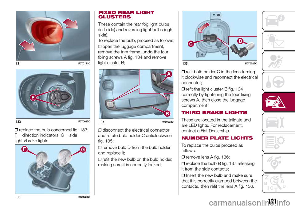
❒replace the bulb concerned fig. 133:
F = direction indicators, G = side
lights/brake lights.❒open the luggage compartment,
remove the trim frame, undo the four
fixing screws A fig. 134 and remove
light cluster B;
❒disconnect the electrical connector
and rotate bulb holder C anticlockwise
fig. 135;
❒remove bulb D from the bulb holder
and replace it;
❒refit the new bulb on the bulb holder,
making sure it is correctly locked;❒refit bulb holder C in the lens turning
it clockwise and reconnect the electrical
connector;
❒refit the light cluster B fig. 134
correctly by tightening the four fixing
screws A, then close the luggage
compartment.
THIRD BRAKE LIGHTS
These are located in the tailgate and
are LED lights. For replacement,
contact a Fiat Dealership.
NUMBER PLATE LIGHTS
To replace the bulbs proceed as
follows:
❒remove lens A fig. 136;
❒replace the bulb B fig. 137 releasing
it from the side contacts;
❒Insert the new bulb and make sure
that it is correctly clamped between the
contacts, then refit the lens A fig. 136.
131F0Y0151C
132F0Y0027C
133F0Y0028C
134F0Y0032C
135F0Y0029C
121
FIXED REAR LIGHT
CLUSTERS
These contain the rear fog light bulbs
(left side) and reversing light bulbs (right
side).
To replace the bulb, proceed as follows:
Page 124 of 240
WARNING
132)Changes or repairs to the electrical
system carried out incorrectly and without
due consideration for the technical
specifications of the system may lead to
malfunctioning and generate a fire hazard.
133)Halogen bulbs contain pressurised
gas. If they break, glass fragments could fly
everywhere.
WARNING
65)Halogen bulbs must be handled by
holding the metallic part only. Touching the
transparent part of the bulb with your
fingers may reduce the intensity of the
emitted light and even reduce the lifespan
of the bulb. In the event of accidental
contact, wipe the bulb with a cloth
moistened with alcohol and leave it to dry.
66)Where possible, it is advisable to
have bulbs changed at a Fiat Dealership.
Proper operation and direction of the
external lights are essential for driving in
safety and comply with law.
REPLACING FUSES
134) 135) 136) 137) 138) 139)67)
FUSE LOCATION
Fuses are grouped together in three
fuse boxes located in the engine
compartment, under the dashboard
and inside the luggage compartment.
ENGINE COMPARTMENT
FUSE BOX
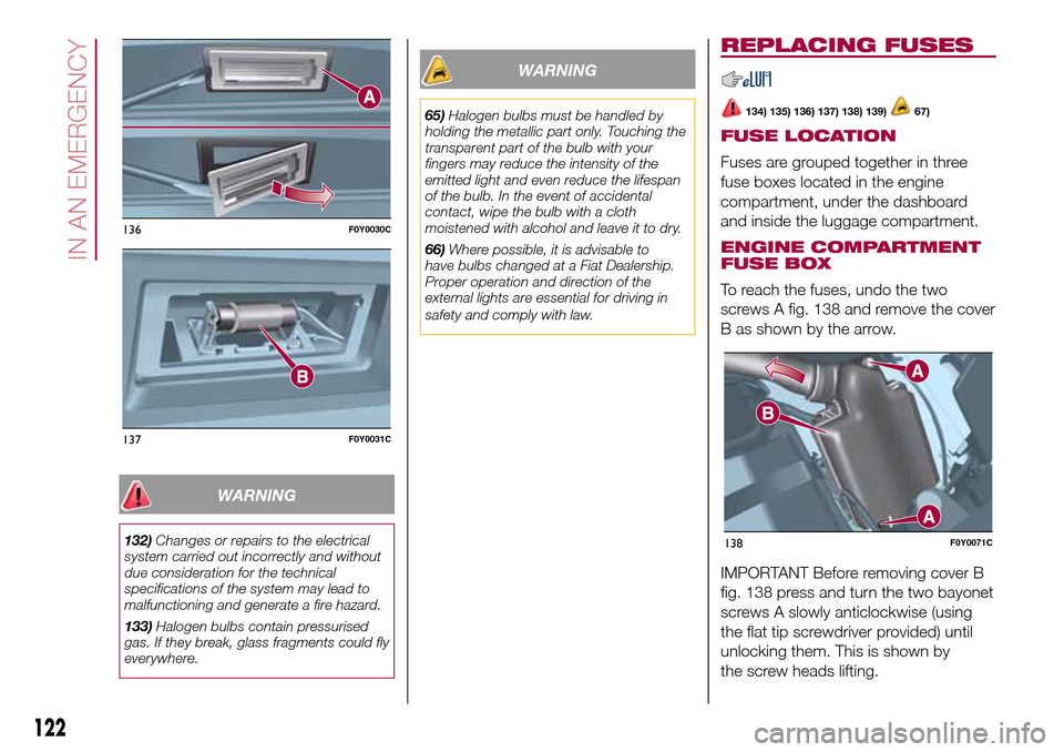
To reach the fuses, undo the two
screws A fig. 138 and remove the cover
B as shown by the arrow.
IMPORTANT Before removing cover B
fig. 138 press and turn the two bayonet
screws A slowly anticlockwise (using
the flat tip screwdriver provided) until
unlocking them. This is shown by
the screw heads lifting.
136F0Y0030C
137F0Y0031C
138F0Y0071C
122
IN AN EMERGENCY
Page 125 of 240

After replacing the fuse, make sure you
close cover B on the junction unit.
The fuse box is located by the side of
the battery fig. 139.
139F0Y0072C
123
Page 126 of 240

DASHBOARD FUSE BOX
The fuse box is located on the left side of the dashboard. To access the fuses, remove flap A fig. 140.
140F0Y0280C
124
IN AN EMERGENCY
Page 127 of 240

LUGGAGE COMPARTMENT FUSE BOX
The fuse box is located on the left side of the luggage compartment. To access the fuses operate in the point shown by the
arrow and remove flap A fig. 141.
141F0Y0177C
125
Page 128 of 240
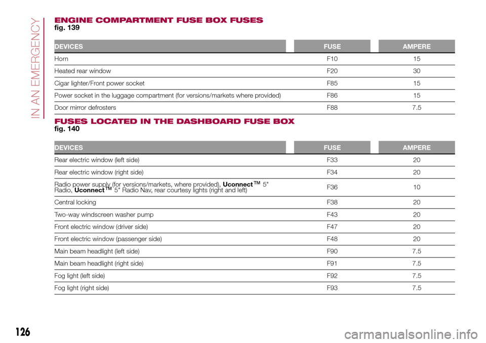
ENGINE COMPARTMENT FUSE BOX FUSESfig. 139
DEVICESFUSE AMPERE
HornF10 15
Heated rear windowF20 30
Cigar lighter/Front power socket F85 15
Power socket in the luggage compartment (for versions/markets where provided) F86 15
Door mirror defrostersF88 7.5
FUSES LOCATED IN THE DASHBOARD FUSE BOXfig. 140
DEVICESFUSE AMPERE
Rear electric window (left side) F33 20
Rear electric window (right side) F34 20
Radio power supply (for versions/markets, where provided),Uconnect
™5"
Radio,Uconnect™5" Radio Nav, rear courtesy lights (right and left)F36 10
Central lockingF38 20
Two-way windscreen washer pump F43 20
Front electric window (driver side) F47 20
Front electric window (passenger side) F48 20
Main beam headlight (left side) F90 7.5
Main beam headlight (right side) F91 7.5
Fog light (left side)F92 7.5
Fog light (right side)F93 7.5
126
IN AN EMERGENCY
Page 129 of 240

FUSES LOCATED IN THE LUGGAGE COMPARTMENT FUSE BOXfig. 141
DEVICESFUSE AMPERE
Front seat electric lumbar regulator F1 15
Front seat electrical heater F2 15
Hi-Fi systemF3 20
Electric sun roof blindF5 20
Electric sun roofF6 20
WARNING
134)If the replaced fuse blows again, contact a Fiat Dealership.
135)Never replace a fuse with metal wires or other material.
136)Never replace a fuse with another with a higher amp rating; DANGER OF FIRE.
137)If a general protection fuse (MEGA-FUSE, MIDI-FUSE, MAXI-FUSE) blows, contact a Fiat Dealership.
138)Before replacing a fuse, make sure that the ignition key has been removed and that all the other devices are switched off and/or
deactivated.
139)If a general protection fuse for the safety systems (airbag system, braking system), power unit systems (engine system, gearbox system)
or driving system blows, contact a Fiat Dealership.
WARNING
67)If it is necessary to wash the engine compartment, take care not to directly hit the fuse box and the window wiper motors with the water
jet.
127
Page 130 of 240
JUMP STARTING
If the battery is flat, a jump starting can
be performed using the battery and
the cables of another vehicle, or using a
booster battery.
IMPORTANT
When a booster battery is used, comply
with the utilisation and precaution
instructions specified by the producer.
Do not use the booster battery or
any other source of external supply with
a voltage above 12 V: the battery, the
starter, the alternator and the electrical
system of the vehicle could be
damaged.
Do not attempt jump starting if the
battery is frozen. The battery could
break and explode!
PREPARATION TO JUMP
STARTING
140) 141) 142)68)
IMPORTANT The positive terminal (+) of
the battery is shielded by a protective
cover. Lift the cover to access the
positive terminal.
Proceed as follows:
❒engage the handbrake, move the
Dualogic gear lever to P (Park) or,
for versions with manual gearbox, to
neutral and bring the ignition key to
STOP;❒switch off all the other electrical
devices in the vehicle;
❒if another vehicle is ready for jump
starting, park the vehicle within the
reach of the cables to be used for
starting, operate the handbrake and
make sure that the ignition is
deactivated.
IMPORTANT Avoid contact between
the two vehicles since this could cause
a connection to earth and may result
in serious injury to any people nearby.
PROCEDURE FOR JUMP
STARTING
IMPORTANT If the procedure below is
carried out incorrectly, it can cause
severe injury to people or damage the
recharging system of one or both
vehicles. Carefully follow the
instructions given below.
Cable connection
Proceed as follows to carry out a jump
starting:
❒connect one end of the cable used
for positive (+) to the positive terminal
(+) of the vehicle with flat battery;
❒connect the other end of the cable
used for positive (+) to the positive
terminal (+) of the auxiliary battery;❒connect one end of the cable used
for negative (–) to the negative terminal
(–) of the auxiliary battery;
❒connect the other end of the cable
used for negative (–) to an engine earth
(the visible metal part of the vehicle
engine with flat battery) away from the
battery and the fuel injection system;
❒start the vehicle engine with the
auxiliary battery, let it run for a
few minutes at idling. Start the engine
of the vehicle with flat battery.
Cable disconnection
Once the engine has been started,
remove the cables proceeding as
follows:
❒disconnect the end of the cable used
for negative (–) from the engine earth
of the vehicle with flat battery;
❒disconnect the other end of the cable
used for negative (–) from the negative
terminal (–) of the auxiliary battery;
❒disconnect the end of the cable used
for positive (+) from the positive terminal
(+) of the auxiliary battery;
❒disconnect one end of the cable
used for positive (+) from the positive
terminal (+) of the vehicle with flat
battery.
128
IN AN EMERGENCY