FIAT 500L LIVING 2017 2.G Owners Manual
Manufacturer: FIAT, Model Year: 2017, Model line: 500L LIVING, Model: FIAT 500L LIVING 2017 2.GPages: 240, PDF Size: 5.26 MB
Page 111 of 240
HAZARD WARNING
LIGHTS
CONTROL
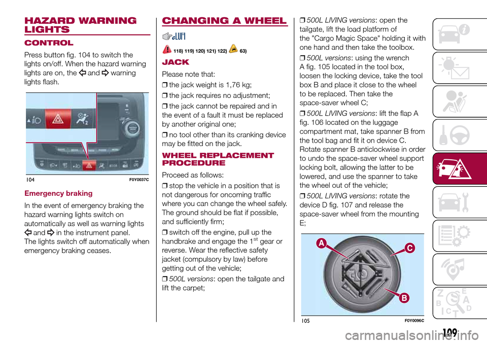
Press button fig. 104 to switch the
lights on/off. When the hazard warning
lights are on, the
andwarning
lights flash.
Emergency braking
In the event of emergency braking the
hazard warning lights switch on
automatically as well as warning lights
andin the instrument panel.
The lights switch off automatically when
emergency braking ceases.
CHANGING A WHEEL
118) 119) 120) 121) 122)63)
JACK
Please note that:
❒the jack weight is 1,76 kg;
❒the jack requires no adjustment;
❒the jack cannot be repaired and in
the event of a fault it must be replaced
by another original one;
❒no tool other than its cranking device
may be fitted on the jack.
WHEEL REPLACEMENT
PROCEDURE
Proceed as follows:
❒stop the vehicle in a position that is
not dangerous for oncoming traffic
where you can change the wheel safely.
The ground should be flat if possible,
and sufficiently firm;
❒switch off the engine, pull up the
handbrake and engage the 1
stgear or
reverse. Wear the reflective safety
jacket (compulsory by law) before
getting out of the vehicle;
❒500L versions: open the tailgate and
lift the carpet;❒500L LIVING versions: open the
tailgate, lift the load platform of
the "Cargo Magic Space" holding it with
one hand and then take the toolbox.
❒500L versions: using the wrench
A fig. 105 located in the tool box,
loosen the locking device, take the tool
box B and place it close to the wheel
to be replaced. Then take the
space-saver wheel C;
❒500L LIVING versions: lift the flap A
fig. 106 located on the luggage
compartment mat, take spanner B from
the tool bag and fit it on device C.
Rotate spanner B anticlockwise in order
to undo the space-saver wheel support
locking bolt, allowing the latter to be
lowered, and use the spanner to take
the wheel out of the vehicle;
❒500L LIVING versions: rotate the
device D fig. 107 and release the
space-saver wheel from the mounting
E;
104F0Y0037C
105F0Y0096C
109
Page 112 of 240
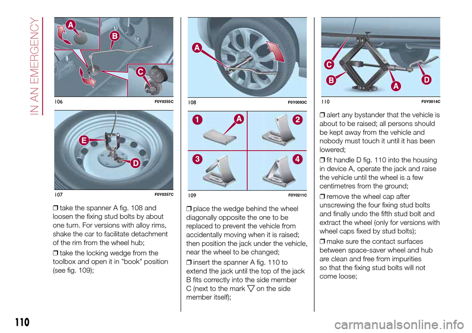
❒take the spanner A fig. 108 and
loosen the fixing stud bolts by about
one turn. For versions with alloy rims,
shake the car to facilitate detachment
of the rim from the wheel hub;
❒take the locking wedge from the
toolbox and open it in "book" position
(see fig. 109);❒place the wedge behind the wheel
diagonally opposite the one to be
replaced to prevent the vehicle from
accidentally moving when it is raised;
then position the jack under the vehicle,
near the wheel to be changed;
❒insert the spanner A fig. 110 to
extend the jack until the top of the jack
B fits correctly into the side member
C (next to the mark
on the side
member itself);❒alert any bystander that the vehicle is
about to be raised; all persons should
be kept away from the vehicle and
nobody must touch it until it has been
lowered;
❒fit handle D fig. 110 into the housing
in device A, operate the jack and raise
the vehicle until the wheel is a few
centimetres from the ground;
❒remove the wheel cap after
unscrewing the four fixing stud bolts
and finally undo the fifth stud bolt and
extract the wheel (only for versions with
wheel caps fixed by stud bolts);
❒make sure the contact surfaces
between space-saver wheel and hub
are clean and free from impurities
so that the fixing stud bolts will not
come loose;
106F0Y0355C
107F0Y0357C
108F0Y0093C
109F0Y0211C
110F0Y0014C
110
IN AN EMERGENCY
Page 113 of 240
❒fit the space-saver wheel by inserting
the first stud bolt for two threads into
the hole closest to the valve; then,
tighten the stud bolt by some threads
and proceed in the same way for the
others;
❒take the spanner A fig. 105 and fully
tighten the fixing stud bolts;
❒operate the jack handle D to lower
the car. Then extract the jack;
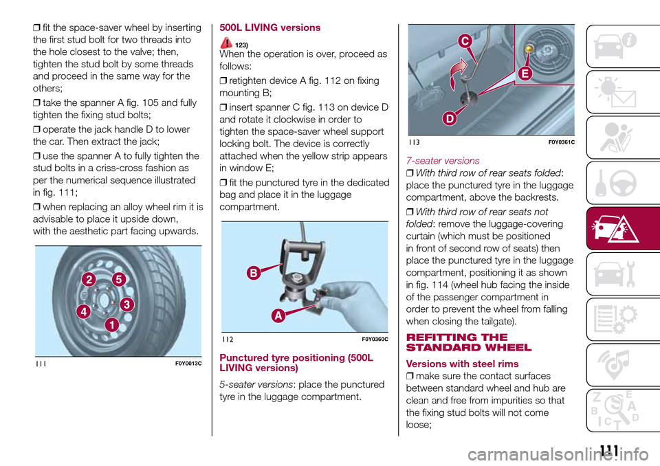
❒use the spanner A to fully tighten the
stud bolts in a criss-cross fashion as
per the numerical sequence illustrated
in fig. 111;
❒when replacing an alloy wheel rim it is
advisable to place it upside down,
with the aesthetic part facing upwards.500L LIVING versions
123)When the operation is over, proceed as
follows:
❒retighten device A fig. 112 on fixing
mounting B;
❒insert spanner C fig. 113 on device D
and rotate it clockwise in order to
tighten the space-saver wheel support
locking bolt. The device is correctly
attached when the yellow strip appears
in window E;
❒fit the punctured tyre in the dedicated
bag and place it in the luggage
compartment.
Punctured tyre positioning (500L
LIVING versions)
5-seater versions: place the punctured
tyre in the luggage compartment.
7-seater versions
❒With third row of rear seats folded:
place the punctured tyre in the luggage
compartment, above the backrests.
❒With third row of rear seats not
folded: remove the luggage-covering
curtain (which must be positioned
in front of second row of seats) then
place the punctured tyre in the luggage
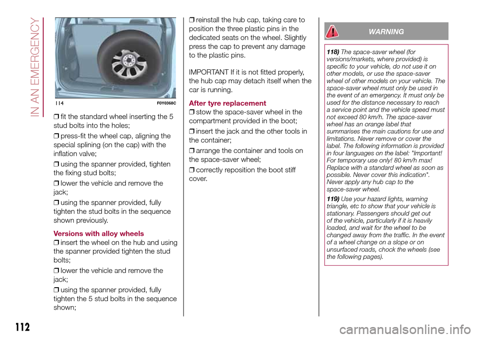
compartment, positioning it as shown
in fig. 114 (wheel hub facing the inside
of the passenger compartment in
order to prevent the wheel from falling
when closing the tailgate).
REFITTING THE
STANDARD WHEEL
Versions with steel rims
❒make sure the contact surfaces
between standard wheel and hub are
clean and free from impurities so that
the fixing stud bolts will not come
loose;
111F0Y0013C
112F0Y0360C
113F0Y0361C
111
Page 114 of 240
❒fit the standard wheel inserting the 5
stud bolts into the holes;
❒press-fit the wheel cap, aligning the
special splining (on the cap) with the
inflation valve;
❒using the spanner provided, tighten
the fixing stud bolts;
❒lower the vehicle and remove the
jack;
❒using the spanner provided, fully
tighten the stud bolts in the sequence
shown previously.
Versions with alloy wheels
❒insert the wheel on the hub and using
the spanner provided tighten the stud
bolts;
❒lower the vehicle and remove the
jack;
❒using the spanner provided, fully
tighten the 5 stud bolts in the sequence
shown;❒reinstall the hub cap, taking care to
position the three plastic pins in the
dedicated seats on the wheel. Slightly
press the cap to prevent any damage
to the plastic pins.
IMPORTANT If it is not fitted properly,
the hub cap may detach itself when the
car is running.
After tyre replacement
❒stow the space-saver wheel in the
compartment provided in the boot;
❒insert the jack and the other tools in
the container;
❒arrange the container and tools on
the space-saver wheel;
❒correctly reposition the boot stiff
cover.
WARNING
118)The space-saver wheel (for
versions/markets, where provided) is
specific to your vehicle, do not use it on
other models, or use the space-saver
wheel of other models on your vehicle. The
space-saver wheel must only be used in
the event of an emergency. It must only be
used for the distance necessary to reach
a service point and the vehicle speed must
not exceed 80 km/h. The space-saver
wheel has an orange label that
summarises the main cautions for use and
limitations. Never remove or cover the
label. The following information is provided
in four languages on the label: "Important!
For temporary use only! 80 km/h max!
Replace with a standard wheel as soon as
possible. Never cover this indication".
Never apply any hub cap to the
space-saver wheel.
119)Use your hazard lights, warning
triangle, etc to show that your vehicle is
stationary. Passengers should get out
of the vehicle, particularly if it is heavily
loaded, and wait for the wheel to be
changed away from the traffic. In the event
of a wheel change on a slope or on
unsurfaced roads, chock the wheels (see
the following pages).
114F0Y0368C
112
IN AN EMERGENCY
Page 115 of 240
120)Vehicle handling is modified with the
space-saver wheel fitted. Avoid violent
acceleration and braking, abrupt steering
and fast cornering. The overall duration
of the space-saver wheel is about 3000
km, after which the relevant tyre must be
replaced with another one of the same
type. Never install a standard tyre on a rim
that is designed for use with a space-saver
wheel. Have the wheel repaired and refitted
as soon as possible. Using two or more
space-saver wheels at the same time
is forbidden. Do not grease the threads of
the stud bolts before fitting them: they
might slip out when driving.
121)The jack shall only be used for raising
the car model it has been supplied with.
Never use the jack for other purposes,
such as raising other car models. Never
use the jack for repair operations under the
vehicle. Incorrect positioning of the jack
may cause the vehicle to fall. Do not use
the jack for loads higher than the one
shown on its label. The space-saver wheel
cannot be fitted with snow chains. If a
front (drive) tyre is punctured and chains
are needed, use a standard wheel from the
rear axle and install the space-saver wheel
on the rear axle. This way, with two
standard front driving wheels, you can
install the snow chains on them.
122)Incorrect hub cap assembly may
cause it to come off when the vehicle is
moving. Never tamper with the inflation
valve. Never introduce tools of any kind
between rim and tyre. Check tyre and
space-saver wheel pressures regularly,
complying with the values given in the
"Technical specifications" chapter.123)At the end of the operation of
raising/locking the spare wheel, the ignition
key must be extracted, taking care not to
turn it in the wrong direction to facilitate the
extraction of the key itself, to prevent the
attachment device from being released and
the wheel assembly not being securely
retained.
WARNING
63)Contact a Fiat Dealership as soon as
possible to have the correct tightening
of the wheel stud bolts checked.
"Fix&Go Automatic"
kit
124) 125) 126) 127) 128) 129) 130) 131)
64)3)
DESCRIPTION
The "Fix&Go Automatic" kit is located in
the luggage compartment, inside a
dedicated container. Inside the
container there are also a screwdriver,
the tow ring and the funnel for
refuelling, in the event of an emergency.
To access the kit, open the tailgate,
remove the load platform and lift the
carpet.
LPG versions: a tool box secured to
the luggage compartment carpet with
dedicated fastenings contains the kit.
The kit includes:
❒a bottle A fig. 115 containing sealing
fluid and fitted with: filling tube B and
adhesive label C with the wording
“max. 80 km/h” to be placed in a
clearly visible position (e.g. on
the dashboard) after repairing the tyre;
❒a compressor D including a pressure
gauge and connections, found in the
compartment;
113
Page 116 of 240
❒instruction booklet to be used for
prompt and correct use of the kit and
then to be handed to the personnel
charged with handling the treated tyre;
❒a pair of protective gloves located
in the side compartment of the
compressor;
❒adapters for inflating different
elements.
IMPORTANT The sealing fluid is
effective with external temperatures of
between –20°C and +50°C. The sealing
fluid has an expiry date.
INFLATION PROCEDURE
Proceed as follows:
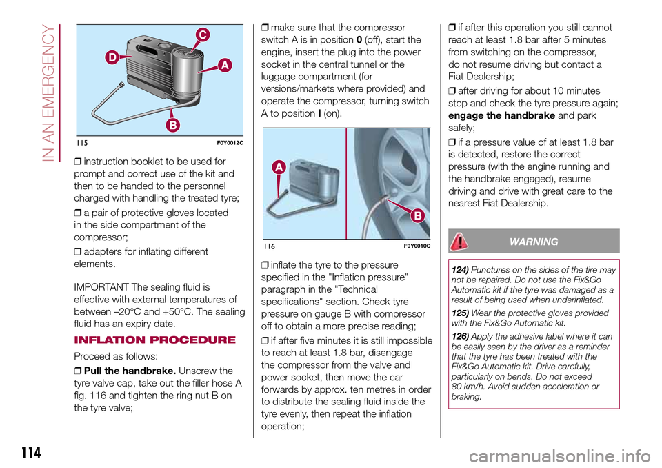
❒Pull the handbrake.Unscrew the
tyre valve cap, take out the filler hose A
fig. 116 and tighten the ring nut B on
the tyre valve;❒make sure that the compressor
switch A is in position0(off), start the
engine, insert the plug into the power
socket in the central tunnel or the
luggage compartment (for
versions/markets where provided) and
operate the compressor, turning switch
A to positionI(on).
❒inflate the tyre to the pressure
specified in the "Inflation pressure"
paragraph in the "Technical
specifications" section. Check tyre
pressure on gauge B with compressor
off to obtain a more precise reading;
❒if after five minutes it is still impossible
to reach at least 1.8 bar, disengage
the compressor from the valve and
power socket, then move the car
forwards by approx. ten metres in order
to distribute the sealing fluid inside the
tyre evenly, then repeat the inflation
operation;❒if after this operation you still cannot
reach at least 1.8 bar after 5 minutes
from switching on the compressor,
do not resume driving but contact a
Fiat Dealership;
❒after driving for about 10 minutes
stop and check the tyre pressure again;
engage the handbrakeand park
safely;
❒if a pressure value of at least 1.8 bar
is detected, restore the correct
pressure (with the engine running and
the handbrake engaged), resume
driving and drive with great care to the
nearest Fiat Dealership.
WARNING
124)Punctures on the sides of the tire may
not be repaired. Do not use the Fix&Go
Automatic kit if the tyre was damaged as a
result of being used when underinflated.
125)Wear the protective gloves provided
with the Fix&Go Automatic kit.
126)Apply the adhesive label where it can
be easily seen by the driver as a reminder
that the tyre has been treated with the
Fix&Go Automatic kit. Drive carefully,
particularly on bends. Do not exceed
80 km/h. Avoid sudden acceleration or
braking.
115F0Y0012C
116F0Y0010C
114
IN AN EMERGENCY
Page 117 of 240
127)If the pressure has fallen below 1.8
bar, do not drive any further: the Fix&Go
Automatic kit cannot guarantee proper
hold because the tyre is too damaged.
Contact a Fiat Dealership.
128)You must always indicate that the tyre
was repaired using the Fix&Go Automatic
kit. Give the booklet to the technicians who
will be handling the tyre that was treated
using the Fix&Go Automatic kit.
129)Repairs are not possible in the case of
damage to the wheel rim (bad groove
distortion causing air loss). Do not remove
foreign bodies (screws or nails) from the
tyre.
130)Never operate the compressor for
longer than 20 consecutive minutes. Risk
of overheating. The Fix&Go Automatic kit is
not suitable for definitive repairs, so the
repaired tyres may only be used
temporarily.
131)The information required by current
regulations, regarding the chemical
substances for the protection of human
health and the environment and on the safe
use of the sealing fluid, are on the
packaging label. Compliance with the
indications on the label is an essential
condition to ensure the safety and
the effectiveness of the product.
Remember to carefully read the label
before use; the user of the product
is responsible for any damages caused by
improper use. The sealing fluid has an
expiry date. Replace the bottle if the
sealant has expired.
WARNING
64)In the event of a puncture caused by
foreign bodies, the kit may be used to
repair tyres showing damage on the tread
or shoulder up to max. 4 mm diameter.
WARNING
3)Dispose of the bottle and the sealant
properly. Dispose of the components
in compliance with national and local
regulations.
REPLACING A BULB
132) 133)65) 66)
GENERAL
INSTRUCTIONS
❒Before changing a bulb check the
contacts for oxidation;
❒burnt bulbs must be replaced by
others of the same type and power;
❒after replacing a headlight bulb,
always check the correct alignment of
the light beam;
❒when a light is not working, check
that the corresponding fuse is intact
before changing a bulb. For the location
of fuses, refer to the paragraph “If a
fuse blows” in this section;
115
Page 118 of 240
IMPORTANT When the weather is cold
or damp or after heavy rain or washing,
the surface of headlights or rear lights,
may steam up and/or form drops of
condensation on the inside. This is
a natural phenomenon due to the
difference in temperature and humidity
between the inside and the outside
of the glass which does not indicate a
fault and does not compromise the
normal operation of lighting devices.
The mist disappears quickly when the
lights are turned on, starting from
the centre of the diffuser, extending
progressively towards the edges.
116
IN AN EMERGENCY
Page 119 of 240
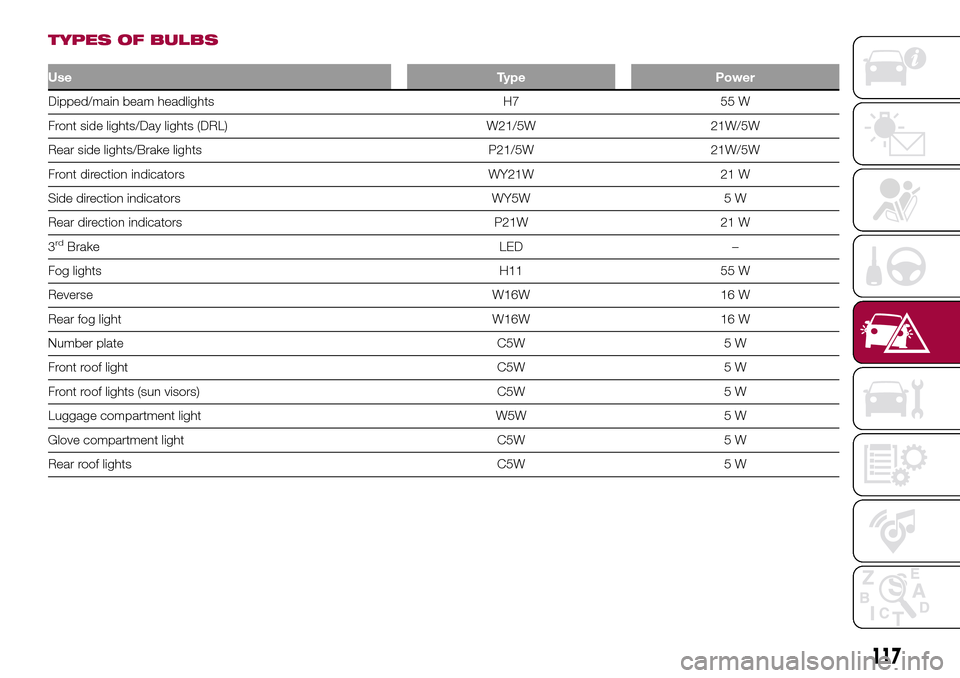
TYPES OF BULBS
UseType Power
Dipped/main beam headlights H7 55 W
Front side lights/Day lights (DRL) W21/5W 21W/5W
Rear side lights/Brake lights P21/5W 21W/5W
Front direction indicators WY21W 21 W
Side direction indicators WY5W 5 W
Rear direction indicators P21W 21 W
3
rdBrake LED –
Fog lights H11 55 W
Reverse W16W 16 W
Rear fog light W16W 16 W
Number plate C5W 5 W
Front roof light C5W 5 W
Front roof lights (sun visors) C5W 5 W
Luggage compartment light W5W 5 W
Glove compartment light C5W 5 W
Rear roof lights C5W 5 W
117
Page 120 of 240
FRONT UPPER LIGHT
CLUSTER
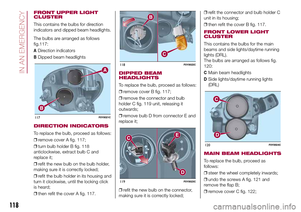
This contains the bulbs for direction
indicators and dipped beam headlights.
The bulbs are arranged as follows
117:
ADirection indicators
BDipped beam headlights
DIRECTION INDICATORS
To replace the bulb, proceed as follows:
❒remove cover A fig. 117;
❒turn bulb holder B fig. 118
anticlockwise, extract bulb C and
replace it;
❒refit the new bulb on the bulb holder,
making sure it is correctly locked;
❒refit the bulb holder in its housing and
turn it clockwise, until the locking click
is heard;
❒then refit the cover A fig. 117.
DIPPED BEAM
HEADLIGHTS
To replace the bulb, proceed as follows:
❒remove cover B fig. 117;
❒remove the connector and bulb
holder C fig. 119 unit, releasing it
outwards;
❒remove bulb D from connector E and
replace it;
❒refit the new bulb on the connector,
making sure it is correctly locked;❒refit the connector and bulb holder C
unit in its housing;
❒then refit the cover B fig. 117.
FRONT LOWER LIGHT
CLUSTER
This contains the bulbs for the main
beams and side lights/daytime running
lights (DRL).
The bulbs are arranged as follows fig.
120:
CMain beam headlights
DSide lights/daytime running lights
(DRL)
MAIN BEAM HEADLIGHTS
To replace the bulb, proceed as
follows:
❒steer the wheel completely inwards;
❒undo the screws A fig. 121 and
remove the flap B;
❒remove cover C fig. 122;
117F0Y0021C
118F0Y0022C
119F0Y0023C
120F0Y0024C
118
IN AN EMERGENCY
fig.