ignition FIAT 500X 2017 Owner handbook (in English)
[x] Cancel search | Manufacturer: FIAT, Model Year: 2017, Model line: 500X, Model: FIAT 500X 2017Pages: 284, PDF Size: 11.14 MB
Page 164 of 284
 EMERGENCY
STARTING
69)
If the battery is flat, a jump starting can
be performed using the battery and the
cables of another vehicle, or using an
auxiliary battery. In all cases, the battery
used must")
EMERGENCY
STARTING
69)
If the battery is flat, a jump starting can
be performed using the battery and the
cables of another vehicle, or using an
auxiliary battery. In all cases, the battery
used must have a capacity equal to or
a little higher than the flat one.
IMPORTANT
Do not use an auxiliary battery or any
other source of external supply with a
voltage above 12 V: the battery, the
starter, the alternator and the electrical
system of the vehicle could be
damaged.
Do not attempt jump starting if the
battery is frozen. The battery could
break and explode!
JUMP STARTING
The vehicle battery is located in the
engine compartment, behind the left
light cluster.
161) 162) 163) 164)
IMPORTANT The positive terminal (+) of
the battery is shielded by a protective
element. Raise it to access the terminal.
Proceed as follows:
operate the parking brake, move the
lever to P (Park), for versions equipped
with automatic transmission, or neutral,
for versions with manual gearbox, then
set the ignition device to STOP;
switch off all the other electrical
appliances in the vehicle;
should you be using the battery of
another vehicle, park the other vehicle
within the range of the cables used for
the connection, operate the parking
brake and ensure that its ignition is off.
IMPORTANT If the procedure below is
carried out incorrectly, it can cause
severe injury to people or damage the
recharging system of one or both
vehicles. Carefully follow the
instructions given below.
Cable connection
70)
Proceed as follows to carry out bump
starting fig. 140:
connect one end of the cable used
for positive (+) to the positive terminal
(+) of the vehicle with flat battery;
connect the other end of the cable
used for positive (+) to the positive
terminal (+) of the auxiliary battery;
connect one end of the cable used
for negative (–) to the negative terminal
(–) of the auxiliary battery;
Connect the other end of the cable
used for negative (–) to an engine earth
(a visible metal part of the engine or
gearbox/transmission of the vehicle
with flat battery) away from the battery
and the fuel injection system;
start the vehicle engine with the
auxiliary battery, let it run for a few
minutes at idling. Start the engine of the
vehicle with flat battery.
Cable disconnection.
Once the engine is started, remove the
leads, reversing the order above.
If after a few attempts the engine does
not start, do not persist but contact a
Fiat Dealership.
If it is often necessary to perform an
emergency starting, have the vehicle
battery and the recharging system
checked by a Fiat Dealership.
140F1B0217C
162
IN AN EMERGENCY
Page 165 of 284
 IMPORTANT Any accessories (e.g.
mobile phones, etc.) connected to the
vehicle power sockets, draw current
even if they are not used. These
devices, if left connected too much time
with engine off, may")
IMPORTANT Any accessories (e.g.
mobile phones, etc.) connected to the
vehicle power sockets, draw current
even if they are not used. These
devices, if left connected too much time
with engine off, may cause the battery
to drain with following reduction of its
life and/or failure to start the engine.
WARNING
161)Before opening the bonnet, make
sure that the engine is off and that the
ignition key is in the STOP position. Follow
the indications on the plate underneath the
bonnet. We recommend that you remove
the key from the ignition if other people
remain in the vehicle. The vehicle should
always be left after the key has been
removed or turned to the STOP position.
During refuelling, make sure that the engine
is off (and that the ignition key is in the
STOP position).
162)Do not get too close to the radiator
cooling fan: the electric fan may start;
danger of injury. Scarves, ties and other
loose clothing might be pulled by moving
parts.
163)Remove any metal objects (e.g. rings,
watches, bracelets), that might cause an
accidental electrical contact and cause
serious injury.
164)The batteries contain acid that can
burn skin or eyes. Batteries produce
hydrogen, which is easily flammable and
explosive. Therefore, keep away flames or
devices which may cause sparks.
IMPORTANT
69)Never use a fast battery-charger to
start the engine as this could damage the
electronic systems of your vehicle,
particularly the ignition and engine fuel
supply control units.
70)Do not connect the cable to the
negative terminal (–) of the flat battery. The
following spark could lead to battery
explosion and cause serious harm. Only
use the specific earth point; do not use any
other exposed metallic part.
FUEL CUT-OFF
SYSTEM
DESCRIPTION
This intervenes in the case of an impact
causing:
the interruption of the fuel supply
with the engine consequently switching
off;
the automatic unlocking of the
doors;
turning on of the lights inside the
vehicle;
deactivation of climate control
system ventilation;
switching on of the hazard warning
lights (to deactivate the lights press the
button on the dashboard).
On some versions, the intervention of
the system is indicated by a message
shown on the display. In the same way,
a dedicated message on the display
warns the driver if system operation is
compromised.
IMPORTANT Carefully check the vehicle
for fuel leaks, for instance in the engine
compartment, under the vehicle or near
the tank area. After a collision, bring the
ignition device to STOP to prevent the
battery from running down.
163
Page 166 of 284
 FUEL CUT-OFF SYSTEM
RESET
165)
To restore correct operation of the car,
carry out the following procedure (this
procedure must be started and
completed within less than 1 minute):
with direction indic")
FUEL CUT-OFF SYSTEM
RESET
165)
To restore correct operation of the car,
carry out the following procedure (this
procedure must be started and
completed within less than 1 minute):
with direction indicator lever in
neutral position, turn the ignition device
to STOP;
turn the ignition device to MAR;
activate the right direction indicator
and then the left one;
activate the right direction indicator
and then the left one again;
deactivate the left direction indicator;
turn the ignition device to STOP and
then to MAR.
WARNING
165)If, after an impact, you smell fuel or
notice leaks from the fuel system, do not
reactivate the system to avoid the risk of
fire.
AUTOMATIC
TRANSMISSION -
LEVER UNLOCK
In the event of a fault, to move the gear
lever from P (Park), proceed as follows:
stop the engine;
engage the electric parking brake;
working carefully in the point
indicated by the arrow, remove the trim
A fig. 141 (complete with gaiter) lifting it
upwards (see also fig. 142 );
fully depress the brake pedal and
hold it down;
insert the screwdriver supplied
perpendicularly in hole B fig. 143 and
adjust the release lever;
place the gear lever in N (Neutral)
position;
refit the gear lever gaiter and trim
correctly;
start the engine.
141F1B0028C
142F1B0055C
143F1B0056C
164
IN AN EMERGENCY
Page 167 of 284
 AUTOMATIC
TRANSMISSION -
KEY REMOVAL
71)
The ignition key (for versions with key
without remote control) can be removed
only if the gear lever is in position P
(Park).
If the vehicle battery is flat a")
AUTOMATIC
TRANSMISSION -
KEY REMOVAL
71)
The ignition key (for versions with key
without remote control) can be removed
only if the gear lever is in position P
(Park).
If the vehicle battery is flat and the
ignition key is engaged, the latter is
locked in position.
To remove the key manually, proceed
as follows:
stop the vehicle in safety conditions,
engage a gear and the electric parking
brake;
using the provided key A
fig. 144 (located in the casing
containing the on-board documents),
undo the fixing screws B fig. 145 for the
lower cover C;
remove the lower steering wheel
cover C fig. 145 by releasing it from its
housing;
pull tab D fig. 146 downwards using
one hand and with the other one
remove the key, sliding it outwards;
once the key has been removed,
refit lower cover C fig. 145, make sure it
locks correctly and tighten the fixing
screws B firmly.
144F1B0022C
145F1B0143C
146F1B0222C
165
Page 169 of 284
 DUAL CLUTCH
AUTOMATIC
TRANSMISSION KEY
REMOVAL -
71)
The ignition key (for versions with key
without remote control) can be removed
only if the gear lever is in position P
(Park).
If the vehicle batte")
DUAL CLUTCH
AUTOMATIC
TRANSMISSION KEY
REMOVAL -
71)
The ignition key (for versions with key
without remote control) can be removed
only if the gear lever is in position P
(Park).
If the vehicle battery is flat and the
ignition key is engaged, the latter is
locked in position.
To remove the key manually, proceed
as follows:
stop the vehicle in safety conditions,
engage a gear and the electric parking
brake;
using the provided key A
fig. 150 (located in the casing
containing the on-board documents),
undo the fixing screws B fig. 151 for the
lower cover C;
remove the lower steering wheel
cover C fig. 151 by releasing it from its
housing;
pull tab D fig. 152 downwards using
one hand and with the other one
remove the key, sliding it outwards;
once the key has been removed,
refit lower cover C fig. 151, make sure it
locks correctly and tighten the fixing
screws B firmly.
150F1B0022C
151F1B0143C152F1B0222C
167
Page 170 of 284
 IMPORTANT
72)It is advisable to contact a Fiat
Dealership to have the refitting procedure
carried out. If you would like to proceed
autonomously, special attention must be
paid to the correct coupling")
IMPORTANT
72)It is advisable to contact a Fiat
Dealership to have the refitting procedure
carried out. If you would like to proceed
autonomously, special attention must be
paid to the correct coupling of the retaining
clips. Otherwise, noise might be heard due
to an incorrect fastening of the lower cover
with the upper cover.
TOWING THE
VEHICLE
ATTACHING THE TOW
HOOK
166) 167) 168)
The tow hook provided is located in the
tool box inside the boot.
Front
Proceed as follows:
release cap A fig. 153, operating in
the point shown by the arrow;
take tow hook B and screw it fully
onto the front threaded pin.
Rear
Proceed as follows:
release cap A fig. 154, operating in
the point shown by the arrow;
take tow hook B and screw it fully
onto the rear threaded pin
WARNING
166)For versions with key without remote
control, before towing, turn the ignition key
to MAR and then to STOP without
removing it. The steering column will
automatically lock when the key is removed
and the wheels cannot be steered. Also
check that the gearbox is in neutral (on
versions equipped with automatic
transmission, check that the gear lever is in
N position). For versions with electronic
key, move the ignition device to MAR and
then to STOP, without opening the door.
153F1B0196C
154F1B0197C
168
IN AN EMERGENCY
Page 192 of 284
 BATTERY
RECHARGING
IMPORTANT
IMPORTANT The battery recharging
procedure is given as information only.
To carry out this operation contact a
Fiat Dealership.
IMPORTANT After setting the ignition
device")
BATTERY
RECHARGING
IMPORTANT
IMPORTANT The battery recharging
procedure is given as information only.
To carry out this operation contact a
Fiat Dealership.
IMPORTANT After setting the ignition
device to STOP and having closed the
driver side door, wait at least one
minute before disconnecting the
electrical supply from the battery. When
reconnecting the electrical supply to the
battery, make sure that the ignition
device is in the STOP position and the
driver side door is closed.
IMPORTANT Charging should be slow
at a low ampere rating for
approximately 24 hours. Charging for a
longer time may damage the battery.IMPORTANT The cables of the
electrical system must be correctly
reconnected to the battery, i.e. the
positive cable (+) to the positive
terminal and the negative cable (–) to
the negative terminal. The battery
terminals are marked with the positive
(+) and negative (–) symbols, and are
shown on the battery cover. The battery
terminals must also be corrosion-free
and firmly secured to the terminals. If a
"quick-type" battery charger is used
with the battery fitted on the vehicle,
before connecting it disconnect both
cables of the battery itself. Do not use a
"quick-type" battery charger to provide
the starting voltage.
VERSIONS WITHOUT
START&STOP SYSTEM
To recharge, proceed as follows:
disconnect the terminal from the
negative battery pole;
connect the charger cables to the
battery terminals, observing the polarity;
turn on the charger;
when it is recharged, turn the
charger off before disconnecting it from
the battery;
reconnect the negative battery
terminal.
VERSIONS WITH
START&STOP SYSTEM
To recharge, proceed as follows:
disconnect the connector A
fig. 161 (pressing the button B) from the
sensor C monitoring the battery
conditions, on the negative pole (–) D of
the battery;
161F1B0300C
190
SERVICING AND MAINTENANCE
Page 194 of 284
 used for cleaning the rear view mirror.
Do not spray the detergent directly on
the glass.
Cleaning the window with hot water
could cause the removal of any labels.
WINDSCREEN / REAR
WINDOW WIPERS
Rais")
used for cleaning the rear view mirror.
Do not spray the detergent directly on
the glass.
Cleaning the window with hot water
could cause the removal of any labels.
WINDSCREEN / REAR
WINDOW WIPERS
Raising the windscreen wipers
If you need to lift the windscreen wiper
blades (e.g. in case of snow or when
they need to be replaced), you need to
activate the "Service Position" function
(see paragraph "Windscreen/Rear
window wiper" in the "Knowing your
vehicle" chapter).
To lower the blades, set the ignition
device to MAR-ON.
IMPORTANT Place the blades back in
contact with the windscreen before
activating the windscreen wiper again
and/or setting the ignition device to
MAR-ON.
Replacing the windscreen wiper
blades
Proceed as follows:
raise the wiper arm, press button A
fig. 162 of the attachment spring and
remove the blade from the arm;
fit the new blade, inserting the tab in
the dedicated housing in the arm and
checking that it is locked;
lower the wiper arm on the
windscreen.
IMPORTANT Do not operate the
windscreen wiper with the blades lifted
from the windscreen.
Replacing the rear window wiper
blade
Proceed as follows:
widen the two tabs as shown by the
arrows and rotate cover A
fig. 163 outwards;
undo nut B and remove arm C from
the central pin;
correctly align the new arm;
fully tighten nut B and then refit
cover A.
IMPORTANT Do not operate the rear
window wiper with the blade lifted from
the rear window.
NOZZLES
Windscreen washer
The window washer nozzles are fixed. If
there is no jet of fluid, firstly check that
there is fluid in the reservoir (see
paragraph “Engine compartment” in
this chapter). Then check that the
nozzle holes are not clogged; use a
needle to unblock them if necessary.
IMPORTANT In versions with sun roof,
make sure that the roof is closed before
operating the windscreen washer
nozzles.
Rear window washer
The rear window washer nozzle is fixed.
The jet nozzle is located at the side of
the third brake light.
162F1B0302C163F1B0303C
192
SERVICING AND MAINTENANCE
Page 198 of 284
 BODYWORK
PRESERVING THE
BODYWORK
Paintwork
89)
7)
Touch up abrasions and scratches
immediately to prevent the formation of
rust.
Maintenance of paintwork consists of
washing the vehicle: the frequency")
BODYWORK
PRESERVING THE
BODYWORK
Paintwork
89)
7)
Touch up abrasions and scratches
immediately to prevent the formation of
rust.
Maintenance of paintwork consists of
washing the vehicle: the frequency
depends on the conditions and
environment in which the vehicle is
used. For example, it is advisable to
wash the vehicle more often in areas
with high levels of atmospheric pollution
or salted roads.
Some parts of the vehicle may be
covered with a matt paint which, in
order to be maintained intact, requires
special care: see the instructions in the
warning at the end of this paragraph
90).
To correctly wash the vehicle, follow
these instructions:
if the vehicle is washed remove the
aerial from the roof;
if high pressure jets or cleaners are
used to wash the vehicle, keep a
distance of at least 40 cm from thebodywork to avoid damage or
alteration. Build up of water could
cause damage to the vehicle in the long
term;
wash the bodywork using a low
pressure jet of water if possible;
wipe a sponge with a slightly soapy
solution over the bodywork, frequently
rinsing the sponge;
rinse well with water and dry with a
jet of air or a chamois leather.
Dry the less visible parts (e.g. door
frames, bonnet, headlight frames, etc.)
with special care, as water may
stagnate more easily in these areas. Do
not wash the vehicle after it has been
left in the sun or with the bonnet hot:
this may alter the shine of the
paintwork.
Exterior plastic parts must be cleaned
in the same way as the rest of the
vehicle.
IMPORTANT
Avoid parking under trees; the resin
dropped by trees makes the paintwork
go opaque and increases the possibility
of corrosion.
Bird droppings must be washed off
immediately and thoroughly as the acid
they contain is particularly aggressive.Windows
Use specific detergents and clean
cloths to prevent scratching or altering
the transparency.
IMPORTANT Wipe the rear window
inside gently with a cloth following the
direction of the filaments to avoid
damaging the heating device.
Headlights
Use a soft cloth soaked in water and
detergent for washing cars.
IMPORTANT Never use aromatic
substances (e.g. petrol) or ketones (e.g.
acetone) for cleaning the plastic lenses
of the headlights.
IMPORTANT When cleaning with a
pressure washer, keep the water jet at
least 20 cm away from the headlights.
Engine compartment
At the end of every winter, wash the
engine compartment thoroughly, taking
care not to aim the jet of water directly
at the electronic control units or at the
windscreen/rear window wiper motors.
Have this operation performed at a
specialised workshop.
IMPORTANT The washing should take
place with the engine cold and the
ignition device in the STOP position.
After the washing operation, make sure
196
SERVICING AND MAINTENANCE
Page 239 of 284
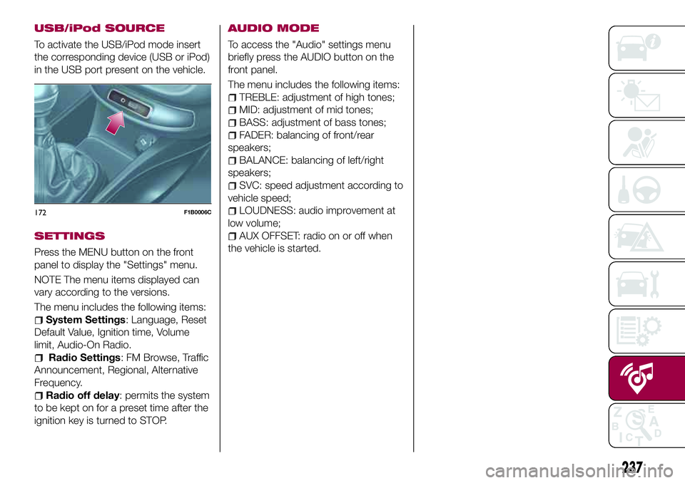
USB/iPod SOURCE
To activate the USB/iPod mode insert
the corresponding device (USB or iPod)
in the USB port present on the vehicle.
SETTINGS
Press the MENU button on the front
panel to display the "Settings" menu.
NOTE The menu items displayed can
vary according to the versions.
The menu includes the following items:
System Settings: Language, Reset
Default Value, Ignition time, Volume
limit, Audio-On Radio.
Radio Settings: FM Browse, Traffic
Announcement, Regional, Alternative
Frequency.
Radio off delay: permits the system
to be kept on for a preset time after the
ignition key is turned to STOP.
AUDIO MODE
To access the "Audio" settings menu
briefly press the AUDIO button on the
front panel.
The menu includes the following items:
TREBLE: adjustment of high tones;
MID: adjustment of mid tones;
BASS: adjustment of bass tones;
FADER: balancing of front/rear
speakers;
BALANCE: balancing of left/right
speakers;
SVC: speed adjustment according to
vehicle speed;
LOUDNESS: audio improvement at
low volume;
AUX OFFSET: radio on or off when
the vehicle is started.
172F1B0006C
237