FIAT 500X 2018 Owner handbook (in English)
Manufacturer: FIAT, Model Year: 2018, Model line: 500X, Model: FIAT 500X 2018Pages: 276, PDF Size: 7.08 MB
Page 21 of 276
SEATS
FRONT SEATS WITH
MANUAL ADJUSTMENT
11)
4)
Longitudinal adjustment
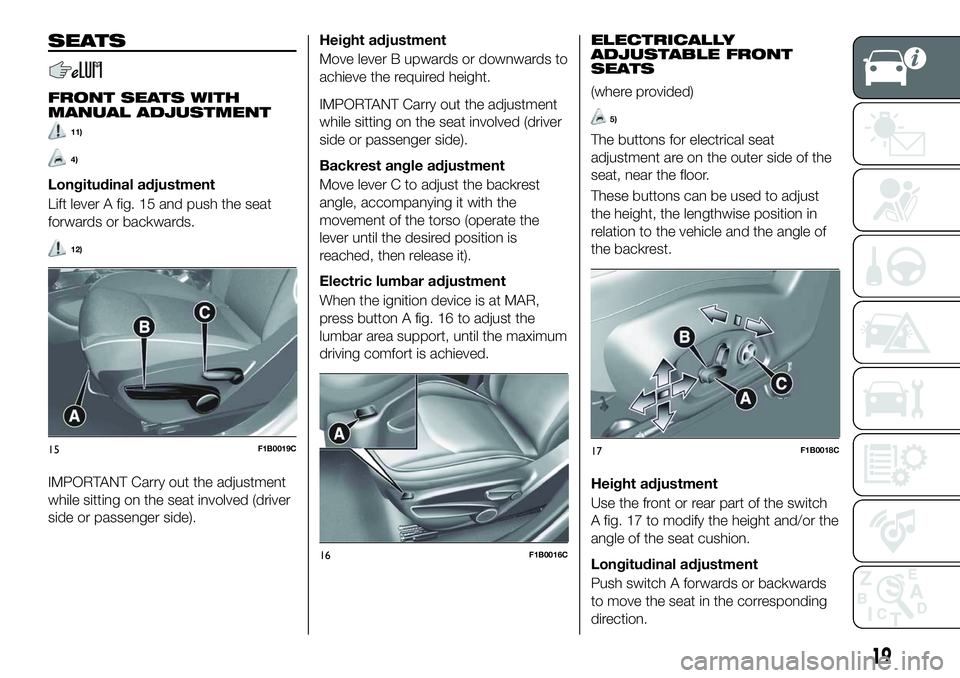
Lift lever A fig. 15 and push the seat
forwards or backwards.
12)
IMPORTANT Carry out the adjustment
while sitting on the seat involved (driver
side or passenger side).
Height adjustment
Move lever B upwards or downwards to
achieve the required height.
IMPORTANT Carry out the adjustment
while sitting on the seat involved (driver
side or passenger side).
Backrest angle adjustment
Move lever C to adjust the backrest
angle, accompanying it with the
movement of the torso (operate the
lever until the desired position is
reached, then release it).
Electric lumbar adjustment
When the ignition device is at MAR,
press button A fig. 16 to adjust the
lumbar area support, until the maximum
driving comfort is achieved.
ELECTRICALLY
ADJUSTABLE FRONT
SEATS
(where provided)
5)
The buttons for electrical seat
adjustment are on the outer side of the
seat, near the floor.
These buttons can be used to adjust
the height, the lengthwise position in
relation to the vehicle and the angle of
the backrest.
Height adjustment
Use the front or rear part of the switch
A fig. 17 to modify the height and/or the
angle of the seat cushion.
Longitudinal adjustment
Push switch A forwards or backwards
to move the seat in the corresponding
direction.
15F1B0019C
16F1B0016C
17F1B0018C
19
Page 22 of 276
Backrest angle adjustment
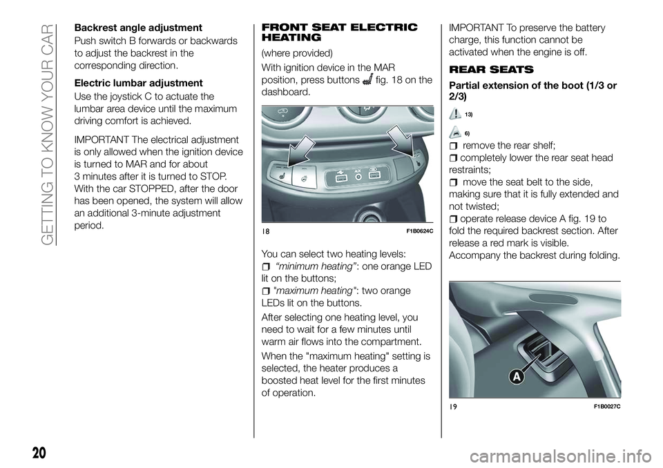
Push switch B forwards or backwards
to adjust the backrest in the
corresponding direction.
Electric lumbar adjustment
Use the joystick C to actuate the
lumbar area device until the maximum
driving comfort is achieved.
IMPORTANT The electrical adjustment
is only allowed when the ignition device
is turned to MAR and for about
3 minutes after it is turned to STOP.
With the car STOPPED, after the door
has been opened, the system will allow
an additional 3-minute adjustment
period.FRONT SEAT ELECTRIC
HEATING
(where provided)
With ignition device in the MAR
position, press buttons
fig. 18 on the
dashboard.
You can select two heating levels:
“minimum heating”: one orange LED
lit on the buttons;
"maximum heating": two orange
LEDs lit on the buttons.
After selecting one heating level, you
need to wait for a few minutes until
warm air flows into the compartment.
When the "maximum heating" setting is
selected, the heater produces a
boosted heat level for the first minutes
of operation.
IMPORTANT To preserve the battery
charge, this function cannot be
activated when the engine is off.
REAR SEATS
Partial extension of the boot (1/3 or
2/3)
13)
6)
remove the rear shelf;
completely lower the rear seat head
restraints;
move the seat belt to the side,
making sure that it is fully extended and
not twisted;
operate release device A fig. 19 to
fold the required backrest section. After
release a red mark is visible.
Accompany the backrest during folding.
18F1B0624C
19F1B0027C
20
GETTING TO KNOW YOUR CAR
Page 23 of 276
Repositioning the backrests
Move the seat belts to the side, making
sure that they are correctly extended
and not twisted.
Raise the backrests and push them
back until the locking click of both
retainers is heard. Visually check that
the red marks have disappeared from
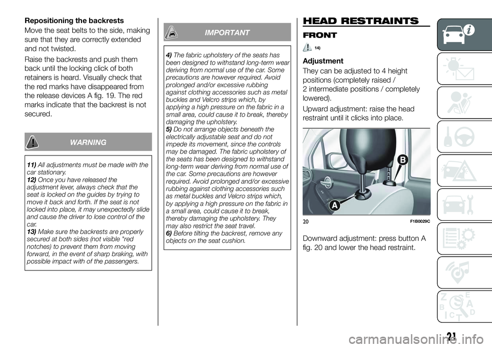
the release devices A fig. 19. The red
marks indicate that the backrest is not
secured.
WARNING
11)All adjustments must be made with the
car stationary.
12) Once you have released the
adjustment lever, always check that the
seat is locked on the guides by trying to
move it back and forth. If the seat is not
locked into place, it may unexpectedly slide
and cause the driver to lose control of the
car.
13) Make sure the backrests are properly
secured at both sides (not visible "red
notches) to prevent them from moving
forward, in the event of sharp braking, with
possible impact with of the passengers.
IMPORTANT
4) The fabric upholstery of the seats has
been designed to withstand long-term wear
deriving from normal use of the car. Some
precautions are however required. Avoid
prolonged and/or excessive rubbing
against clothing accessories such as metal
buckles and Velcro strips which, by
applying a high pressure on the fabric in a
small area, could cause it to break, thereby
damaging the upholstery.
5) Do not arrange objects beneath the
electrically adjustable seat and do not
impede its movement, since the controls
may be damaged. The fabric upholstery of
the seats has been designed to withstand
long-term wear deriving from normal use of
the car. Some precautions are however
required. Avoid prolonged and/or excessive
rubbing against clothing accessories such
as metal buckles and Velcro strips which,
by applying a high pressure on the fabric in
a small area, could cause it to break,
thereby damaging the upholstery. They
may also restrict the seat travel.
6) Before tilting the backrest, remove any
objects on the seat cushion.
HEAD RESTRAINTS
FRONT
14)
Adjustment
They can be adjusted to 4 height
positions (completely raised /
2 intermediate positions / completely
lowered).
Upward adjustment: raise the head
restraint until it clicks into place.
Downward adjustment: press button A
fig. 20 and lower the head restraint.
20F1B0029C
21
Page 24 of 276
Removal
Proceed as follows to remove the head
restraint:
tilt the backrest (to prevent it from
coming into contact with the roof);
press both buttons A and B fig. 20 at
the side of the two supports, then
remove the head restraint.
IMPORTANT Always reposition the
head restraints if they have been
removed before starting to drive
normally.
REAR
14)
Adjustment
Three head restraints that can be
height-adjusted to 3 positions
(completely raised / intermediate /
completely lowered) are provided for
the rear seats
Upward adjustment: raise the head
restraint until it clicks into place. On some versions, the label
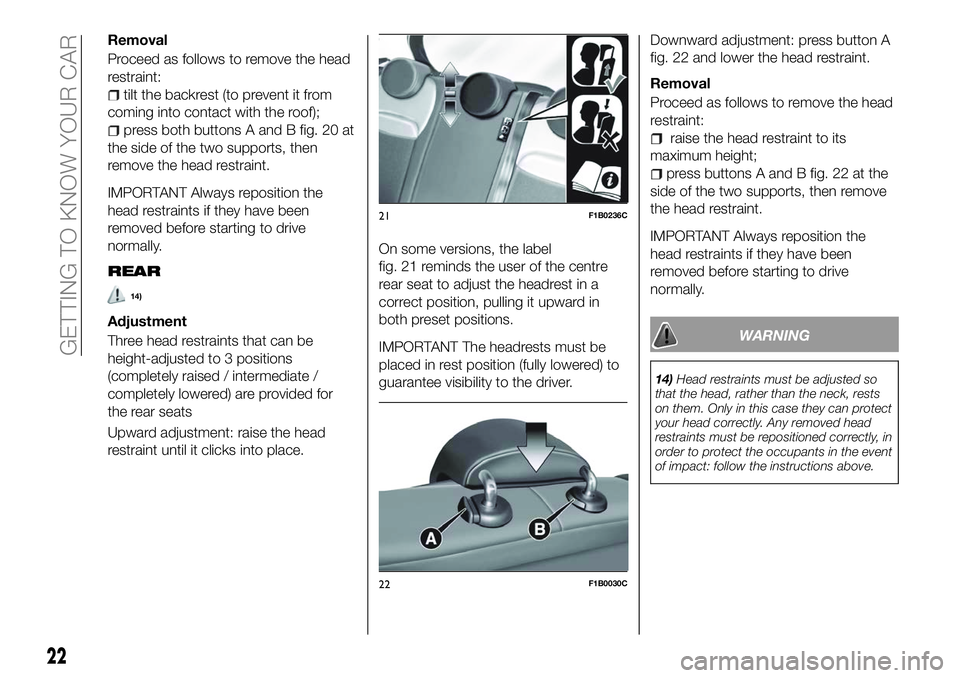
fig. 21 reminds the user of the centre
rear seat to adjust the headrest in a
correct position, pulling it upward in
both preset positions.
IMPORTANT The headrests must be
placed in rest position (fully lowered) to
guarantee visibility to the driver.
Downward adjustment: press button A
fig. 22 and lower the head restraint.
Removal
Proceed as follows to remove the head
restraint:
raise the head restraint to its
maximum height;
press buttons A and B fig. 22 at the
side of the two supports, then remove
the head restraint.
IMPORTANT Always reposition the
head restraints if they have been
removed before starting to drive
normally.
WARNING
14) Head restraints must be adjusted so
that the head, rather than the neck, rests
on them. Only in this case they can protect
your head correctly. Any removed head
restraints must be repositioned correctly, in
order to protect the occupants in the event
of impact: follow the instructions above.
21F1B0236C
22F1B0030C
22
GETTING TO KNOW YOUR CAR
Page 25 of 276
STEERING WHEEL
15) 16)
ADJUSTMENTS
The steering wheel can be adjusted
both in height and axially.
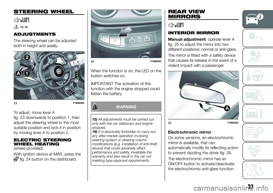
To adjust, move lever A
fig. 23 downwards to position 1, then
adjust the steering wheel to the most
suitable position and lock it in position
by moving lever A to position 2.
ELECTRIC STEERING
WHEEL HEATING
(where provided)
With ignition device at MAR, press the
fig. 24 button on the dashboard.When the function is on, the LED on the
button switches on.
IMPORTANT The activation of this
function with the engine stopped could
flatten the battery.
WARNING
15)
All adjustments must be carried out
only with the car stationary and engine
stopped.
16) It is absolutely forbidden to carry out
any after-market operation involving
steering system or steering column
modifications (e.g. installation of anti-theft
device) that could adversely affect
performance and safety, invalidate the
warranty and also result in the car not
meeting type-approval requirements.
REAR VIEW
MIRRORS
INTERIOR MIRROR
Manual adjustment: operate lever A
fig. 25 to adjust the mirror into two
different positions: normal or anti-glare.
The mirror is fitted with a safety device
that causes its release in the event of a
violent impact with a passenger.
Electrochromic mirror
On some versions, an electrochromic
mirror is available, that can
automatically modify its reflecting action
to prevent dazzling the driver fig. 26.
The electrochromic mirror has an
ON/OFF button to activate/deactivate
the electrochromic anti-glare function.
23F1B0628C
24F1B0625C
25F1B0033C
23
Page 26 of 276
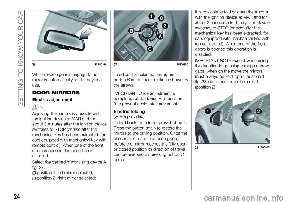
When reverse gear is engaged, the
mirror is automatically set for daytime
use.
DOOR MIRRORS
Electric adjustment
17)
Adjusting the mirrors is possible with
the ignition device at MAR and for
about 3 minutes after the ignition device
switches to STOP (or also after the
mechanical key has been extracted, for
cars equipped with mechanical key with
remote control). When one of the front
doors is opened this operation is
disabled.
Select the desired mirror using device A
fig. 27:
position 1: left mirror selected;
position 2: right mirror selected;To adjust the selected mirror, press
button B in the four directions shown by
the arrows.
IMPORTANT Once adjustment is
complete, rotate device A to position
0 to prevent accidental movements.
Electric folding
(where provided)
To fold back the mirrors press button C.
Press the button again to restore the
mirrors to the driving position. Once the
chosen command has been given,
before the mirror reaches the fully open
or closed position its direction of travel
can be reversed by pressing button C
again. It is possible to fold or open the mirrors
with the ignition device at MAR and for
about 3 minutes after the ignition device
switches to STOP (or also after the
mechanical key has been extracted, for
cars equipped with mechanical key with
remote control). When one of the front
doors is opened this operation is
disabled.
IMPORTANT NOTE Except when using
this function for passing through narrow
gaps, when on the move the mirrors
must always be kept open (position 1
fig. 28 ) and must never be folded
(position 2).
26F1B0034C27F1B0035C
28F1B0340C
24
GETTING TO KNOW YOUR CAR
Page 27 of 276
Mirrors realignment operation
In case one of the door mirrors has
been moved manually it may occur that
the mirror itself does not retain its
position in a stable way while driving.
In that case it is necessary to carry out
the following realignment operation:
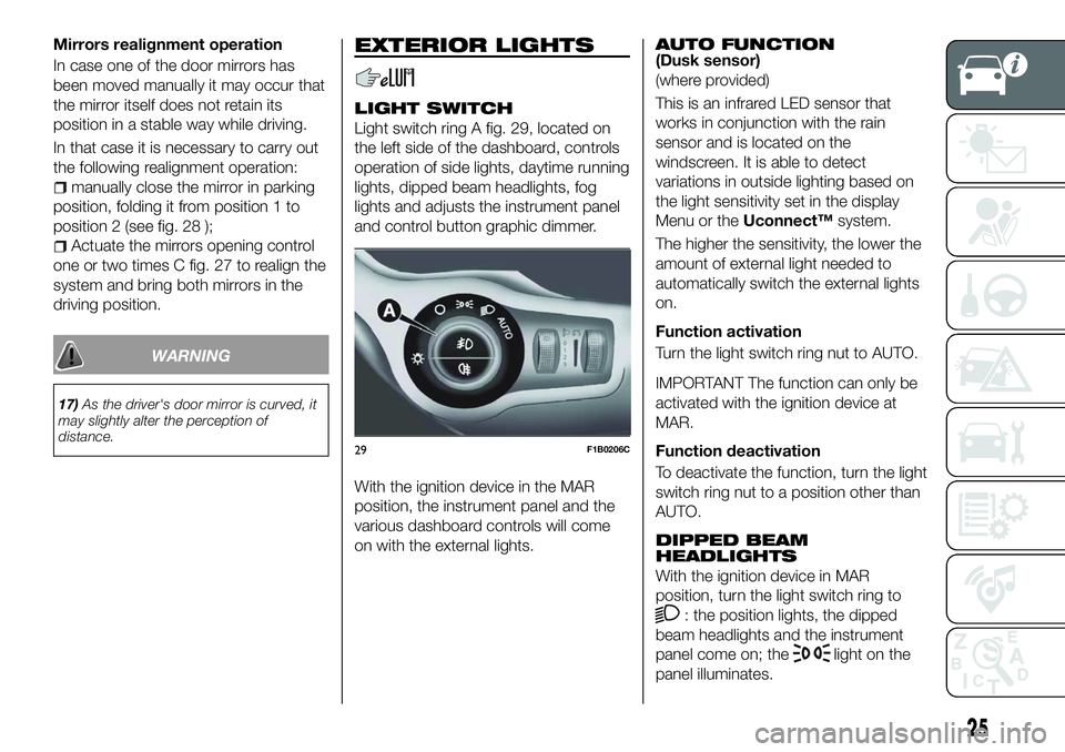
manually close the mirror in parking
position, folding it from position 1 to
position 2 (see fig. 28 );
Actuate the mirrors opening control
one or two times C fig. 27 to realign the
system and bring both mirrors in the
driving position.
WARNING
17) As the driver's door mirror is curved, it
may slightly alter the perception of
distance.
EXTERIOR LIGHTS
LIGHT SWITCH
Light switch ring A fig. 29, located on
the left side of the dashboard, controls
operation of side lights, daytime running
lights, dipped beam headlights, fog
lights and adjusts the instrument panel
and control button graphic dimmer.
With the ignition device in the MAR
position, the instrument panel and the
various dashboard controls will come
on with the external lights.
AUTO FUNCTION(Dusk sensor)
(where provided)
This is an infrared LED sensor that
works in conjunction with the rain
sensor and is located on the
windscreen. It is able to detect
variations in outside lighting based on
the light sensitivity set in the display
Menu or the Uconnect™ system.
The higher the sensitivity, the lower the
amount of external light needed to
automatically switch the external lights
on.
Function activation
Turn the light switch ring nut to AUTO.
IMPORTANT The function can only be
activated with the ignition device at
MAR.
Function deactivation
To deactivate the function, turn the light
switch ring nut to a position other than
AUTO.
DIPPED BEAM
HEADLIGHTS
With the ignition device in MAR
position, turn the light switch ring to
: the position lights, the dipped
beam headlights and the instrument
panel come on; the
light on the
panel illuminates.
29F1B0206C
25
Page 28 of 276
DAYTIME RUNNING
LIGHTS (DRL)
"Daytime Running Lights"
18) 19)
With the ignition device in the MAR
position and the light ring turned to the
Oposition, the daytime running lights
are automatically activated. The other
lights and interior lighting remain off.
The daytime running lights are
temporarily deactivated when the
direction indicators are activated. When
the direction indicators are deactivated,
the daylight running lights are
reactivated.
FOG LIGHTS(where provided)
The fog light switch is integrated with
the light switch.
With the ignition device in the MAR
position and the dipped beam
headlights on, press the
button to
switch on the fog lights.
When the fog lights are on, the position
and number plates lights are on while
the daytime running lights are off.
To switch them off, press the button
again or turn the light switch ring to O.
REAR FOG LIGHT(where provided)
The button which turns the rear fog light
on and off is integrated in the light
switch.
With the ignition device in the MAR
position and the dipped beam
headlights or fog lights on, press the
button to switch on the rear fog
light.
PARKING LIGHTS
These can be turned on by turning the
light switch ring to the
position.
The
warning light switches on in
the instrument panel.
IMPORTANT NOTE Do not select this
light switch position when the car is
moving, but only to indicate that the car
is parked when prescribed by the
regulations in force in the country where
you are driving (Highway Code).
To turn the lights off, turn the light
switch ring to the Oposition
HEADLIGHTS OFF DELAY
(Follow me home)
Activation
With multifunction display and
Uconnect™Radio: turn the ignition
device to STOP. Within 2 minutes, pull
the left stalk to headlight flashing mode:
the headlight off delay is activated for
30 seconds. The function can be activated for 7 times in sequence, i.e.
up to a total of 210 seconds.
With reconfigurable multifunction
display and/orUconnect™7'': the
headlight off delay can be set (from 0,
30, 60 to 90 seconds) in the Menu.
If the headlight off delay is set to
0 seconds, it is possible to turn on the
lights for a predefined time of
30 seconds using the main beam
headlights stalk within 2 minutes after
stopping the engine. It is possible to
turn on the lights 7 times, for a
maximum of 210 seconds.
If the value set on the Menu is different
from 0, the lights can be switched of for
the predetermined time by taking the
ring from position
(with the engine
running) to position O(with the engine
off).
The function can be activated
automatically on versions with dusk
sensor: turn the ring to the AUTO
position with the engine running. The
dipped beam headlights will be turned
on if the sensor detects a low level of
light. The headlights off delay is
activated automatically when the engine
is switched off with the headlights on
for the time selected in the Menu.
26
GETTING TO KNOW YOUR CAR
Page 29 of 276
Deactivation
If the function is activated by using the
left steering wheel stalk, the function
can be deactivated by holding the left
lever in "main beam flashing" mode for
longer than 2 seconds or by waiting for
the deactivation time shown on the
display.
The function cannot be deactivated if it
is activated using the light line. The
headlights will be switched off at the
end of the set time.
Turning the ignition device to the MAR
position will deactivate the function.
MAIN BEAM HEADLIGHTS
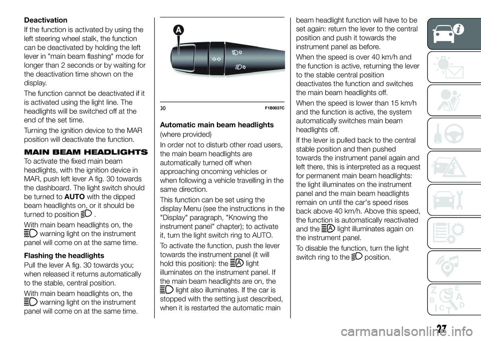
To activate the fixed main beam
headlights, with the ignition device in
MAR, push left lever A fig. 30 towards
the dashboard. The light switch should
be turned toAUTOwith the dipped
beam headlights on, or it should be
turned to position
.
With main beam headlights on, the
warning light on the instrument
panel will come on at the same time.
Flashing the headlights
Pull the lever A fig. 30 towards you;
when released it returns automatically
to the stable, central position.
With main beam headlights on, the
warning light on the instrument
panel will come on at the same time. Automatic main beam headlights
(where provided)
In order not to disturb other road users,
the main beam headlights are
automatically turned off when
approaching oncoming vehicles or
when following a vehicle travelling in the
same direction.
This function can be set using the
display Menu (see the instructions in the
"Display" paragraph, "Knowing the
instrument panel" chapter); to activate
it, turn the light switch ring to AUTO.
To activate the function, push the lever
towards the instrument panel (it will
hold this position): the
light
illuminates on the instrument panel. If
the main beam headlights are on, the
light also illuminates. If the car is
stopped with the setting just described,
when it is restarted the automatic main beam headlight function will have to be
set again: return the lever to the central
position and push it towards the
instrument panel as before.
When the speed is over 40 km/h and
the function is active, returning the lever
to the stable central position
deactivates the function and switches
the main beam headlights off.
When the speed is lower than 15 km/h
and the function is active, the system
automatically switches main beam
headlights off.
If the lever is pulled back to the central
stable position and then pushed
towards the instrument panel again and
left there, this is interpreted as a request
for permanent main beam headlights:
the light illuminates on the instrument
panel and the main beam headlights
remain on until the car's speed rises
back above 40 km/h. Above this speed,
the function is automatically reactivated
and the
light illuminates again on
the instrument panel.
To disable the function, turn the light
switch ring to the
position.
30F1B0037C
27
Page 30 of 276
DIRECTION INDICATORS
Bring left stalk A fig. 30 to the (stable)
position:
upwards: activates the right direction
indicator;
downwards: activates the left direction
indicator.
The
orwarning light respectively
will flash on the instrument panel.
The direction indicators switch off
automatically when the steering wheel
is straightened or when the daytime
running lights (DRL)/parking lights are
activated.
"Lane Change" function
If you wish to signal a lane change while
running, place the left stalk in the
unstable position for less than half a
second.
The direction indicator on the side
selected will flash five times and then
switch off automatically.
HEADLIGHT ALIGNMENT
ADJUSTMENT
Headlight alignment corrector
The headlight alignment corrector
operates with ignition device at MAR
and dipped headlights on.
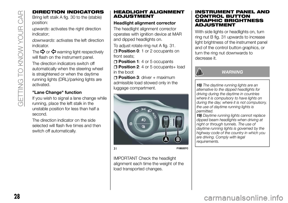
To adjust rotate ring nut A fig. 31.
Position 0: 1 or 2 occupants on
front seats;
Position 1: 4 or 5 occupants
Position 2: 4 or 5 occupants+ load
in the boot
Position 3: driver + maximum
admissible load stowed only in the
luggage compartment.
IMPORTANT Check the headlight
alignment each time the weight of the
load transported changes. INSTRUMENT PANEL AND
CONTROL BUTTON
GRAPHIC BRIGHTNESS
ADJUSTMENT
With side lights or headlights on, turn
ring nut B fig. 31 upwards to increase
light brightness of the instrument panel
and of the control button graphics, or
turn the ring nut downwards to
decrease it.
WARNING
18)
The daytime running lights are an
alternative to the dipped headlights for
driving during the daytime in countries
where it is compulsory to have lights on
during the day; where it is not compulsory,
the use of daytime running lights is
permitted.
19) Daytime running lights cannot replace
dipped beam headlights when driving at
night or through tunnels. The use of
daytime running lights is governed by the
highway code of the country in which you
are driving. Comply with legal
requirements.
31F1B0207C
28
GETTING TO KNOW YOUR CAR