brake light FIAT 500X 2018 Owner handbook (in English)
[x] Cancel search | Manufacturer: FIAT, Model Year: 2018, Model line: 500X, Model: FIAT 500X 2018Pages: 276, PDF Size: 7.08 MB
Page 121 of 276
WARNING
113)Depress the clutch pedal fully to
change gear correctly. It is therefore
essential that there is nothing under the
pedals: make sure the mats are lying flat
and do not get in the way of the pedals.
IMPORTANT
47) Do not drive with your hand resting on
the gear lever as the force exerted, even if
slight, could lead over time to premature
wear of the gearbox internal components.
AUTOMATIC
TRANSMISSION
GEAR LEVER
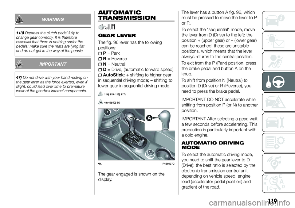
The fig. 96 lever has the following
positions:
P = Park
R = Reverse
N = Neutral
D= Drive, (automatic forward speed)
AutoStick: + shifting to higher gear
in sequential driving mode; – shifting to
lower gear in sequential driving mode.
114) 115) 116) 117)
48) 49) 50) 51)
The gear engaged is shown on the
display. The lever has a button A fig. 96, which
must be pressed to move the lever to P
or R.
To select the "sequential" mode, move
the lever from D (Drive) to the left: the
position + (upper gear) or – (lower gear)
can be reached; these are unstable
positions, which means that the lever
always returns to the central position.
To exit from the P (Park) position, press
the brake pedal and button A on the
knob.
To shift from position N (Neutral) to
position D (Drive) or R (Reverse), you
need to press the brake pedal.
IMPORTANT DO NOT accelerate while
shifting from position P (or N) to another
position.
IMPORTANT After selecting a gear, wait
a few seconds before accelerating. This
precaution is particularly important with
a cold engine.
AUTOMATIC DRIVING
MODE
To select the automatic driving mode,
you need to shift the gear lever to D
(Drive): the best ratio is selected by the
electronic transmission control unit
depending on vehicle speed, engine
load (accelerator pedal position) and
gradient of the road.
96F1B0137C
119
Page 123 of 276
STARTING THE ENGINE
Starting the engine is allowed only
when the gear lever is in position P or
N. Therefore, when the engine is
started, the system will be at position N
or P (the latter means neutral, but with
the vehicle's wheels are locked
mechanically).
MOVING THE CAR
To move the car, from P press the brake
pedal and, using the button on the gear
lever, move the lever to the desired
position (D, R or "Sequential mode").
The display will show the gear engaged.
When the brake pedal is released, the
car starts moving forwards or
backwards, as soon as the manoeuvre
is activated ("creeping" effect). The
accelerator should not be pressed in
this case.
IMPORTANT The inconsistency
between the speed actually engaged
(shown on the display) and the position
of the gear lever is indicated by the
letter corresponding to the position of
the lever flashing on the trim (also
accompanied by an acoustic signal).
This condition should not be interpreted
as an operational fault, but simply as a
request by the system to repeat the
manoeuvre.
IMPORTANT With the electric parking
brake released and brake pedal
released, engine at idling speed and
gear lever in position D, R or sequential,
pay the utmost care because the car
can move even without the operation of
the accelerator pedal. This condition
can be used with the car on a level
surface during tight parking
manoeuvres using the brake pedal only.
GEAR ENGAGEMENT
INHIBITION
This system prevents you from moving
the gear lever from position P (Park) or
N (Neutral) if the brake pedal has not
been previously depressed.
When the ignition device is in MAR
(engine on or off):
to shift the gear to a position
different from P (Park) or from N to R,
you need to press the brake pedal and
the button A fig. 96 on the knob of the
gear lever;
to shift the lever from position N to
position D, press the brake pedal.
In case of a failure or when the vehicle's
battery is flat, the lever remains locked
in position P. To manually unlock the
lever, see paragraph "Automatic
transmission - lever unlocking" in the "In
an emergency" chapter.
VEHICLE SHUTDOWN
Versions equipped with the Keyless
Go system: this function requires the
gear lever to be positioned at P (Park);
then bring the ignition device to STOP.
Versions equipped with key without
remote control: this function requires
the gear lever to be positioned at P
(Park) before extracting the key from the
ignition device.
If the vehicle battery is flat and the
ignition key is engaged, the latter is
locked in position. To remove the key
manually see paragraph "Automatic
transmission - key removal" in the
chapter "In an emergency".
"RECOVERY" OPERATION(where provided)
Transmission operation is constantly
monitored to detect any fault. If a
condition that might damage the
transmission is detected, the "recovery"
function is activated.
In this condition, the transmission stays
in 4
thgear, regardless of the selected
gear.
Positions P (Parking), R (Reverse) and N
(Neutral) still work. Icon
might light
up in the display.
In the case of "recovery" operation
immediately contact the nearest Fiat
Dealership.
121
Page 128 of 276
Thewarning light on the instrument
panel switches on to signal that the
engine was stopped.
Engine restarting mode
Versions with manual gearbox
To restart the engine, press the clutch
pedal. If the vehicle does not start when
the clutch is pressed, place the gear
lever in neutral and repeat the
procedure. If the problem persists,
contact a Fiat Dealership.
Versions with automatic
transmission
To restart the engine, release the brake
pedal.
With brake pressed, if the gear lever is
in automatic mode - D (Drive) - the
engine can be restarted by moving the
lever to R (Reverse) or N (Neutral) or
"AutoStick".
With brake pressed, if the gear lever is
in "AutoStick" mode, the engine can be
restarted moving the lever to "+" or "–",
or R (Reverse) or N (Neutral).
When the engine has been stopped
automatically, keeping the brake pedal
pressed, the brake can be released
keeping the engine off by quickly
shifting the gear lever to P (Park).
To restart the engine, just move the
lever out of position P.SYSTEM MANUAL
ACTIVATION /
DEACTIVATION
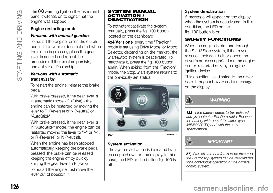
To activate/deactivate the system
manually, press the fig. 100 button
located on the dashboard.
4x4 Versions: every time "Traction"
mode is set using Drive Mode (or Mood
Selector, depending on the market), the
Start&Stop system is deactivated. To
reactivate it, press the fig. 100 button
again. When exiting from the "Traction"
mode, the Stop/Start system returns to
the previously set status.
System activation
The system activation is indicated by a
message shown on the display. In this
case, the LED on the button fig. 100 is
off. System deactivation
A message will appear on the display
when the system is deactivated. In this
condition, the LED on the
fig. 100 button is on.
SAFETY FUNCTIONS
When the engine is stopped through
the Start&Stop system, if the driver
releases their seat belt or opens the
driver's or passenger's door, the engine
can be restarted only by using the
ignition device.
This condition is indicated to the driver
both through a buzzer and a message
on the display.
WARNING
122)
If the battery needs to be replaced,
always contact a Fiat Dealership. Replace
the battery with one of the same type
(HEAVY DUTY) and with the same
specifications.
IMPORTANT
57) If the climate comfort is to be favoured,
the Start&Stop system can be deactivated,
for a continuous operation of the climate
control system.
100F1B0631C
126
STARTING AND DRIVING
Page 130 of 276
The device cannot be engaged in 1st
or reverse gear: it is advisable to
engage it in 3rdgear or higher.
IMPORTANT It is dangerous to leave
the device on when it is not used. There
is a risk of inadvertently activating it and
losing control of the vehicle due to
unexpected excessive speed.
SETTING THE DESIRED
SPEED
Proceed as follows:
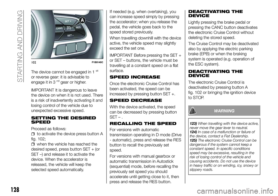
to activate the device press button A
fig. 102;
when the vehicle has reached the
desired speed, press button SET + (or
SET –) and release it to activate the
device. When the accelerator is
released, the vehicle will keep the
selected speed automatically. If needed (e.g. when overtaking), you
can increase speed simply by pressing
the accelerator; when you release the
pedal, the vehicle goes back to the
speed stored previously.
When travelling downhill with the device
active, the vehicle speed may slightly
exceed the set one.
IMPORTANT Before pressing the SET +
or SET – buttons, the vehicle must be
travelling at a constant speed on a flat
surface.
SPEED INCREASE
Once the electronic Cruise Control has
been activated, the speed can be
increased by pressing button SET +.
SPEED DECREASE
With the device activated, the speed
can be decreased by pressing button
SET–.
RECALLING THE SPEED
For versions with automatic
transmission operating in D mode (Drive
- automatic), press and release the RES
button to recall the previously set
speed.
For versions with manual gearbox or
automatic transmission in Autostick
(sequential) mode, before recalling the
previously set speed you should
accelerate until getting close to it, then
press and release the RES button.
DEACTIVATING THE
DEVICE
Lightly pressing the brake pedal or
pressing the CANC button deactivates
the electronic Cruise Control without
deleting the stored speed.
The Cruise Control may be deactivated
also by applying the electric parking
brake (EPB) or when the braking
system is operated (e.g. operation of
the ESC system).
DEACTIVATING THE
DEVICE
The electronic Cruise Control is
deactivated by pressing button A
fig. 102 or bringing the ignition device
to STOP.
WARNING
123)
When travelling with the device active,
never move the gear lever to neutral.
124) In case of a malfunction or failure of
the device, contact a Fiat Dealership.
125) The electronic Cruise Control can be
dangerous if the system cannot keep a
constant speed. In specific conditions
speed may be excessive, resulting in the
risk of losing control of the vehicle and
causing accidents. Do not use the device
in heavy traffic or on winding, icy, snowy or
slippery roads.
102F1B0140C
128
STARTING AND DRIVING
Page 140 of 276
If the vehicle continues going beyond
the line of the lane without any
intervention from the driver, the
warning light (or the icon on the
display) will be displayed on the
instrument panel to urge the driver to
bring the vehicle back into the limits of
the lane.
IMPORTANT The system monitors the
presence of the driver's hands on the
steering wheel. If they are not detected,
the system emits an acoustic signal and
deactivates until it is reactivated by
pressing the dedicated button (see
description below).
When one limit of the lane is detected
and the vehicle crosses it (direction
indicator off), warning light
(or the
icon on the display) will be displayed on
the instrument panel to urge the driver
to bring the vehicle back into the lane.
In this case, the tactile warning
(vibration on the steering wheel) is not
provided.
SYSTEM ACT_IVATION/
DEACTIVATION
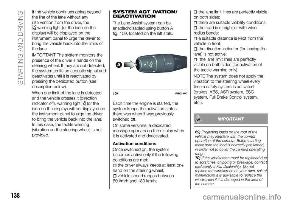
The Lane Assist system can be
enabled/disabled using button A
fig. 109, located on the left stalk.
Each time the engine is started, the
system keeps the activation status
there was when it was previously
switched off.
On some versions, a dedicated
message appears on the display when
it is activated and deactivated.
Activation conditions
Once switched on, the system
becomes active only if the following
conditions are met:
the driver always keeps at least one
hand on the steering wheel;
vehicle speed ranges between
60 km/h and 180 km/h;
the lane limit lines are perfectly visible
on both sides;
there are suitable visibility conditions;
the road is straight or with wide
radius bends;
a suitable distance is kept from the
vehicle in front;
the direction indicator (for leaving the
lane) is not active;
the lane limit lines are perfectly
visible on both sides (for activation of
the tactile warning only).
NOTE The system does not apply the
vibration to the steering wheel every
time a safety system is activated
(brakes, ABS, ASR system, ESC
system, Full Brake Control system,
etc.).
IMPORTANT
69) Projecting loads on the roof of the
vehicle may interfere with the correct
operation of the camera. Before starting
make sure the load is correctly positioned,
in order not to cover the camera operating
range.
70) If the windscreen must be replaced due
to scratches, chipping or breakage, contact
exclusively a Fiat Dealership. Do not
replace the windscreen on your own, risk of
malfunction! It is advisable to replace the
windscreen if it is damaged in the area of
the camera.
109F1B0334C
138
STARTING AND DRIVING
Page 142 of 276
WARNING
133)Parking and other potentially
dangerous manoeuvres are, however,
always the driver’s responsibility. While
carrying out these manoeuvres, always
make sure that no people (especially
children) or animals are in the area
concerned. The camera is an aid for the
driver, but the driver must never allow
his/her attention to lapse during potentially
dangerous manoeuvres, even those
executed at low speeds. Always keep a
slow speed, so as to promptly brake in the
case of obstacles.
IMPORTANT
75) It is vital, for correct operation, that the
camera is always kept clean and free from
any mud, dirt, snow or ice. Be careful not
to scratch or damage the camera while
cleaning it. Avoid using dry, rough or hard
cloths. The camera must be washed using
clean water, with the addition of car
shampoo if necessary. In washing stations
which use steam or high-pressure jets,
clean the camera quickly, keeping the
nozzle more than 10 cm away from the
sensors. Also, do not apply stickers to the
camera.
TOWING TRAILERS
IMPORTANT
134) 135)
For towing caravans or trailers the
vehicle must be fitted with an approved
tow hook and an adequate electrical
system. Should aftermarket installation
be requested, this must be carried out
by specialists.
Install any specific and/or additional
door mirrors as specified by the
Highway Code.
Remember that when towing a trailer,
steep hills are harder to climb, braking
distances increase and overtaking takes
longer depending on the overall weight
of the trailer. Engage a low gear when
driving downhill, rather than constantly
using the brake. The weight the trailer
exerts on the vehicle tow hook reduces
the vehicle's loading capacity by the
same amount. To make sure that the
maximum towable weight is not
exceeded (given in the vehicle
registration document) account should
be taken of the fully laden trailer,
including accessories and luggage. Do not exceed the speed limits specific
to each country you are driving in, in the
case of vehicles towing trailers. In any
case, the top speed must not exceed
100 km/h.
Any electric brake must be powered
directly by the battery through a cable
with a cross-section of no less than
2.5 mm
2. In addition to the electrical
branches, the vehicle electrical system
can only be connected to the supply
cable for an electric brake and to the
cable for an internal light for the trailer,
not exceeding 15 W. For connections,
use the preset control unit with a
battery cable with section not less than
2.5 mm
2. The use of auxiliary loads
other than external lights (e.g. electric
brake) must take place with engine
running.
140
STARTING AND DRIVING
Page 152 of 276
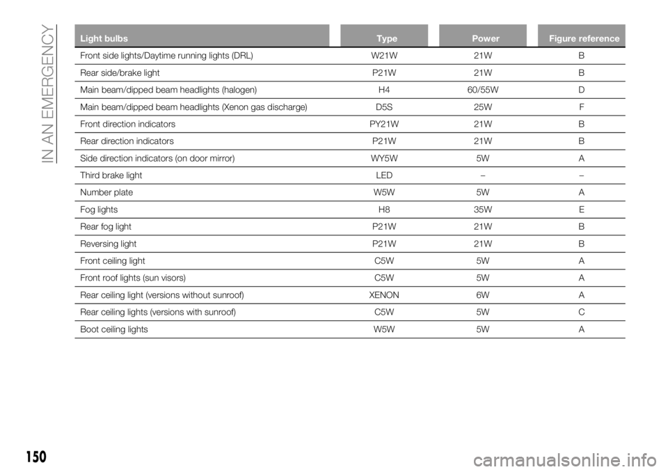
Light bulbsTypePowerFigure reference
Front side lights/Daytime running lights (DRL) W21W21W B
Rear
side/brake light P21W21W B
Main beam/dipped beam headlights (halogen) H460/55W D
Main beam/dipped beam headlights (Xenon gas discharge) D5S25W F
Front direction indicators PY21W21W B
Rear direction indicators P21W21W B
Side direction indicators (on door mirror) WY5W5WA
Third brake light LED––
Number plate W5W5WA
Fog lights H835W E
Rear fog light P21W21W B
Reversing light P21W21W B
Front ceiling light C5W5W A
Front roof lights (sun visors) C5W5W A
Rear ceiling light (versions without sunroof) XENON6WA
Rear ceiling lights (versions with sunroof) C5W5W C
Boot ceiling lights W5W5WA
150
IN AN EMERGENCY
Page 155 of 276
release the tabs shown by the arrows
and extract the bulb holder assembly D
fig. 124;
identify the bulb to be replaced
(1 Positions/Stop - 2 Direction indicator
- 3 Rear fog light (where provided) or
Reverse);
all bulbs are "bayonet-fitted"; to
replace them, press slightly and turn at
the same time: anticlockwise to extract;
clockwise to insert;
reposition the bulb holder assembly
D correctly in the headlight body;
proceed until you hear the tabs click;
fasten the two screws C fig. 123 and
reconnect the central connector B;
refit the lens by screwing the two
screws A completely;
close the tailgate.
3
rdbrake lights
The 3rdbrake lights are LED-based. To
replace them, contact a Fiat Dealership.
Number plate lights
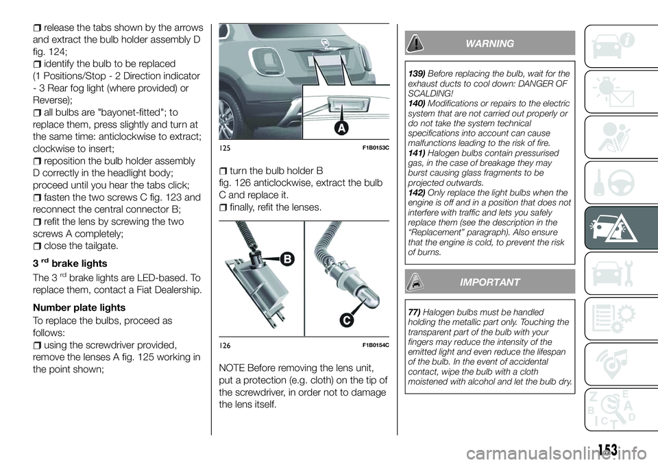
To replace the bulbs, proceed as
follows:
using the screwdriver provided,
remove the lenses A fig. 125 working in
the point shown;
turn the bulb holder B
fig. 126 anticlockwise, extract the bulb
C and replace it.
finally, refit the lenses.
NOTE Before removing the lens unit,
put a protection (e.g. cloth) on the tip of
the screwdriver, in order not to damage
the lens itself.
WARNING
139) Before replacing the bulb, wait for the
exhaust ducts to cool down: DANGER OF
SCALDING!
140) Modifications or repairs to the electric
system that are not carried out properly or
do not take the system technical
specifications into account can cause
malfunctions leading to the risk of fire.
141) Halogen bulbs contain pressurised
gas, in the case of breakage they may
burst causing glass fragments to be
projected outwards.
142) Only replace the light bulbs when the
engine is off and in a position that does not
interfere with traffic and lets you safely
replace them (see the description in the
“Replacement” paragraph). Also ensure
that the engine is cold, to prevent the risk
of burns.
IMPORTANT
77) Halogen bulbs must be handled
holding the metallic part only. Touching the
transparent part of the bulb with your
fingers may reduce the intensity of the
emitted light and even reduce the lifespan
of the bulb. In the event of accidental
contact, wipe the bulb with a cloth
moistened with alcohol and let the bulb dry.
125F1B0153C
126F1B0154C
153
Page 161 of 276
WARNING
143)If the replaced fuse blows again,
contact a Fiat Dealership.
144) Never replace a fuse with another
with a higher amp rating; DANGER OF
FIRE
145) If a fuse NOT indicated in this or the
previous page is used, contact a Fiat
Dealership.
146) Before replacing a fuse, make sure
that the ignition device is at STOP, that the
key, if mechanical, has been removed and
that all devices are switched off and/or
disconnected.
IMPORTANT
78) Never replace a fuse with metal wires
or anything else.
79) If it is necessary to wash the engine
compartment, take care not to directly hit
the fuse box and the window wiper motor
with the water jet.
CHANGING A WHEEL
JACK
154) 155)
Please note that:
the jack weight is 2.8 kg;
the jack requires no adjustment;
the jack cannot be repaired and in
the event of a fault it must be replaced
by another genuine one;
no tool other than its cranking device
may be fitted on the jack.
Maintenance
prevent any dirt from depositing on
the "worm screw";
keep the "worm screw" lubricated;
never modify the jack.
Conditions for non-use
temperatures below −40°C;
on sandy or muddy ground;
on uneven ground;
on steep roads;
in extreme weather conditions:
thunderstorms, typhoons, hurricanes,
blizzards, storms, etc...
in direct contact with the engine or
for repairs under the car;
on boats.
CHANGING PROCEDURE
147) 148) 149) 150) 151) 152) 153)
Proceed as follows:
stop the car in a position that is not
dangerous for oncoming traffic where
you can change the wheel safely. The
ground must be flat and sufficiently
compact;
stop the engine, engage the hazard
warning lights and the electric parking
brake;
engage first gear or reverse or, for
versions with automatic transmission,
move the lever to position P (Park);
wear the reflective safety jacket
(compulsory by law) before getting out
of the car;
open the luggage compartment and
set the adjustable load platform in the
diagonal position (see "Luggage
Compartment" section of the "Getting
to know your car" chapter);
take out the tool bag supplied,
anchored to the boot mat by special
fasteners. The bag contains fig. 133:
jack A; screwdriver B; adaptor C for
refuelling in the event of an emergency;
pin D for centring the wheel (where
provided, to be used in the spare wheel
fitting procedure); special anti-theft nut
E (where provided, to be used in the
wheel stud bolt fitting/removal
procedure); chock F for blocking the
159
Page 165 of 276
153)Never tamper with the inflation valve.
Never introduce tools of any kind between
the rim and the tyre. Check tyre and
space-saver wheel pressures regularly,
complying with the values given in the
"Technical specifications" chapter.
154) The jack is a tool developed and
designed only for changing a wheel, if a
tyre gets punctured or damaged, on the
vehicle with which it is supplied or on other
vehicles of the same model. Any other use,
e.g. to jack up other vehicle models or
different things, is strictly prohibited. Never
use it to carry out maintenance or repairs
under the vehicle or to change
summer/winter wheels and vice versa: we
advise you to contact a Fiat Dealership.
Never go under the raised vehicle: use it
only in the positions indicated. Do not use
the jack for loads higher than the one
shown on its label. Never start the engine
with car raised. If the car is raised more
than necessary, everything can become
more unstable, with the risk of the car
dropping violently. Thus, lift the car only as
needed in order to access the space-saver
spare wheel.
155) When turning the jack handle make
sure that it can turn freely without scraping
your hand against the ground. The moving
components of the jack ("worm screw" and
joints) can also cause injuries: do not touch
them. If you come into contact with
lubricating grease, clean yourself
thoroughly.FIX&GO AUTOMATIC
KIT
(where provided)
156) 157)
80)
DESCRIPTION
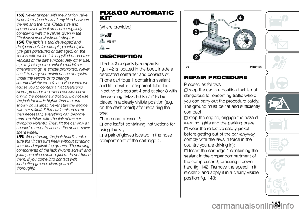
The Fix&Go quick tyre repair kit
fig. 142 is located in the boot, inside a
dedicated container and consists of:
one cartridge 1 containing sealant
and fitted with: transparent tube for
injecting the sealant 4 and sticker 3 with
the wording “Max. 80 km/h” to be
placed in a clearly visible position (e.g.
on the dashboard) after repairing the
tyre;
one compressor 2;
one leaflet containing instructions for
using the kit;
a pair of gloves located in the hose
compartment of the cartridge 4.
REPAIR PROCEDURE
Proceed as follows:
stop the car in a position that is not
dangerous for oncoming traffic where
you can carry out the procedure safely.
The ground must be flat and sufficiently
compact;
stop the engine, engage the hazard
warning lights and the parking brake;
wear the reflective safety jacket
before getting out of the car (anyway
comply with the laws in force in the
country you are driving in);
Insert the cartridge 1 containing the
sealant in the proper compartment of
the compressor 2, pressing it down
hard fig. 142. Remove the speed limit
sticker 3 and apply it in a clearly visible
position fig. 143;
142P2000158
163